2. 中国石油勘探开发研究院, 北京 海淀 100083;
3. 中国石油玉门油田分公司老君庙作业区, 甘肃 玉门 735200
2. Research Institute of Petroleum Exploration & Development, CNPC, Haidian, Beijing 100083, China;
3. Laojunmiao Operation Area of Yumen Oilfield, PetroChina, Yumen, Gansu 735200, China
水平井蒸汽吞吐是目前中国稠油油藏高效开发最主要的方法之一,而准确预测蒸汽吞吐水平段加热范围对稠油油藏水平井的开发至关重要[1]。
目前计算水平井蒸汽吞吐加热面积最常用的加热模式主要有:马克斯-兰根海姆(Marx-Langenheim)法、威尔曼(Willman)法等。但由于稠油在蒸汽吞吐开采过程中,具有强非稳定性特征,即压力和流温同时发生变化,渗流机理非常复杂[2-4]。
中国有关水平井蒸汽吞吐加热范围预测方面的研究不多,主要有倪学锋、刘春泽根据水平井变质量流和传热学原理,建立了蒸汽沿水平段的压力、温度和干度分布计算模型和水平井蒸汽吞吐加热半径及焖井后温度压力计算模型;郑舰推导了加热区半径计算公式和初期产量预测公式,弥补了传统模型的不足;窦宏恩等通过Buck-Leverret方程推导出热水带的加热半径并应用到稠油油藏的井网设计中[5-10]。以上学者对水平井蒸汽吞吐水平段加热范围预测方面的研究对水平井产能评价和动态预测都起到了重要的基础作用,但由于推导公式中含有双重积分,计算复杂,需要消耗大量的时间。因此有必要研究一种简单且不失准确性的方法来预测水平井蒸汽吞吐加热范围。
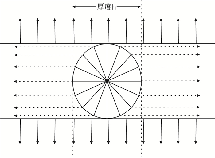
本文在Marx-Langenheim直井加热范围公式推导基础上,将原有模型简化,推导出一个形式简单、应用方便的解析公式,图 1为蒸汽加热模型示意图。
 |
| 图1 蒸汽加热示意图 Fig. 1 Schematic diagram of steam heating |
基本条件假设:
(1) 加热模式将热传导分成两个阶段:第1阶段:当热量传至顶底盖层之前,即近井区域的径向热传导,其最大加热半径设为油层厚度的一半,即h/2;第2阶段:该阶段的传热过程可分为两部分:一是向顶底盖层的热损失;二是向油层的线性传热。
(2) 水平段长度不宜过长,因此不考虑沿程引起的温度变化和摩擦损失。
(3) 沿水平井井筒注汽剖面均匀。
(4) 油层温度在加热区内基本相等,未加热区温度为原始油层温度(此假设忽略了蒸汽前缘的热水汇集区域温度逐渐降低的现象)。
(5) 油层相对较薄,不考虑蒸汽超覆现象。
(6) 水平井位于油层中部位置。
2 数学模型的推导过程 2.1 近井径向加热区域加热半径与注汽时间的关系模型注汽初期,热传导未达到油层顶底边界,因此,假设蒸汽热量只用来加热油层,而没有热量损失,根据Marx-Langenhein模型,遵守能量守恒定律,即:井底注入能量=顶底盖层损失的能量-油层能量的增加
| $ M_{\rm{R}} {\rm{d}}AL\left( {T_{\rm{S}} - T_{\rm{i}} } \right) = i_{\rm{S}} h_{\rm{m}} {\rm{d}}t $ | (1) |
| $ {\rm{d}}A = 2π r{\rm{d}}r $ | (2) |
将式(2)代入式(1)积分,可得
| $ \int_0^{t_{\rm{r}} } {\mathop i\nolimits_{\rm{S}} } \mathop h\nolimits_{\rm{m}} {\rm{d}}t = \int_{R_{\rm{w}} }^{R_1 } {\mathop M\nolimits_{\rm{R}} } L\left( {\mathop T\nolimits_{\rm{S}} - \mathop T\nolimits_{\rm{i}} } \right)2π r{\rm{d}}r $ | (3) |
| $ \mathop t\nolimits_{\rm{r}} = \dfrac{{π \mathop M\nolimits_{\rm{R}} L\left( {\mathop T\nolimits_{\rm{S}} - \mathop T\nolimits_{\rm{i}} } \right)\left( {\mathop R\nolimits_1^2 - \mathop R\nolimits_{\rm{w}}^2 } \right)}}{{\mathop i\nolimits_{\rm{S}} \mathop h\nolimits_{\rm{m}} }} $ | (4) |
式中:
MR-油层热容量,kJ/(m3·℃);
dA-加热截面积变化量,m2;
A-加热区蒸汽面积,m2;
L-水平段长度,m;
TS-饱和蒸汽温度,℃;
Ti-原始油层温度,℃;
iS-蒸汽注入速率,kg/h;
hm-饱和蒸汽的焓,kJ/kg;
t-注汽时间,h;
r-水平段加热半径,m;
Rw-水平井筒半径,m;
R1-第一时间阶段加热半径,m;
tr-第1阶段注汽时间,h。
随着注汽时间增加,加热半径不断增大,当热量传至油层顶底隔层时,加热半径即为油层厚度的一半,此时所对应的时间即为第1阶段结束时间。
2.2 第2阶段加热范围计算推导根据第1阶段热传导过程,将第2阶段热传导分成3部分:(1) 向油层的线性传导;(2) 近井区域向顶底层的热损失(其恒定面积为hL);(3) 远井区域向顶底隔层的热损失,热传导面积逐渐增加。
根据能量守恒原理,可得
| $ \mathop i\nolimits_{\rm{S}} \mathop h\nolimits_{\rm{m}} = \dfrac{{2\mathop \lambda \nolimits_{\rm{S}} \left( {\mathop T\nolimits_{\rm{S}} - \mathop T\nolimits_{\rm{i}} } \right)}}{{\sqrt {π \mathop \alpha \nolimits_{\rm{S}} t} }}h \times L + 2\int_0^A {\dfrac{{\mathop \lambda \nolimits_{\rm{S}} \left( {\mathop T\nolimits_{\rm{S}} - \mathop T\nolimits_{\rm{i}} } \right)}}{{\sqrt {π \mathop \alpha \nolimits_{\rm{S}} t} }}{\rm{d}}A} + \mathop M\nolimits_{\rm{R}} \dfrac{{{\rm{d}}A}}{{{\rm{d}}t}}h\left( {\mathop T\nolimits_{\rm{S}} - \mathop T\nolimits_{\rm{i}} } \right) $ | (5) |
对式(5)进行拉普拉斯(Laplace)变换,可得
| $ L\left( {\mathop i\nolimits_{\rm{S}} \mathop h\nolimits_{\rm{m}} } \right) = \dfrac{{\mathop i\nolimits_{\rm{S}} \mathop h\nolimits_{\rm{m}} }}{S} $ | (6) |
| $ L\left[{\dfrac{{2\mathop \lambda \nolimits_{\rm{S}} \left( {\mathop T\nolimits_{\rm{S}}-\mathop T\nolimits_{\rm{i}} } \right)}}{{\sqrt {π \mathop \alpha \nolimits_{\rm{S}} t} }}h \times L} \right] = \dfrac{{2\mathop \lambda \nolimits_{\rm{S}} \left( {\mathop T\nolimits_{\rm{S}} - \mathop T\nolimits_{\rm{i}} } \right)hL}}{{\sqrt {\mathop \alpha \nolimits_{\rm{S}} } \sqrt S }} $ | (7) |
| $ L\left[{2\int_0^A {\dfrac{{\lambda_{\rm{S}}\left({T_{\rm{S}}\!-\!T_{\rm{i}}}\right)}}{{\sqrt {π \alpha_{\rm{S}}t}}}}{\rm{d}}A}\right]\!=\!\dfrac{{2\lambda_{\rm{S}}\left({T_{\rm{S}}\!-\!T_{\rm{i}}} \right)}}{{\sqrt {π \alpha_{\rm{S}}} }}S\sqrt {\dfrac{π}{S}}L\left\{A \right\} $ | (8) |
| $ L\left[{\mathop M\nolimits_{\rm{R}} \dfrac{{{\rm{d}}A}}{{{\rm{d}}t}}h\left( {\mathop T\nolimits_{\rm{S}}-\mathop T\nolimits_{\rm{i}} } \right)} \right] = \mathop M\nolimits_{\rm{R}} h\left( {\mathop T\nolimits_{\rm{S}} - \mathop T\nolimits_{\rm{i}} } \right)SL\{ A\} $ | (9) |
式中:
λS-顶底层岩石导热系数,kJ/(h·m·℃);
αS-顶底层的热扩散系数,m2/h;
h-油层厚度,m;
S-复变量。
变换后的方程为
| $ \dfrac{{\mathop i\nolimits_{\rm{S}} \mathop h\nolimits_{\rm{m}} }}{S} = \dfrac{{2\mathop \lambda \nolimits_{\rm{S}} \left( {\mathop T\nolimits_{\rm{S}} - \mathop T\nolimits_{\rm{i}} } \right)hL}}{{\sqrt {\mathop \alpha \nolimits_{\rm{S}} } \sqrt S }} + \dfrac{{2\mathop \lambda \nolimits_{\rm{S}} \left( {\mathop T\nolimits_{\rm{S}} - \mathop T\nolimits_{\rm{i}} } \right)}}{{\sqrt {\mathop {π \alpha }\nolimits_{\rm{S}} } }}SL\{ A\} \sqrt {\dfrac{π }{S}} + \\ \mathop M\nolimits_{\rm{R}} h\left( {\mathop T\nolimits_{\rm{S}} - \mathop T\nolimits_{\rm{i}} } \right)SL\{ A\} $ | (10) |
| $ L\left\{A\right\}\!=\!\dfrac{{i_{\rm{S}}h_{\rm{m}}\!-\!2\lambda_{\rm{S}}\left({T_{\rm{S}}\!-\!T_{\rm{i}} } \right)hL\sqrt S/\sqrt {\alpha_{\rm{S}}}}}{{S^{\frac{3}{2}}\left[{M_{\rm{R}} h\left( {T_{\rm{S}}\!-\!T_{\rm{i}}}\right)\sqrt S\!+\!2\lambda_{\rm{S}}\left({T_{\rm{S}}\!-\!T_{\rm{i}}}\right)/\sqrt{\alpha_{\rm{S}}}}\right]}} $ | (11) |
对式(11)进行拉普拉斯(Laplace)逆变换,得到第2阶段加热面积即
| $ A\left( t \right) = \dfrac{{\mathop i\nolimits_{\rm{S}} \mathop h\nolimits_{\rm{m}} }}{{\mathop \lambda \nolimits_{\rm{S}} \left( {\mathop T\nolimits_{\rm{S}} - \mathop T\nolimits_{\rm{i}} } \right)}}\sqrt {\dfrac{{\mathop \alpha \nolimits_{\rm{S}} t}}{π }} + \left[{\dfrac{{\mathop i\nolimits_{\rm{S}} \mathop h\nolimits_{\rm{m}} \mathop M\nolimits_{\rm{R}} h\mathop {π \alpha }\nolimits_{\rm{S}} }}{{4\mathop \lambda \nolimits_{\rm{S}}^2 \left( {\mathop T\nolimits_{\rm{S}}-\mathop T\nolimits_{\rm{i}} } \right)}} + hL} \right] \\ \left[{\mathop {\rm{e}}\nolimits^{\dfrac{{4\mathop \lambda \nolimits_{\rm{S}}^2 }}{{\mathop \alpha \nolimits_{\rm{S}} \mathop M\nolimits_{\rm{R}}^2 \mathop h\nolimits^2 }}t} {\rm{erfc}}\left( {\dfrac{{2\mathop \lambda \nolimits_{\rm{S}} }}{{\sqrt {\mathop \alpha \nolimits_{\rm{S}} } \mathop M\nolimits_{\rm{R}} h}}\sqrt t } \right)-1} \right] $ | (12) |
式中:
A(t)-热传导第2阶段向水平井两侧扩展面积。
由于式(12)中的时间t为第2阶段的注汽时间,因此式中的时间t用(t-tr)代替,即可得到第2阶段加热面积预测公式
| $ A\left( {t\!-\!t_{\rm{r}} } \right)\!=\!\dfrac{{\mathop i\nolimits_{\rm{S}} \mathop h\nolimits_{\rm{m}} }}{{\mathop \lambda \nolimits_{\rm{S}} \left( {\mathop T\nolimits_{\rm{S}} - \mathop T\nolimits_{\rm{i}} } \right)}}\sqrt {\dfrac{{\mathop \alpha \nolimits_{\rm{S}} \left( {t\!-\!t_{\rm{r}} } \right)}}{π }}\!+\!\left[{\dfrac{{\mathop i\nolimits_{\rm{S}} \mathop h\nolimits_{\rm{m}} \mathop M\nolimits_{\rm{R}} h\mathop {π \alpha }\nolimits_{\rm{S}} }}{{4\mathop \lambda \nolimits_{\rm{S}}^2 \left( {\mathop T\nolimits_{\rm{S}}-\mathop T\nolimits_{\rm{i}} } \right)}}\!+\!hL} \right] \\ \left[{\mathop {\rm{e}}\nolimits^{\dfrac{{4\mathop \lambda \nolimits_{\rm{S}}^2 }}{{\mathop \alpha \nolimits_{\rm{S}} \mathop M\nolimits_{\rm{R}}^2 \mathop h\nolimits^2 }}\left( {t-t_{\rm{r}} } \right)} {\rm{erfc}}\left( {\dfrac{{2\mathop \lambda \nolimits_{\rm{S}} }}{{\sqrt {\mathop \alpha \nolimits_{\rm{S}} } \mathop M\nolimits_{\rm{R}} h}}\sqrt {\left( {t-t_{\rm{r}} } \right)} } \right)-1} \right] $ | (13) |
总的加热面积即为两个阶段加热面积之和,即
| $ A = hL + A\left( {t - t_{\rm{r}} } \right) $ | (14) |
由于式(13)中的误差补偿函数erfc(x)是不可积分项,计算复杂。因此方便计算,采用了近似计算方法,计算结果如表 1可知,相对误差平均为2%,在误差允许范围之内。即
| $ {\rm{erfc}}(x) = \left\{ \begin{array}{l} 1 - \sqrt {1 - {\rm{e}}^{ - c^2 x^2 } }, x \geqslant 0 \\ 1 + \sqrt {1 - {\rm{e}}^{ - c^2 x^2 } }, x < 0 \\ \end{array} \right\} $ | (15) |
式中:erfc(x)-误差补偿函数。
| 表1 计算结果数据表 Table 1 Calculation result |
| 表2 油藏参数 Table 2 Parameters of reservoirs |
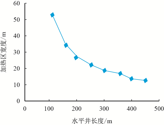
由图 2可知:当水平段越长时,加热区宽度越小,当水平段长度较短时,水平段长度的变化对加热区宽度影响越敏感;同时随着水平段长度的增加,对加热区宽度影响逐渐变小。
 |
| 图2 不同水平井长度对加热区范围的影响 Fig. 2 Effects of different horizontal length on heating area |
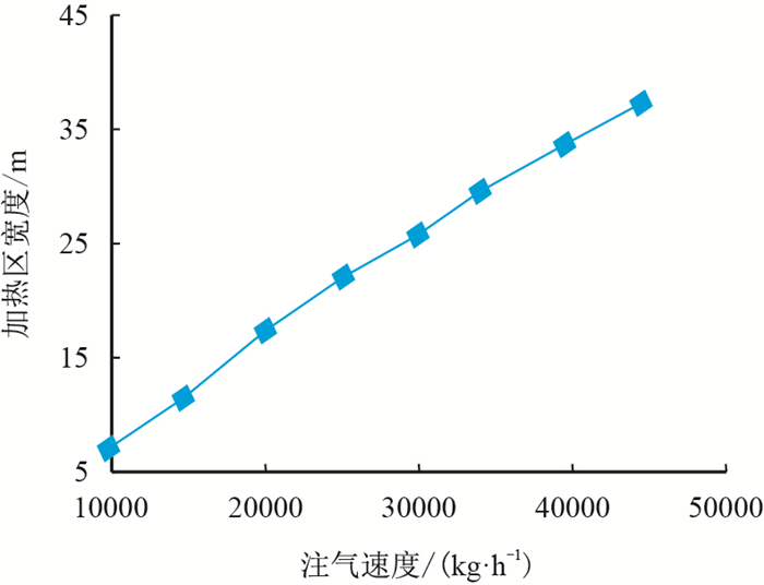
由图 3可知:随着注汽速度的不断增大,加热区宽度近似呈线性增加。
 |
| 图3 不同注汽速度对加热区宽度的影响 Fig. 3 Effects of different steam injection rate on heating zone width |
(1) 在Marx-Langenheim直井加热范围公式推导基础上,考虑了水平井沿程摩擦损失及变质量流问题,将传统加热模型简化,推导出了一个形式简单、应用方便的解析公式,应用改进的推导公式可得到相对可靠的计算结果,验证了公式的准确性,节约了计算时间,后期可在该模型的基础上进一步改进,优化模型,增加其应用范围。
(2) 在模型推导过程中,并没有考虑蒸汽超覆现象的影响,因此,在应用该模型预测厚油藏蒸汽吞吐水平段加热范围时可能造成可靠性变差的现象;但所推导模型应用于相对较短水平段可以得到相对可靠的结果,对于较长的水平段可能造成一定的误差。
| [1] |
蒲海洋, 杨双虎, 张红梅. 蒸汽吞吐效果预测及注气参数优化方法研究[J].
石油勘探与开发, 1998, 25 (3) : 52 –55.
Pu Haiyang, Yang Shuanghu, Zhang Hongmei. A method of predicting recovery effectiveness and optimizing injection parameters in steam soak[J]. Petroleum Exploration and Development, 1998, 25 (3) : 52 –55. |
| [2] |
王建勇, 王学忠, 杨勇, 等. 春风油田薄浅层超稠油水平井蒸汽驱研究[J].
特种油气藏, 2014, 21 (1) : 95 –97.
Wang Jianyong, Wang Xuezhong, Yang Yong, et al. Horizontal well steam drive for thin shallow super heavy oil reservoir in the Chunfeng Oilfield[J]. Special Oil And Gas Reservoirs, 2014, 21 (1) : 95 –97. |
| [3] |
周舰, 李颖川, 刘永辉, 等. 水平井蒸汽吞吐产能预测模型[J].
重庆科技学院学报:自然科学版, 2012, 14 (3) : 65 –67.
Zhou Jian, Li Yingchuan, Liu Yonghui, et al. A model to predict production for cyclic steam injection in horizontal wells[J]. Journal of Chongqing University of Science and Technology:Natural Science Edition, 2012, 14 (3) : 65 –67. |
| [4] |
马翠玉, 刘月田, 王春红, 等. 浅薄层稠油油藏水平井蒸汽吞吐注汽参数分析[J].
科学技术与工程, 2013, 13 (8) : 2203 –2207.
Ma Cuiyu, Liu Yuetian, Wang Chunhong, et al. The study on injection parameters about steam huff and puff of horizontal well in shallow and thin heavy oil reservoir[J]. Science Technology and Engineering, 2013, 13 (8) : 2203 –2207. |
| [5] |
倪学锋, 程林松. 水平井蒸汽吞吐热采过程中水平段加热范围计算模型[J].
石油勘探与开发, 2005, 32 (5) : 108 –112.
Ni Xuefeng, Cheng Linsong. Calculating models for heating area of horizontal wellbore in steam stimulation[J]. Petroleum Exploration and Development, 2005, 32 (5) : 108 –112. |
| [6] |
刘春泽, 程林松, 刘洋, 等. 水平井蒸汽吞吐加热半径和地层参数计算模型[J].
石油学报, 2008, 29 (1) : 101 –105.
Liu Chunze, Cheng Linsong, Liu Yang, et al. Calculating models for heating radius of cyclic steam stimulation and formation parameters in horizontal well aftersoaking[J]. Acta Petrolei Sinica, 2008, 29 (1) : 101 –105. |
| [7] |
张明禄, 刘洪波, 程林松, 等. 稠油油藏水平井热采非等温流入动态模型[J].
石油学报, 2004, 25 (4) : 62 –66.
Zhang Minglu, Liu Hongbo, Cheng Linsong, et al. Nonisothermal inflow performance model for horizontal well in heavy oil reservoir with thermal recovery[J]. Acta Petrolei Sinica, 2004, 25 (4) : 62 –66. |
| [8] |
倪学锋, 程林松, 李春兰, 等. 注蒸汽井井筒内参数计算新模型[J].
计算物理, 2005, 22 (3) : 251 –255.
Ni Xuefeng, Cheng Linsong, Li Chunlan, et al. A new model for the steam properties in steam injection wells[J]. Chinese Journal of Computation Physics, 2005, 22 (3) : 251 –255. |
| [9] |
郑舰, 陈更新, 刘鹏程. 一种新型蒸汽吞吐产能预测解析模型[J].
石油天然气学报, 2011, 33 (5) : 111 –114.
Zheng Jian, Chen Gengxin, Liu Pengcheng. A new analytical model for productivity prediction in steam soak[J]. Journal of Oil and Gas Technology, 2011, 33 (5) : 111 –114. |
| [10] |
窦宏恩, 常毓文, 于军, 等. 稠油蒸汽吞吐过程中加热半径与井网关系的新理论[J].
特种油气藏, 2006, 13 (4) : 58 –61.
Dou Hong'en, Chang Yuwen, Yu Jun, et al. A new theory of relationship between heating radius and well pattern during CSS process[J]. Special Oil and Gas Reservoirs, 2006, 13 (4) : 58 –61. |
 2015, Vol. 37


