2. 中国石油新疆油田分公司陆梁油田作业区, 新疆 克拉玛依 834000
2. The Luliang Operation Section of Xinjiang Oil Field, Petrol China, Karamay, Xinjiang 834000, China
在考虑流体饱和度、岩石物性、润湿性、驱替速度和末端效应等对相对渗透率影响的基础上[1-4],利用桓冠仁[5]等的推导结果,以更符合油藏实际的实验室非稳态相渗求解方法确定相渗曲线。在非稳态法的求解中较早的有JBN法,但是由于以差分代替求导等因素的影响,相渗曲线形态并不规整。此外还有历史拟合法求解相渗曲线,其中有指数拟合法、幂函数拟合法、三次样条拟合法和B样条拟合法等,在特定范围内适应性较好。
Krause M H[1]考虑了毛管非均质性(微尺度上的非均质性)对相对渗透率的影响,结果认为即便是低非均质性的岩石,精细尺度上非均质性的影响依然相当明显。Li Heng等[6]用EnKF法以幂函数为相对渗透率函数历史拟合出了相对渗透率曲线,由于不需要对目标函数求导而很容易应用。Sheng Q等[2]用CT成像法、核磁共振法等数值求解相渗曲线。此外还有两相渗流的非线性模型[7-11],应用逾渗理论求解相渗曲线,数值试井等,给相渗曲线的求解提供了新的方向。
本文用历史拟合法在岩芯离散调和排序的基础上,拟合逐级调和平均渗透率与累计长度的关系,并通过一定的数学方法使离散渗透率在拟合程度较好的情况下转换为随长度变化的连续渗透率,并求解出相对渗透率曲线,求解简单,结果在一定程度上是可靠的。
1 模型推导| $ \left\{ {\begin{array}{*{20}{l}} {{v_{\rm{o}}} = \frac{{K{K_{{\rm{ro}}}}}}{{{\mu _{\rm{o}}}}}\frac{{\partial p}}{{\partial x}}}\\ {v_{\rm{w}} = \frac{{K{K_{{\rm{rw}}}}}}{{{\mu _{\rm{w}}}}}\frac{{\partial p}}{{\partial x}}} \end{array}} \right. $ | (1) |
式中:
(2) 假定流体在模型中服从Buckley-Leverett一维渗流规律
| $ \left\{ {\begin{array}{*{20}{l}} {\frac{{\partial {q_{\rm{w}}}}}{{\partial x}} =- \phi \cdot A \cdot \frac{{\partial {S_{\rm{w}}}}}{{\partial t}}}\\ \frac{{\partial {q_{\rm{o}}}}}{{\partial x}} = -\phi \cdot A \cdot \frac{{\partial {S_{\rm{o}}}}}{{\partial t}} \end{array}} \right. $ | (2) |
式中:
由于
| $ {q_{\rm{t}}} =-K(x) \cdot A \cdot (\frac{{{K_{\rm{r}}}_{\rm{o}}}}{{{\mu _{\rm{o}}}}} + \frac{{{K_{{\rm{rw}}}}}}{{{\mu _{\rm{w}}}}})\frac{{\partial p}}{{\partial x}} $ | (3) |
式中:
对p关于x在区间[0,L]上积分,得
| $ \Delta p = \frac{{{q_{\rm{t}}}}}{A}\int_0^L {\frac{{{\rm{d}}x}}{{(\frac{{{K_{{\rm{ro}}}}}}{{{\mu _{\rm{o}}}}} + \frac{{{K_{{\rm{rw}}}}}}{{{\mu _{\rm{w}}}}})K(x)}}} $ | (4) |
式中:
令
| $ \alpha = \frac{1}{{{\mu _{\rm{o}}}\left( {\frac{{{K_{{\rm{ro}}}}}}{{{\mu _{\rm{o}}}}} + \frac{{{K_{{\rm{rw}}}}}}{{{\mu _{\rm{w}}}}}} \right)K(x)}} $ | (5) |
| $ \mathit{\Theta } = \int {_0^1} \frac{1}{{{\mu _{\rm{o}}}(\frac{{{K_{{\rm{ro}}}}}}{{{\mu _{\rm{o}}}}} + \frac{{{K_{{\rm{rw}}}}}}{{{\mu _{\rm{w}}}}})K(\bar x)}}{\rm{d}}\bar x = \frac{{A\Delta p}}{{q{\mu _{\rm{o}}}L}}, \bar x = x/L $ | (6) |
由于,
| $ {f_{\rm{w}}} = \frac{{\frac{{{K_{{\rm{rw}}}}}}{{{\mu _{\rm{w}}}}}}}{{\frac{{{K_{{\rm{ro}}}}}}{{{\mu _{\rm{o}}}}} + \frac{{{K_{{\rm{rw}}}}}}{{{\mu _{\rm{w}}}}}}} $ | (7) |
式中:
代入连续性方程,并用特征函数法求解,得
| $ x(S, t) = \frac{{\psi (S)}}{{\phi A}}{V_{\rm{c}}}(t) $ | (8) |
式中:x(S, t)-等饱和度面的位移函数,cm;
其中,
| $ \psi (S) = \frac{{{\rm{d}}f}}{{{\rm{d}}S}}, {V_{\rm{c}}}(t) = \int_0^t {{q_{\rm{t}}}} {\rm{d}}t $ | (9) |
无因次化后
| $ \bar x = \frac{{{V_{\rm{c}}}(t)}}{{\phi LA}}\psi (S) $ | (10) |
令
当
| $ {\psi _{\rm{e}}}(S)\overline {{V_{\rm{c}}}} = 1 $ | (11) |
将式(10)、式(11)代入式(6),并进行微分,得
| $ {\alpha _{{\psi _{\rm{e}}}}} = \frac{{{\rm{d}}\left[ {\int {_0^{{\psi _{\rm{e}}}}} \frac{1}{{{\mu _{\rm{o}}}\left( {\frac{{K{K_{{\rm{ro}}}}}}{{{\mu _{\rm{o}}}}} + \frac{{K{K_{{\rm{rw}}}}}}{{{\mu _{\rm{w}}}}}} \right)K({\psi _{\rm{e}}})}}{\rm{d}}{\psi _{\rm{e}}}} \right]}}{{{\rm{d}}{\psi _{\rm{e}}}}} = \frac{{{\rm{d}}(\mathit{\Theta }{\psi _{\rm{e}}})}}{{{\rm{d}}{\psi _{\rm{e}}}}} = \mathit{\Theta } + {\psi _{\rm{e}}}\frac{{{\rm{d}}\mathit{\Theta }}}{{{\rm{d}}{\psi _{\rm{e}}}}} $ | (12) |
从而由式(5)、式(7)可得
| $ \left\{ {\begin{array}{*{20}{l}} {{K_{{\rm{ro}}}} = \frac{{1- f}}{{\alpha K(x)}}}\\ {K_{{\rm{rw}}}} = \frac{f}{\alpha }\frac{{{\mu _{\rm{w}}}}}{{{\mu _{\rm{o}}}K(x)}} \end{array}} \right. $ | (13) |
定义:
| $ {V_{\rm{w}}} = \int_0^t {{f_{\rm{w}}}{q_{\rm{t}}}} {\rm{d}}t = {f_{{\rm{we}}}}{V_{\rm{c}}}(t)-\phi \cdot L \cdot A({S_{\rm{e}}}-{S_{{\rm{wc}}}}) $ | (14) |
式中:
且令:
| $ \nu = \frac{{\overline {{V_{\rm{o}}}} + {S_{{\rm{wc}}}}}}{{\overline {{V_{\rm{c}}}} }} = {\psi _{\rm{e}}} \cdot \overline {{S_{\rm{w}}}} = 1-f({S_{\rm{e}}}) + {S_{\rm{e}}}{\psi _{\rm{e}}} $ | (15) |
| $ \frac{{{\rm{d}}\nu }}{{{\rm{d}}{\psi _{\rm{e}}}}} = \frac{{{\rm{d}}[1-f({S_{\rm{e}}}) + {S_{\rm{e}}}{\psi _{\rm{e}}}]}}{{{\rm{d}}{\psi _{\rm{e}}}}} = {S_{\rm{e}}} = \frac{{{\rm{d}}{\psi _{\rm{e}}} \cdot \overline {{S_{\rm{w}}}} }}{{{\rm{d}}{\psi _{\rm{e}}}}} = \overline {{S_{\rm{w}}}} + \frac{{{\rm{d}}\overline {{S_{\rm{w}}}} }}{{{\rm{d}}{\psi _{\rm{e}}}}} $ | (16) |
则
| $ {f_{{\rm{we}}}} = 1-\nu + {S_{\rm{e}}}{\psi _{\rm{e}}} $ | (17) |
式中:
对于长岩芯驱替,如果要采用1 m左右的完整天然岩芯作驱替实验,从取芯技术来讲是不可行的[14],因此,国内外普遍采用常规短岩芯按一定的排列方式拼成长岩芯。为了消除岩石的末端效应,每块短岩芯之间用滤纸连接。经加拿大Hycal公司的Tomas等人论证,当岩芯足够长(1 m左右)通过在每块小岩芯之间加滤纸可将末端效应降低到一定程度。每块岩芯的排列顺序按下列调和平均方式排列。由式(18)调和平均法算出
| $ \frac{L}{{\bar K}}{\rm{ = }}\frac{{{\rm{ }}{L_1}}}{{{\rm{ }}{K_1}}} + \frac{{{\rm{ }}{L_2}}}{{{\rm{ }}{K_2}}} + \cdot \cdot \cdot {\rm{ + }}\frac{{{\rm{ }}{L_i}}}{{{\rm{ }}{K_i}}} + \cdot \cdot \cdot {\rm{ + }}\frac{{{\rm{ }}{L_n}}}{{{\rm{ }}{K_n}}} = \sum\limits_{i = 1}^n {\frac{{{\rm{ }}{L_i}}}{{{\rm{ }}{K_i}}}} $ | (18) |
利用上述岩芯排序计算方法,得到所选岩芯从出口端到入口端的排序结果(表 1)。
| 表1 岩芯逐级调和平均值与岩芯长度数据 Table 1 The data of harmonious average permeability and length of cores |
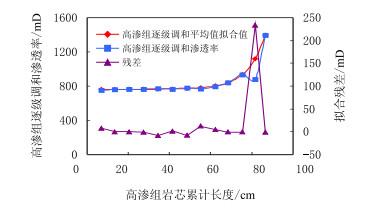
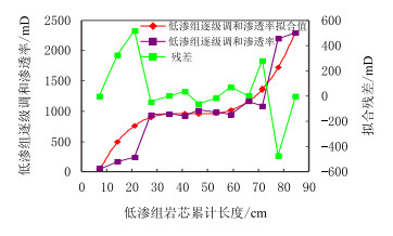
图 1和图 2分别给出高渗组和低渗组长岩芯实验数据的拟合结果。表 2给出了逐级调和平均值与岩芯长度之间关系的拟合结果。可以看出,两组拟合效果较好,由于低渗组拟合渗透率级差较大(>100),除个别点外使得RMSE (误差均方根)偏大外,拟合效果较好,可以满足预测要求。
 |
| 图1 低渗组拟合曲线与残差图 Fig. 1 The fitted curve and residuals of lower permeable cores |
 |
| 图2 高温高压岩芯滤失仪简易图 Fig. 2 Diagram of high temperature and pressure core filtration instrumentation |
| 表2 逐级调和平均值与岩芯长度拟合结果 Table 2 The fitted results of harmonious average permeability and accumulated length of cores |
由于拟合得到的值是调和渗透率,需将调和平均值转换为单块岩芯的渗透率值,由调和平均式得
| $ \left\{ {\frac{1}{{{K_k}}}} \right. = \left( {\frac{{\sum\limits_{j = 1}^{n-k + 1} {{l_j}} }}{{\overline {{K_k}} }}{\rm{-}}\frac{{\sum\limits_{j = 1}^{n-k} {{l_j}} }}{{\overline {{K_{k + 1}}} }}} \right){\rm{ }}/{l_k}{\kern 1pt} {\kern 1pt} {\kern 1pt} {\kern 1pt} k \le n - {\rm{1}} $ | (19) |
式中:
n-岩芯总块数;
k-从入口端到出口端岩芯序号。
将单个岩芯简化为质点,即
| $ \frac{1}{{K(x)}} = {\rm{ }}\left\{ {\begin{array}{*{20}{c}} {\frac{{{\rm{d}}(\frac{x}{{761{{\rm{e}}^{0.0001231x}} + 0.02119{{\rm{e}}^{0.1189x}}}})}}{{{\rm{d}}x}}, 高渗组}\\ {\frac{{{\rm{d}}(\frac{x}{{0.01983{x^3}-2.591{x^2} + 111.7x-629.3}})}}{{{\rm{d}}x}}, 低渗组} \end{array}} \right., x > 0 $ | (20) |
化简后,得
| $ \frac{1}{{K(x)}} = \left\{ {\begin{array}{*{20}{c}} {\frac{{ - \left[ {{{\rm{e}}^{0.0001231x}}(9.368x - {{7.6110}^4}) + {{\rm{e}}^{0.1189x}}(0.2519x - 2.119)} \right]}}{{{{({{7.6110}^3}{{\rm{e}}^{0.0001231x}} + 0.2119{{\rm{e}}^{0.1189x}})}^2}}},高渗组}\\ {\frac{1}{{0.01983{x^3} - 2.591{x^2} + 111.7x - 629.3}} - \frac{{\left( {0.05949{x^2} - 5.182x + 117.0} \right)}}{{\left( {0.01983{x^3} - 2.591{x^2} + 111.7x - 629.3} \right)}},低渗组} \end{array}} \right., > 0 $ | (21) |
(1) 作
(2) 计算
| $ \mathit{\Theta }{\rm{ = }}\frac{{\Delta p}}{Q} \times \frac{A}{{{\mu _{\rm{o}}} \cdot L}}, {\psi _{\rm{e}}}{\rm{ = }}\frac{1}{{\bar V}}, {S_{{\rm{wa}}}}{\rm{ = }}\overline {{V_{\rm{o}}}} {\rm{ + }}{S_{{\rm{wc}}}} $ | (22) |
式中:Q-总产液量,cm3/s;
(3) 用公式逼近
| $ \mathit{\Theta } = {a_1}{{\rm{e}}^{{b_1}x}} + {c_1}{{\rm{e}}^{{d_1}x}} $ | (23) |
| $ {S_{{\rm{wa}}}} = {a_2}{{\rm{e}}^{{b_2}x}} + {c_2}{{\rm{e}}^{{d_2}x}} $ | (24) |
拟合得[15]
| $ {a_1} = 0.5343, {b_1} = 0.04398, {c_1} =-0.4338, {d_1} =-0.5202 $ |
| $ {a_2} = 0.6901, {b_2} =-0.1526, {c_2} =-0.2811, {d_2} = 0.02575 $ |
由上式可知
| $ {S_{\rm{e}}} = {S_{{\rm{wa}}}} + {\psi _{\rm{e}}}\frac{{{\rm{d}}\overline {{S_{\rm{w}}}} }}{{{\rm{d}}{\psi _{\rm{e}}}}} = {a_2}{{\rm{e}}^{{b_2}{\psi _{\rm{e}}}}}(1 + {b_2}{\psi _{\rm{e}}}) + \\ {c_2}{{\rm{e}}^{{d_2}{\psi _{\rm{e}}}}}(1 + {d_2}{\psi _{\rm{e}}}) $ | (25) |
| $ \alpha = \frac{{{\rm{d}}(\Theta {\psi _{\rm{e}}})}}{{{\psi _{\rm{e}}}}} = {a_1}{{\rm{e}}^{{{\rm{b}}_{\rm{1}}}{\psi _{\rm{e}}}}}(1 + {b_1}{\psi _{\rm{e}}}) + \\ {c_1}{{\rm{e}}^{{d_1}{\psi _{\rm{e}}}}}(1 + {d_1}{\psi _{\rm{e}}}) $ | (26) |
| $ f = 1-\nu + {S_{\rm{e}}}{\psi _{\rm{e}}} = 1 + {\rm{ }}\psi _{\rm{e}}^{\rm{2}} \times \frac{{{\rm{d}}\overline {{S_{\rm{w}}}} }}{{{\rm{d}}{\psi _{\rm{e}}}}} = \\ 1 + {\rm{ }}\psi _{\rm{e}}^{\rm{2}}({a_1}{b_1} \times {{\rm{e}}^{{b_1}{\psi _{\rm{e}}}}} + {c_1}{d_1} \times {{\rm{e}}^{{d_1}{\psi _{\rm{e}}}}}) $ | (27) |
结合式(13)、式(21),可求得水驱油过程相渗曲线。
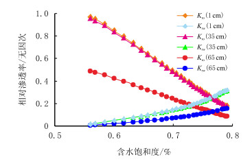
2.1 高渗组长岩芯不同位置相对渗透率曲线特征图 3给出高渗组长岩芯距注入端1.0,35.0,65.0 cm拟合的相对渗透率曲线。由图 3可以看出:
 |
| 图3 高渗组岩芯1.0,35.0,65.0 cm处相对渗透率曲线 Fig. 3 The relative permeability curve of more permeable cores in 1, 35, 65 cm |
(1) 不同位置等渗点相对渗透率几乎相等,在0.7606~0.7639。不同位置的点几乎在相同的含水饱和度上两相渗滤能力达到最弱,这主要是由于岩芯同一润湿性、在统一的温度、压力系统下两相的渗流特性有一定的统一性。油水相相对渗透率随距入口距离的增加而渗滤能力不断减小。
(2)
(3) 驱替后段,驱替相地层水流动能力增加,形成一定的冲洗效果,再加上两相渗滤能力的减弱,有更多的剩余油被驱替出来,虽然油量较少但下降较缓,驱替效果在一定程度上是可观的。
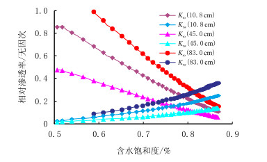
2.2 低渗组长岩芯不同位置相对渗透率曲线特征图 4给出低渗组长岩芯距注入端10.8,45.0,83.0 cm处拟合的相对渗透率曲线。由图 4可以看出:
 |
| 图4 低渗组岩芯10.8,45.0,83.0 cm处相对渗透率曲线 Fig. 4 The relative permeability curve of low permeable cores in 10.8, 45.0, 83.0 cm |
(1) 不同位置等渗点相对渗透率几乎相等,但其值在0.8114~0.8164 (大于高渗组长岩芯)。不同位置的点几乎在相同的含水饱和度上两相渗滤能力达到最弱,这主要是由于岩芯同一润湿性、在统一的温度、压力系统下两相的渗流特性有一定的统一性。
(2) 同样,油水相相对渗透率随距入口距离的增加而渗滤能力不断减小。这也是由于从入口到出口的压力梯度分布所造成的,距入口越远的点,其与出口间的压差就越小,从出口端冲刷过来的泥质颗粒便越会在出口附近被阻滞、沉降下来堵塞孔道,引起两相渗滤能力下降。
3 结论(1) 在约翰逊公式的基础上,根据桓冠仁、沈平平计算公式,考虑了实验室长岩芯驱替中,岩芯渗透率随岩芯长度的变化,并拟合出岩芯渗透率随调和平均渗透率的变化趋势。
(2) 利用渗透率与岩芯长度的变化关系,可求解出长岩芯驱替过程中,长岩芯不同位置的相对渗透率变化曲线。
(3) 拟合结果显示,在调和渗透率与岩芯长度拟合差的点,相渗曲线可能会产生一定的变形,但是对调和平均值与累计长度拟合好的点而言,相渗规律可靠。所得规律能够用于分析长岩芯驱替对渗流特征的影响。
| [1] | Krause M H. Modeling and investigation of the influence of capillary heterogeneity on relative permeability[C]. SPE 160909, 2012. |
| [2] | Sheng Q, Thompson K E, Fredrich J T. Numerical prediction of relative permeability from micro CT images:comparison of steady-state versus displacement methods[C]. SPE 147431, 2011. |
| [3] | Bennion D B, Thomas F B. Recent improvements in experimental and analytical techniques for the determination of relative permeability data from unsteady state flow experiments[C]//10th Techncial Conference and Exposition, Port of Spain, Trinidad, SPE 1991. |
| [4] |
赵春鹏, 岳湘安. 特低渗透油藏超前注水长岩芯实验研究[J].
西南石油大学学报:自然科学版, 2011, 33 (3) : 105–108.
Zhao Chunpeng, Yue Xiang'an. Long-core experimental study on advance water injection of extralow permeability reservoir[J]. Journal of Southwest Petroleum University:Science & Technology Edition, 2011, 33 (3) : 105–108. |
| [5] |
桓冠仁, 沈平平. 一种非稳态油水相对渗透率曲线计算方法[J].
石油勘探与开发, 1982 (2) : 52–58.
Huan Guanren, Shen Pingping. Calculating relative permeability[J]. Petroleum Exploration and Development, 1982 (2) : 52–58. |
| [6] | Li Heng, Chen Shengnan, Yang Daoyong, et al. Ensemble-based relative permeability estimation using B-spline model[J]. Transport in Porous Media, 2010, 85 (3) : 703–721. DOI:10.1007/s11242-010-9587-7 |
| [7] |
邓英尔, 刘慈群. 两相流体非线性渗流模型及其应用[J].
应用数学和力学, 2003, 24 (10) : 1049–1056.
Deng Ying'er, Liu Ciqun. Mathematical model of twophase fluid nonlinear flow in low-permeability porous media with applications[J]. Applied Mathematics and Mechanics, 2003, 24 (10) : 1049–1056. |
| [8] |
王坤, 张烈辉. 考虑应力敏感超低渗油藏油水相对渗透率的计算[J].
石油天然气学报, 2011, 33 (11) : 117–119.
Wang Kun, Zhang Liehui. Calculation of relative permeability of extra-low permeability reservoirs considering stress sensitivity[J]. Journal of Oil and Gas Technology, 2011, 33 (11) : 117–119. |
| [9] |
王金勋, 刘庆杰, 杨普华, 等. 应用逾渗理论计算非稳态法油水相渗曲线[J].
石油勘探与开发, 2001, 28 (2) : 79–82.
Wang Jinxun, Liu Qingjie, Yang Puhua, et al. Calculating the relative permeability from displacement experiments based on percolation theory[J]. Petorleum Exploration and Development, 2001, 28 (2) : 79–82. |
| [10] |
向祖平, 张烈辉, 陈辉, 等. 相渗曲线对油水两相渗流数值试井曲线的影响[J].
西南石油大学学报, 2007, 29 (4) : 74–78.
Xiang Zuping, Zhang Liehui, Chen Hui, et al. Influnce of the relative permeability curve on numerical well test curve of oil-water-phase flow[J]. Journal of Southwest Petroleum Univesity, 2007, 29 (4) : 74–78. |
| [11] |
杨小平. 精确计算相对渗透率的方法[J].
石油勘探与开发, 1998, 25 (6) : 63–66.
Yang Xiaoping. A method to calculate the relative permeability accurately[J]. Petorleum Exploration and Development, 1998, 25 (6) : 63–66. |
| [12] | Johnson E F, Bossler D P, Bossler V O. Calculation of relative permeability from displacement experiments[C]. SPE 1023, 1959. |
| [13] |
王学武, 杨正明, 时宇, 等. 核磁共振研究低渗透砂岩油水两相渗流规律[J].
科技导报, 2009, 27 (15) : 56–58.
Wang Xuewu, Yang Zhengming, Shi Yu, et al. Experimental study of water-oil two-phase fluid flow in low permeability reservoir by nuclear magnetic resonance[J]. Science & Technology Review, 2009, 27 (15) : 56–58. |
| [14] | 李士伦, 张正卿, 冉新权. 注气提高石油采收率技术[M]. 成都: 四川科学技术出版社, 2001 . |
| [15] | 张志涌. 精通Matlab R2011a[M]. 北京: 北京航空航天大学出版社, 2011 . |
 2014, Vol. 36

