


2. Hypervelocity Aerodynamics Institute of China Aerodynamics Research and Development Center, Mianyang Sichuan 621000, China
2. 中国空气动力研究与发展中心超高速空气动力研究所, 四川 绵阳 621000
The reentry vehicle with a large angle of attack and hypersonic speed flies in the chemical non-equilibrium thermal environment for a long time. The thermal environment has four distinctive characteristics, including high enthalpy, low pressure, low heat flux and chemical non-equilibrium flow, which provide favorable conditions for transiting the vehicle's thermal protection system from ablative to non-ablative type. The surface catalytic and anti-oxidation characteristics of non-ablative thermal protection materials reduce the surface aerodynamic heat load and control the appearance of the vehicle[1-3]. Therefore, the objective and effective evaluations of catalytic and anti-oxidation properties are of utmost important in the selection of thermal protection materials. Moreover, the optimization design of thermal protection systems are based on these criterions.
At present, the rule of Three-Parameter-Simulation and the method of Stagnation-point-Simulation are generally adopted to investigate the performance of thermal protection materials. The Three-Parameter-Simulation, consisting of total enthalpy at the outer edge of boundary layer, wall pressure and heat flux of stagnation-point, suits with the heat transfer in the chemical equilibrium boundary layer[4-13]. In order to apply Three-Parameter-Simulation to simulate the heat transfer in the chemical frozen or non-equilibrium boundary layer (the flow has reached the chemical equilibrium state at the outer edge of boundary layer), the conception of "local heat transfer simulation" (LHTS[14]) is presented. The new three-parameters are corrected as total enthalpy, velocity gradient at the outer edge of boundary layer, and wall pressure on the stagnation-point.
However, if the chemical state is non-equilibrium at the outer edge of boundary layer, the Three-Parameter-Simulation is impossible to obtain the material's effective service performance from the ground simulation test. Hence, in order to improve the service performance of non-ablative thermal protection materials, the fourth parameter simulation on the chemical non-equilibrium degree of the outer edge of boundary layer should be introduced into the aforementioned Three-Parameter-Simulation.
The current study analyzes the main flow field parameters and the effect of the stagnation-point heat flux of hypersonic blunt body on the basis of Fay-Riddell formula[15]and Goulard formula[16]. Subsequently, the paper introduces the simulated environmental characteristics provided by ground high-enthalpy simulation facility and highlights main differences from real flight environment. By combining the differences between simulation and flight tests, the validity of Three- and Four-Parameter-Simulations are theoretically analyzed. Moreover, the validity of simulation parameters selection has been demonstrated by a numerical simulation method. If the ratio of dissociation and total enthalpy at the outer edge of boundary layer cannot be simulated in the high enthalpy simulation facility, the stagnation-point heat flux of spacecraft cannot be simulated by the simulation test.
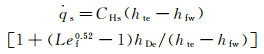
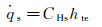
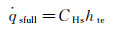
1 Analysis of the influence parameters of the stagnation-point heat flux for hypersonic vehicle 1.1 Influence parameters of the stagnation-point heat fluxFor an axisymmetric blunt body, its stagnation-point heat flux can be determined by using different formulae, according to the different chemical states, within the boundary layer of the flow around the body. The stagnation-point heat flux within an equilibrium boundary layer can be determined by using Fay-Riddell formula (Tw≤2000K and the wall dissociation enthalpy hDw=0):
 (1a)
(1a)
where CHs is the heat transfer coefficient of the stagnation point, hte is the total enthalpy at the outer edge of boundary layer, hfw=cpfTw is the wall frozen enthalpy (Tw and cpf are the wall temperature and the equivalent specific heat capacity, respectively.), hDe=∑hi0Cie is dissociation enthalpy at the outer edge of boundary layer (Cie and hi0 are the concentration at the outer edge of boundary layer and the formation enthalpy of i species, respectively.), Lef is the frozen Lewis number.
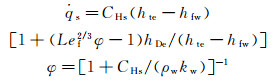
The stagnation-point heat flux of the frozen boundary layer is related to the rate constant of vehicle's surface catalytic reaction, kw, which can be determined by using Goulard formula:
 (1b)
(1b)
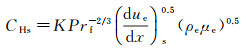
The CHs is,
 (2)
(2)
where the frozen Prandtl number, Prf, is the velocity gradient at the stagnation point, (due/dx)s is the velocity gradient at the outer edge of boundary layer, ρe and μe are the mix gas density and the viscosity coefficient at the outer edge of boundary layer, respectively.
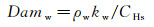
According to the Fay-Riddell formula, the K value equals to 0.763, whereas the Goulard formula results in a K value of 0.664. The Damköhler number (Damw) of the surface catalysis reaction can be defined as:
 (3)
(3)
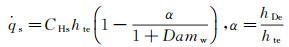
For the approximation of Lef=Prf=1 and hte
 (4a)
(4a)
 (4b)
(4b)
where α is the ratio of dissociation to total enthalpy at the outer edge of boundary layer.
Equation (2) indicates that CHs is controlled by (due/dx)s, ρe and μe. Because both of the mix gas density and viscosity coefficient are functions of enthalpy, pressure and species concentration (ρ=fρ(p, h, Ci) and μ=fμ(p, h, Ci)). At the chemical equilibrium outer edge of boundary layer, ρe and μe are the function of pe, hte. For the chemical non-equilibrium at the outer edge of boundary layer, the functions are ρe=fρ(pe, hte, Cie) and μe=fμ(pe, hte, Cie), where pe is pressure at the outer edge of boundary layer, which equals to the stagnation pressure, ps.
Hence, if the outer edge of the chemidcal frozen boundary layer is chemical equilibrium, the stagnation-point heat flux is influenced by three field parameters, hte, ps and (due/dx)s. If the outer edge of boundary layer is chemical non-equilibrium, the stagnation-point heat flux is also influenced by a fourth field parameter, α.
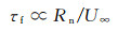
1.2 Coupling effect between dissociation enthalpy and catalytic reaction rate on the stagnation-point heat fluxWithin the stagnation-point domain, the dissociation enthalpy is controlled by the vehicle's head radius and flight orbit. In addition, the flow characteristic time (τf) around the body is proportional to the vehicle's nosetip radius (Rn), given by the following expression:
 (5)
(5)
As a result, under the specific flight height and velocity, τf decrease with Rn. However, τf of the ionization and dissociation reactions remain constant after normal shock. Therefore, the hDe exhibits a direct relationship with Rn. For convenience, the stagnation-point heat transfer theory for frozen boundary layer is used to analyze the coupling effect of dissociation enthalpy and the rate constant of surface catalytic reaction on the stagnation-point heat flux.
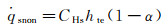
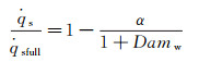
Because the maximum of α equals to 1, while Damw equals to 100, according to Goulard formula (equation (4b)), 


 (6a)
(6a)
 (6b)
(6b)
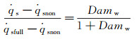
For a partially-catalytic surface, 0 < Damw < 100, the relationship between the heat flux of partially-and the fully-catalytic surface can be given as follows:
 (7)
(7)
According to the above analysis, the stagnation-point heat flux of the limited catalytic surface is directly influenced by α and the catalytic reaction Damköhler number of the material surface, Damw. Fig. 1 presents the variation of stagnation-point dimensionless heat flux 

|
Fig.1 The variation of   |
For the fully-catalytic surface, the stagnation-point heat flux is not influenced by dissociation enthalpy. However, for the partially-catalytic surface, the stagnation-point heat flux shows linear relationship with dissociation enthalpy. In conclusion, the stagnation-point heat flux decreases with the increasing of dissociation enthalpy, which implies that the surface catalytic characteristics of non-ablative material have a significant impact on the stagnation-point heat flux. Therefore, it is indispensable to consider the dissociation enthalpy in the ground simulation test study for the service performance evaluation of these materials.
In summary, the stagnation-point heat flux affected by the principal flow field factors include hte, ps, (due/dx)s and α. The first three parameters affect the stagnation-point heat flux within the chemical frozen and non-equilibrium boundary layer whose outer edge is chemical equilibrium. If the outer edge of boundary layer is chemical non-equilibrium, the stagnation-point heat flux is directly influenced by α.
2 Difference between ground simulation and flight environmentThe arc-heated wind tunnel (AHWT) and induction-heated wind tunnel (IHWT) are main facilities to perform ground simulation research to evaluate the performance of thermal protection materials. Such kind of facility utilizes arc or induction heating to heat the in-chamber gas to the pre-set enthalpy value. Then, the in-chamber high-temperature gas gets dissociated and ionized and air dissociation enthalpy accounts for 10%~70% of the total enthalpy (see Fig. 2), with the enthalpy range of 4~32 MJ/kg.

|
| Fig.2 The equilibrium air α changed with pressure and enthalpy 图 2 平衡下α随压力和焓值的变化 |
When the in-chamber high-enthalpy air passes through the supersonic nozzle, a complex three-body collision reaction between the dissociated atoms occurs in the nozzle contraction section, which gradually reduces the dissociation enthalpy in the fluid. With the increase of flow rate, the frozen point of chemical flow state occurs at some positions in the nozzle's expansion section (nozzle with a higher Mach number), resulting in the dissociation enthalpy of nozzle jet is higher than the equilibrium state.
In order to quantitatively analyze the flow characteristics in the supersonic nozzles, the flow characteristics of the supersonic nozzles in the arc-heated and induction-heated wind tunnels are calculated, respectively. Table 1 presents the parameters of the in-chamber gas and the geometric parameters of the nozzle.
| AHWT | |
| In-chamber pressure/kPa | 180.0 |
| In-chamber enthalpy/(kJ·kg-1) | 2.3×10⁴ |
| Nozzle throat/mm | Φ30.0 |
| Nozzle outlet/mm | Φ200.0 |
Along the axis of the supersonic nozzle, the distribution of CO and CN in the chemical equilibrium and the non-equilibrium are shown in Fig. 3(a). Besides, the distribution of CO and CN in the chemical equilibrium and the non-equilibrium states, the distribution of temperature (T) and velocity (U) of jet flow, and the distribution of α and ht along the cross-section of the nozzle are shown in Fig. 3(b), (c) and (d), respectively. The numerical simulation results exhibit that under the supersonic conditions, the jet provided by the ground simulation equipment exhibits a severe chemical non-equilibrium state.

|
| Fig.3 Distribution of parameters along the axis and exit of the AHWT nozzle 图 3 各参数沿着电弧风洞喷管轴线和出口的分布 |
Therefore, the ground simulation environment is able to provide the same total enthalpy, stagnation-point pressure and velocity gradation as those in the actual flight environment. The main difference between simulated flow field and flight environment is the dissociation enthalpy (because the dissociation enthalpy is zero before the shock wave in the real flight environment).
3 Selection of ground simulation parametersTo study the service performance of non-ablative thermal protection materials in a chemical non-equilibrium environment, the FPS should be applied in the ground test simulation. The Four-Parameter-Simulation includes stagnation pressure, stagnation-point velocity gradient, total enthalpy and dissociation enthalpy, and the ground test results can reproduce the aerodynamic heat load at the stagnation-point region under the flight conditions.
When the flight environment parameters (remarked by superscript F) and simulation environment parameters (remarked by superscript S) are determined, the crucial step is to determine the effective size of the test piece. The following relationships between the total enthalpy, stagnation-point pressure, stagnation-point velocity gradients, flight velocity (U∞F), free flow density (ρ∞F) and pressure (p∞F) and effective spacecraft nosetip radius (RnF) under the flight conditions should be used for this purpose.
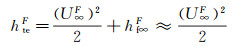
Total enthalpy:
 (8)
(8)
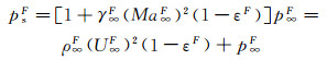
Stagnation-point pressure:
 (9)
(9)
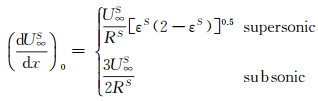
Stagnation-point velocity gradient:
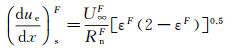 (10)
(10)
where ε refers to the density ratio of gas "before" and "after" the shock wave, ε=ρ∞/ρe. The value has the following relationship with the Mach number Ma∞, and the ratio of specific heat capacities of the incoming flow γ∞.
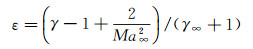 (11)
(11)
In a ground simulation environment, the jet energy is consisting of gas kinetic energy, internal energy and dissociation energy. The total enthalpy of gas flow can be determined by the following equation:
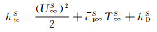 (12)
(12)
The jet stagnation-point pressure can be determined from the given expression:
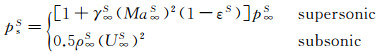 (13)
(13)
The velocity gradient, within a stagnation-point domain, can be determined according to the following relationship:
 (14)
(14)
According to the relationships of hteF=hteS, psF=psS and (dueF/dx)s=(dueS/dx)s, the effective dimension in the ground simulation environment can be given as following:
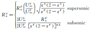 (15)
(15)
To simulate the performance of material with a fully-catalytic surface, the Three-Parameter-Simulation (consisting of stagnation-point pressure, stagnation-point velocity gradient and total enthalpy) can provide the required data. However, for the material with partially-catalytic surface, dissociation enthalpy should be also considered.
In order to verify the validity of parameter selection, the stagnation-point heat flux of vehicle under specific flight condition is compared with the stagnation-point heat flux of test piece under the corresponding ground simulation conditions. With the help of CFD, the selected flight conditions are shown in Table 2.
| RnF/mm | U∞F/(m·s-1) | p∞F/Pa | T∞F/K | CFO2 | CFN2 | COF | CNF | CNOF | |
| Case 1 Case 2 |
200 35 |
6930 | 8 | 229.5 | 0.234 | 0.766 | 0 | 0 | 0 |
According to the flow field parameters of AHWT and formulae of Three-Parameter-Simulation, the dimensions and shapes of test samples are determined and listed in Table 3, RnS=26.65mm for hemisphere-headed cylinder (corresponding to RnF=35mm) and RnS=35mm for flat-head cylinder (corresponding to RnF=200mm) and the surface temperature is Tw= 350K.
| RnS/mm | U∞S(m·s-1) | p∞S/Pa | T∞S/K | CSO2 | CSN2 | COS | CNS | CNOS | |
| Case 1 | 35 | 4654 | 107 | 920 | 0 | 0.508 | 0.234 | 0.258 | 0 |
The simulation results of stagnation-point conduction heat flux (

| RnF/mm | pFs/Pa | Heat flux of full surface catalysis /(kW·m-2) | Heat flux of non surface catalysis /(kW·m-2) |  |
||||||
 |
 |
 |
 |
 |
 |
|||||
| Case 1 | 200 | 5540 | 1096 | 830 | 1926 | 1089 | 0 | 1089 | 0.565 | |
| Case 2 | 35 | 5540 | 3247 | 1531 | 4778 | 3176 | 50 | 3176 | 0.665 | |
| RnF/mm | psF/Pa | Heat flux of full surface catalysis /(kW·m-2) | Heat flux of non surface catalysis /(kW·m-2) |  |
||||||
 |
 |
 |
 |
 |
 |
|||||
| Case 1 | 35.00 | 5500 | 1118 | 834 | 1952 | 1120 | 0 | 1120 | 0.574 | |
| Case 2 | 26.65 | 5500 | 2483 | 2391 | 4874 | 2229 | 0 | 2229 | 0.457 | |
 |
 |
 |
 |
 |
|
| Case 1 | 2.01% | 0.482% | 1.35% | 2.85% | 2.85% |
| Case 2 | -23.53% | 56.17% | 2.01% | -29.82% | -29.82% |

|
| Fig.4 Parameter distributions on the stagnation-point line of the blunt body sample with RnF=200mm 图 4 钝头试样(RnF=200mm)驻点线上参数分布 |

|
| Fig.5 The parameter distributions on RnF=35mm vehicle and stagnation-point line of the test sample 图 5 球头试样(RnF=35mm)驻点线上参数分布 |

|
Fig.6 The variation of 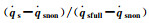 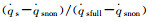 |
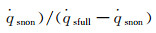
According to equation 6(a) and (b), the α can be determined by the non-catalytic and fully-catalytic stagnation-point heat flux:
 (16)
(16)
According to equation (7) and (16):
 (17)
(17)
The dimensionless stagnation-point heat flux equation is only determined by the Damköhler number of surface catalytic reaction and independent on α. Fig. 6 demonstrates the variation of 
According to the condition of Three-Parameter-Simulation, there are DamwF=DamwS and 
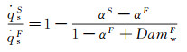 (18)
(18)
It indicates that the value of 


|
Fig.7 The variation of   |
According to equation (18), in the chemical frozen boundary layer, only under the condition of αS=αF, the simulation performed by Three-Parameter-Simulation method is valid. Therefore, for the stagnation-point heat transfer in the chemical frozen boundary layer, a reasonable simulation method should consist of total enthalpy, pressure, velocity gradient and the ratio of dissociation enthalpy to total enthalpy at the outer edge of boundary layer, that is the Four-Parameter-Simulation. In general, αF < αS results in that the value of stagnation-point heat flux produced by ground simulation is smaller than that in the real flight environment.
4 Conclusions(1) When the outer edge of boundary layer is in the chemical equilibrium state, the Three-Parameter-Simulation is valid in both the ground simulation and real flight environment.
(2) When the outer edge of boundary layer is in the non-equilibrium state, the Three-Parameter-Simulation will result in heat flux reduction in both the ground simulation and real flight environment, but the Four-Parameter-Simulation adopted in the test can compensate this problem.
(3) While the dissociation enthalpy cannot be simulated, the only effective way to solve the problem of not being able to simulate the dissociation enthalpy is to determine the difference between the simulated stagnation point heat flux of partially-catalytic surface and the stagnation point heat flux in flight. The simulation results are then extrapolated to the flight environment via mutual verification between the ground simulation and the flight test.
| [1] | Matthew M, Eric M, Ronald P. Effect of surface catalysis on measured heat transfer in expansion tunnel facility[R]. AIAA-2012-0651, 2012. Matthew M, Eric M, Ronald P. Effect of surface catalysis on measured heat transfer in expansion tunnel facility[R]. AIAA-2012-0651, 2012. |
| [2] | Kurotaki T. Construction of catalytic model on SiO2-based surface and application to real trajectory[R]. AIAA-2000-2366, 2000. Kurotaki T. Construction of catalytic model on SiO2-based surface and application to real trajectory[R]. AIAA-2000-2366, 2000. |
| [3] | Voinov L, Zalogin G N, Lunev V V, et al. Comparative analysis of laboratory and full-scale data on the catalycity of the heat shield for the Bor and Buran orbital vehicles[J]. Cosmonautics and Rocket Production, 1994(2): 51–57. |
| [4] | Kolodziej P, Stewart D A. Nitrogen recombination on high-temperature reusable surface insulation and the analysis of its effect on surface catalysis[R]. AIAA-1987-1637, 1987. Kolodziej P, Stewart D A. Nitrogen recombination on high-temperature reusable surface insulation and the analysis of its effect on surface catalysis[R]. AIAA-1987-1637, 1987. |
| [5] | Scott C D. Catalytic recombination of nitrogen and oxygen on hig-temperature reusable surface insulation[R]. AIAA-1980-1477, 1980. Scott C D. Catalytic recombination of nitrogen and oxygen on hig-temperature reusable surface insulation[R]. AIAA-1980-1477, 1980. |
| [6] | Stewart D A, Rakich J V, Lanfranco M J. Catalytic surface effects experiments on space shuttle[R]. AIAA-1981-1143, 1981. Stewart D A, Rakich J V, Lanfranco M J. Catalytic surface effects experiments on space shuttle[R]. AIAA-1981-1143, 1981. |
| [7] | Rakich J V, Stewart D A, Lanfranco M J. Results of a flight experiment of the catalytic efficiency of the space shuttle heat shield[R]. AIAA-1982-944, 1982. Rakich J V, Stewart D A, Lanfranco M J. Results of a flight experiment of the catalytic efficiency of the space shuttle heat shield[R]. AIAA-1982-944, 1982. |
| [8] | Zoby E V, Gupta R N, Simmonds A L. Temperature dependent reaction-rate expression for oxygen recombination at shuttle entry conditions[R]. AIAA-1984-224, 1984. Zoby E V, Gupta R N, Simmonds A L. Temperature dependent reaction-rate expression for oxygen recombination at shuttle entry conditions[R]. AIAA-1984-224, 1984. |
| [9] | Shim J L, Moss J N, Simmonds A L. Viscous-shock-layer heating analysis for the shuttle windward symmetry plane with surface finite catalytic recombination rates[R]. AIAA-1982-0842, 1982. Shim J L, Moss J N, Simmonds A L. Viscous-shock-layer heating analysis for the shuttle windward symmetry plane with surface finite catalytic recombination rates[R]. AIAA-1982-0842, 1982. |
| [10] | Jumper E J. Recombination of oxygen and nitrogen on silica-based thermal protection surfaces: mechanism and implication[R]. AIAA-1993-477, 1993. Jumper E J. Recombination of oxygen and nitrogen on silica-based thermal protection surfaces: mechanism and implication[R]. AIAA-1993-477, 1993. |
| [11] | Melin G A, Madix R J. Energy accommodation during oxygen atom recombination on metal surface[J]. Transactions of the Faraday Society, 1971, 67: 198–211. DOI:10.1039/tf9716700198 |
| [12] | Halpern B, Rosner D E. Chemical energy accommodation at catalyst surface. Flow reactor studies of the association of nitrogen atoms on metals at high temperatures[J]. Journal of the Chemical Society Faraday Transactions, 1978, 74: 1883–1912. DOI:10.1039/f19787401883 |
| [13] | Kolesnikov A F. The concept of local simulation for stagnation point heat transfer in hypersonic flow: applications and validation[R]. AIAA-2000-2515, 2000. Kolesnikov A F. The concept of local simulation for stagnation point heat transfer in hypersonic flow: applications and validation[R]. AIAA-2000-2515, 2000. |
| [14] | Kovalev V L, Kolesnikov A F. Experimental and theoretical simulation of heterogeneous catalysis in aerothermochemistry(a review)[J]. Fluid Dynamics, 2005, 40(5): 669–693. DOI:10.1007/s10697-005-0106-4 |
| [15] | Fay J A, Riddell F R. Theory of stagnation point heat transfer in dissociated air[J]. Journal of the Aeronautical Sciences, 1958, 25(2): 73–85. |
| [16] | Goulard R. On catalytic recombination rates in hypersonic stagnation on heat transfer[J]. Journal of Jet Propulsion, 1958, 28(11): 737–745. DOI:10.2514/8.7444 |