


2. 北京大学工学院 力学与工程科学系 湍流与复杂系统国家重点实验, 北京 100871
2. State Key Lab. for Turbulence Complex and Systems, Department of Mechanics and Engineering Science, College of Engineering, Peking University, Beijing 100871, China
High temperature (up to 1700K[1]) gases such as the combustion reaction products of the pure oxygen or air with the fuels,e.g.,hydrogen,methane,ethanol and kerosene can be adopted as the working media in hypersonic wind tunnel experiments. However,the complexity of combustion process makes it difficult to accurately predict the concentration of each component of the combustion gases. In experiments,the characteristic parameters,such as the specific heat and density,are important but cannot be predefined. For example,the specific heat ratio,the ratio of the molar heat capacity at constant pressure to the molar heat capacity at constant volume,is crucial in evaluating the Mach number,as one of the performance indices of a supersonic wind tunnel nozzle.
Commonly there are two methods to obtain γ — one is the empirical method usually adopted in the flow field calculation of engine exhaust system[2]; another is the composition analysis method used in calibration of the thermal structure of a hypersonic wind tunnel[3]. The empirical method calculates for the components of combustion gases based on an empirical combustion efficiency formula under a similar combustion condition. Thus the resultant γ is an approximation under a similar flow condition and its uncertainty is intrinsically unpredictable. The composition analysis method calculates according to the quantities of the components of the combustion gases by analyzing the gas chromatography at different temperatures. Complex gas chromatography is essential for accurate measurement of the quantities of all components of the combustion gases[4].
In addition to the complicated facilities of chromatography analysis,it is a real challenge for one to probe the temperature of the combustion gases in the heat hypersonic flow[5]. Hence,this method has not been widely employed.
This paper presents a new technique for efficiently obtaining the accurate γ of the combustion gas in hypersonic flow field. This technique is proposed to utilize the relations of the fluid densities before and after a normal shock wave induced by the Pitot tube. Feasibility of this method is testified in details. The advantages of this method are the simplicity and economy of the instruments and the high precision of the resultant data. 1 Principle of measuring γ
When Pitot tube is set in a supersonic flow,the fluid over a small area covering the tip of the tube undergoes deceleration,which makes the flow transform from supersonic to subsonic,as shown in Figure 1. Therefore,a normal shock wave is effectively formed in front of the tube[6],and the pressure ratio across the shock wave,p2/p1 and ρ1/ ρ2,can be determined by the normal shock wave relations,that are
where p1 and p2 are total pressures just upstream and downstream of the normal shock wave,respectively; ρ1 is the static density upstream of the normal shock wave,ρ2 is the density downstream of the normal shock wave; γ is the specific heat ratio of combustion gases,and M1 is the Mach number of the hypersonic flow upstream of the normal shock wave. By applying Equations (1) and (2)[7,8],we established the formulation of the present method.
We first take the pure air as the typical fluid. The principle of calibrating the hypersonic nozzle with pure air can be extrapolated to the multi-component cases. For the pure air flow,γ is a predetermined quantity. p1 and p2 can be directly measured with the Pitot tube[8]. Hence,M1 is determined by Equation (1). However,for the hypersonic nozzle with multi-components,both M1 and γ are usually the quantities to be measured. It is necessary to combine Equations (1) and (2) with the measured p1,p2 and r,in order to obtain the specific heat ratio,γ.
Two approximations in high Mach number flows are taken as the conditions to estimate the density ratio,r. They are:
(1) The hypersonic flow across a normal shock is steady;
(2) The combustion gases are perfect gases.
The first approximation is justified based on the fact that the higher the Mach number of the coming flow is,the more steady the normal shock wave generated by the flow is[9]. For example,for the gases of γ = 1.4,the shock wave is always stable if M1>1.48. The Mach numbers considered in the present study are far above the instability bound. Hence,the first approximation is rational for most cases of the supersonic flows encountered.
The second approximation——the perfect gas requirement——is the requirement for the applicability of Equations (1) and (2). We will discuss the errors brought by the imperfect gas condition of the flow in Sec. 4.
It is easy to measure p1and p2 by using Pitot tube and pressure sensors,but measurement of r is challenging. The following section focuses on the principle and feasibility of the method to measure the density ratio r in detail. 2 Feasibility of density ratio measurement
We developed an optical method to measure the density ratio,r,and the principle is presented in Figure 1. A laser beam is generated from the inner of the Pitot tube,and penetrates the normal shock wave with the angle of incidence,α2. The beam is refracted at an angle of α1 after passing through the normal shock wave.
 |
| 图 1 在超声速流动中采用皮托管测量ρ2/ρ1 Fig. 1 Schematic of measurement of ρ2/ρ1with a Pitot tube in supersonic flow |
Snell′s law gives the relationship between angles of incidence and refraction for a light impinging on an interface between two media with different indices of refraction,as follows[10,11],
where n1 and n2 are the refractive indices for the gases upstream and downstream of the normal shock wave,respectively; α1 and α2 are the angle of refraction for the laser beam and the angle of incidence,respectively.
According to the Gladstone-Dale formula,the n1 and n2 can be determined by the functions of densities,ρ1 and ρ2[12],
where K is an coefficient varying with the features of the gas. For the same type of gas,the effect of temperature is small,and thus K is usually considered as a constant for the same gas. Combination of Equations (4) and (5) leads to the following equation,
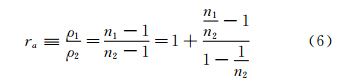
Considering Equation (3) and (6),the reciprocal of density can be expressed as follows:
where α1 and α2 are measured by the laser beam tracking system. A container connecting to Pitot tube collects the gas past the shock. A gas density meter (for example,the Sarasota ID900) set up in the container measures the gas density,ρ2. Hence,the refractive index,n2,is obtained using the Gladstone-Dale formula (Equation (5)). It is noted that the Pitot pressure measurement and the gas collection must be operated separately. The density ratio r and the inflow density ρ1 are obtained from Equation (7).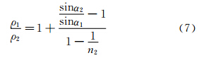
The accuracy of r measurement is based on the fact that the normal shock wave in front of the Pitot tube is so thin that the normal shock wave can be considered as a zero-thickness interface between two fluids with different densities[8]. Since the thickness of the shock wave is on the order of the magnitude of 10-4 mm[13],this consideration is rational for conventional hypersonic wind tunnels except for low-density wind tunnels.
We take the apparatus in CAAA for example to examine the feasibility of the measurement system. The two CCD cameras of MegaPlusII ES4020 (Redlake Company) with the resolution of 2048×2048 pixels (4.19Mpixel,integration time: 104μs) are supposed to be applied to record the refracted laser beam and the normal shock wave. The schematic graph for the camera recording system is shown in Figure 2. The field of view for each camera is 15mm×15mm and the spatial resolution for each pixel is 7.3μm. Considering the width of the laser beam is 50~200μm,the uncertainty for the recorded laser beam is below 15μm. The mobile spatial coordinate measuring system (MScMS) works to locate the two cameras with the position uncertainty of 2μm[14,15]. Thus the system uncertainty for measuring the position of the laser beam is limited within ±20μm. Taking the FD-3 hypersonic wind tunnel in CAAA for example,the test section for the experiment of the compressible mixing layer is 300mm(width) × 40mm(height) × 70mm(depth) [16].
 |
| 图 2 激光光束跟踪系统示意图。虚线代表支撑CCD相机(Camera-1和-2)的坐标系统。Camera-1位于MScMS系统的(x1,y1),记录折射激光位置;Camera-2位于MScMS系统的(x2,y2),记录正激波光线发生折射位置 Fig. 2 The schematic graph for the laser beam tracking system. The dash line indicates the coordinate system supporting CCD cameras,Camera-1 and Camera-2. Camera-1 is located at (x1,y1) in the coordinate system of MScMS to capture the image of the refracted laser beam. Camera-2 is placed at (x2,y2) in the coordinate system of MScMS to record the position where the laser beam is refracted by the normal shock wave |
Thus the distance between the two cameras is supposed to be 150mm,the uncertainty of the measured angle by Camera-1 is lower than 1.5×10⁻⁴ in radian number,and the corresponding relative error is under 0.01%.
With primary analysis of the relation between the Mach number and the density ratio as well as the pressure ratio,we found that the measurement is effective at 4<M1<8 and 1.1<γ<1.4. The specific heat ratio is relatively distinct in these ranges while the angle of refraction is sensitive to the density change. High accuracy of the specific heat ratio measurement can therefore be easily obtained under these test conditions. 3 Uncertainty analysis of measurement of specific heat ratio
Regarding the measurement of r = 1/ra=ρ2/ρ1 as shown in Equation (7),one can see that though r is determined by both α1 and α2. When α2 approaches 0° (or 90°),α1 is also close to 0° or (90°),and sin α2/sinα1 would bring large uncertainty to Equation (7). The analysis of the angle of refraction under the typical flow conditions (4<M1<8) suggests that 2°~10° would give relatively accurate α1.
According to Equation (2),the variance of r with different Mach numbers and specific heat ratios can be calculated,as shown in Figure 3 and Figure 4. Figure 3 shows the profiles of the density ratio,r,vs. the Mach number,M1. Note that r increases with the increase of M1. This trend is enforced by decreasing γ. Figure 4 is the profiles of r vs. γ at various M1. It is shown that,at higher Mach number,r is more sensitive to γ.
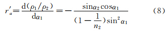
The error propagation for density ratio is analyzed here. From Equation (6),we have
 |
| 图 3 密度比与马赫数的关系Fig. 3 Density ratio,r, vs. Mach number,M1 |
 |
| 图 4 密度比与γ 的关系Fig. 4 Density ratio,r,vs. γ |

Considering the relative error of about 0.01% of Camera-1 obtained in the previous section,the relative error of the density ratio is about 0.5% based on the error relation,Equation (9). The accuracy of the density-ratio-measuring system is satisfactory.
From Equation (2),we have
and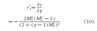

For estimating the uncertainty brought from the uncertainty in measuring r and M1,the relative error for the specific heat ratio γ is derived as follows,
where δγ/γ and δM1/M1 are the relative errors of the density ratio r and that of the Mach number M1,respectively. Estimation of the relative error of γ is obtained from Equation (12) with Equation (2),(10) and (11). If the uncertainty of r and M1 are supposed to be δr/r~δM1/M1~0.5% in the range of 4<M1<8 and 1.1<γ<1.4,δγ/γ is always less than 0.4%. Hence,the present method may provide an acceptable accuracy.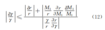
Let us analyze the error induced by the perfect gas assumption. Zebbiche (2011) reported that the error by using perfect gas relations is lower than 5% if the stagnation temperature T0 is lower than 1000K for any value of Mach number,and T0 may reach up to 3000K when Mach number is lower than 2.0[17]. Hence the present technique using the prefect gas model is effective to estimate γ in the hypersonic flow of T0<1000K. The gas at high temperatures becomes calorically imperfect gas; both Cp and γ vary with temperature. In order to measure γ for high temperature hypersonic flow,one has to introduce a nonlinear implicit equation for T and M1 and this takes more time for calculation and for data processing. By using the calorically imperfect gas model,for example the High Temperature model[17],the present measurement system is readily applicable for high temperature flows. 4 Discussion
The core of the technique is the measurement of the density ratio,r,which needs to be validated and verified at first. From Equation (1) and (2),one can see that if the ratio of the specific heat is predefined the two equations become two redundant functions for Mach number. The Mach number can be solved with the measured pressure ratio by Equation (1),and it also can be obtained with the measured density ratio by Equation (2). This provides a way of calibrating the density ratio measurement system. The calibration procedure may be summarized as follows: (a) obtain the Mach number at the point of interest by probing the pressures before and after the normal shock wave (see Equation (1)); (b) then calculate the Mach number with the density ratio derived from the angle of fraction of the laser beam (see Equation (2) and (7)); (c) finally validate and calibrate the density measurement system by comparing of the two Mach numbers.
In comparison with the gas chromatography technique,the present method may provide real time measuring results. The uniqueness of the present technique is the ability to obtain the Mach number and the density ratio of a hypersonic flow at the same time with a physically realizable system. With this measurement system the specific heat ratio of gases over the whole flow field can be obtained. In addition,the post processing of these results is more efficient and more extensive than that of gas chromatography,i.e. both spatial and temporal signals can be obtained. This technique is expected to have a wide range of applications in high speed flow measurements,though a few technical issues are yet to be addressed. For example,the structure and the size of the tube,the light path design,the combination of the tube and the laser beam,the thermal protection issues,the effects of the light source and the accurate record of the angle of refraction should be considered.
Several critical techniques in the measurement system are discussed here. First,since the laser beam emerging from the light source in Pitot tube passes through the stagnation and the post-shock regions,the gradient of the density will deflect the beam. The deflection angle can be obtained by measuring the displacement of the laser beam at the presence of the shock wave and simulating the geometrical optics in compressible flows. Secondly,the quality of the laser beam is a crucial factor for obtaining accurate refractive angle of the laser beam. The properties of light such as its reflection,dispersion,and refractive indices are determined by the media,i.e. the combustion gases in the present case. Hence,the frequency and the energy power of the laser beam should be well designed ahead. Thirdly,the physical structure of the Pitot tube should be designed as small as possible to attain the high spatial resolution,but it should still be able to generate a regular normal-shock-wave——an essential flow region making an ideal refraction of the laser beam. Finally,thermal protection of the tube is also a challenge to measurements in high temperature flows. At present this technique is under development in the laboratory. 5 Conclusion
(1) A novel,accurate and simple γ-measuring technique utilizing laser beam tracking and pressure measurement techniques has been presented. The key benefit of the new technique is the elimination of the complicated gas chromatography system.
(2) The pressures before and after the normal shock wave formed by Pitot tube are measured concurrently with the density ratio by laser beam tracking system. This improves the ease of use and reduces the time to obtain the final data for calibration of a hypersonic wind tunnel nozzle.
(3) Uncertainty estimation is illustrated with the examples of the available apparatus. The uncertainties of the technique are acceptable——the upper bound of the uncertainty is assured below 5.5% for any Mach number with T0<1000K.
(4) Feasibility analysis shows that the technique is physically realizable with several technical issues to be addressed. The present technique can be applied for other purposes,such as the realtime measurement of hypersonic flows.
| [1] | Felderman E J, Akers D T, Liu C T, et al. Hypersonic wind tunnel nozzle survivability for T&E final report: T&E/S&T project[R]. AEDC-TR-06-17, 2006 |
| [2] | Liu G. Principle of liquid rocket engines (in Chinese)[M]. Space Publishing Company, 1993. |
| [3] | Huebner L D, Rock K E, Voland R T, et al. Calibration of the Langley 8-foot high temperature tunnel for hypersonic airbreathing propulsion testing[R]. AIAA 96-2197, 1996. |
| [4] | Amirav A, Gordin A, Tzanani N. Supersonic gas chromatography/mass spectrometry[J]. Rapid Commun. Mass Spectrom, 2001, 15: 811-820. |
| [5] | Roseberry C M. Arc-heated gas flow experiments for hypersonic propulsion[D]. University of Texas, 2005. |
| [6] | Balachandran P. Fundamentals of compressible fluid dynamics[M]. Prentice-Hall of India Pvt. Limited, 2006. |
| [7] | Ames research staff. Equations, tables, and charts for compressible flow, Tech rep[R]. NACA-TR-1135, 1953. |
| [8] | Tropea C, Yarin A L, Foss J F. Springer handbook of experimental fluid mechanics[M]. Springer-Verlag, 2007: 216-228. |
| [9] | Matsuo K, Yaga M, Mochizuki H. Stability of normal shock waves in diffusers[J]. AIAA Journal, 1987, 25: 1515-1517. |
| [10] | Klein M V. Optics[M]. New York: Wiley, 1970. |
| [11] | Driscoll W G. Handbook of optics[M]. New York: McGraw-Hill, 1978. |
| [12] | Tropea C, Yarin A L, Foss J F. Springer handbook of experimental fluid mechanics[M]. Springer-Verlag, 2007: 473-474. |
| [13] | Anderson J D J. Fundamental of aerodynamics[M]. New York: McGraw-Hill Company, 1984. |
| [14] | Franceschini F, Galetto M, Maisano D, et al. Mobile spatial coordinate measuring system (MScMS)——introduction to the system[J]. Int J Prod Res, 2009, 47: 3867-3889. |
| [15] | Franceschini F, Maisano D, Mastrogiacomo L. Mobile spatial coordinate measuring system (MScMS) and CMMs: A structured comparison[J]. Int J Adv Manuf Technol, 2009, 42:1089-1102. |
| [16] | Wang T J, Shi X T, Chen J, et al. Multiscale structures in compressible turbulent mixing layers[J]. Mod Phys Lett B, 2010, 24:1429-1432. |
| [17] | Zebbiche T. Thermodynamics-interaction studies-solids, liquids and gases[C]. November, 2011, Ch. Effect of Stagnation Temperature on Supersonic Flow Parameters with Application for Air in Nozzles Zebbicc, 2011, 16: 421-444. |