


0 Introduction
The in-flight refueling technology has been widely used in long-range air strike/transportation and long-hour reconnaissance operation. The hose-drogue system will remain as an important technique approach in the future aerial refueling engineering. However,some challenges in designing and analyzing this aerial towed system still exist nowadays.
The hose-drogue assembly,when it has been released,is towed at the centerline of the afterbody or the wing-mount pod of the tanker. It mainly consists of a long flexible hose with circular section and a drogue attached to the free end of the hose. This structure is designed to maintain a steady configuration for coupling under the gravity,aerodynamic drag/lift force and the constraint force. However,the hose-drogue could orbit around the stable state because of the wake field turbulence or other unsteady flows. It may also move away from the original position when a receiver aircraft is approaching. The dynamic behavior of the hose-drogue system in unsteady flow field needs to be investigated effectively for detailed engineering application.
This paper aims to present a more accurate time-variant method combining the multiple body dynamics (MBD) and the Computational Fluid Dynamics (CFD) to solve the aerial towed problems. Multi-rigidbody theory and the finite element method are used in used in modeling the constrained hose and drogue structure. Overset structured composite grids are applied to adapt the moving body geometries. Component grids are meshed around the drogue and the receiver aircraft. A 3-D parallel RANS solver PMB3D is used to solve each CFD time step on the updated grids.
The theory,algorithm and modules of the multibody solver are presented. The cable elements based on the absolute nodal coordinate formula for the hose modeling is introduced. The dynamic response of a hose-drogue refueling assembly with a receiver aircraft approaching is obtained. The influence of approaching parameters (velocity profiles/initial offset of the receiver) on the drogue’s motion are investigated to optimize the probe-drogue coupling.
 |
| Fig. 1 F-35 fighters refueled from KC- 130. |
The study of the dynamics of an aerial cable towed system has a long history. Early work by Glauert [1] in the 1930s mainly concentrated on the stability of the towed body and neglected the cable’s physical properties. For the next several decades,people began to use rigorous analytic equations to examine the cables in the towing system [2, 3, 4, 5] and obtained a series of design principles and conclusions based on the classic cable theory. However,these partial differential equations are usually problem specified and need certain mathematic skills to solve. Furthermore,the cable theory is developed for high-tension strings and can not deal with the cable with compression,bending and torsion properly. The aerial refueling hose has a typical low tension as the towing cables and needs a different modeling approach.
Zhu & Meguid [6] gave a nice review about the aerial towed cable modeling technique,they concluded that the approaches based on the beam theory are most appealing. Meanwhile,the classic beam theory uses the nodal incremental displacements on the curvilinear coordinates as the unknown variables,which leads to complicated nonlinear parts in inertia terms of the equations of motion.
The Absolute Nodal Coordinate Formulation (ANCF) is first proposed by Shabana [7] and is designed to solve the flexible multibody problems with large displacement and large deformation. The ANCF uses the global coordinates and the finite slopes of the element nodes as the generalized variables,which can neglect the infinitesimal slope restriction in the ordinary FEM. The ANCF has been intensively studied and developed by the researchers in the recent years to apply it for varies kinds of engineer structures as beams,plates,membranes and solids,and its efficiency and accuracy has been proven [8]. In this paper,a certain kind of cable/beam element is needed to discrete the long refueling hose,which has the characteristics listed below:
1) The hose has a large length-diameter ratio and a circular section,and is made up of isotropic material;
2) The section plane of the hose is rigid,which means it stays perpendicular to the axis before and after the hose’s deformation according to the Euler-Bernoulli beam assumption;
3) The kinetic energy and the elastic energy of the torsion of the hose section are neglectable considering the large length-diameter ratio and engineering experience.
Considering these structure features,a 12-d.o.f three dimensional thin beam element shown in Fig. 2. is chosen. The two end points are defined as element nodes. In each node,the absolute nodal coordinate vector ri and the slope vector ri' are set as its generalized coordinates ei,which are the unknown kinetic variables to be solved.
 |
| Fig. 2 2-node ANCF cable/thin beam element. |
The dynamic equations of the thin beam element is obtained using the Second Lagrange Equations,which has a standard form:
where the kinetic energy T,strain energy U and the virtual work of external forces δW are defined as: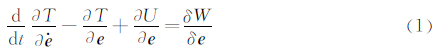
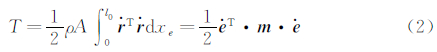
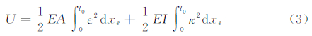
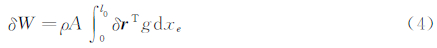
By substituting Eqs.(2)-(4) into Eq. (1),the structure dynamics (SD) equations of the i th element is obtained.
The mass matrix,elastic force and external force of the elastic system are assembled by N elementary ones directly based on the FEM framework. The mass matrix can be written with a chain of elements for the cable.
We have the dynamics equations of the flexible multibody based on the ANCF regardless of constraints,where e is the generalized coordinate vector of the flexible parts of the system.
1.1.2 Constraints and System Solving Equations
In the modeling of the multibody system,the configuration of the system is identified by a set of Cartesian-based generalized coordinates q [9],which describe the locations and orientations of the bodies. The ideal constraints between rigid or elastic parts can always be written in a series of algebraic constraint equations as:

In refueling drogue-hose modeling,two types of constraints are mainly considered. One is the joint between a fixed point and the cable’s root node,the other is the joint between the cable’s tip node and the rigid drogue.
Written in a general matrix form,the dynamic system equations which combines the multiple rigidbody dynamics and the FEM based on ANCF are
where qr are the rigidbody generalized coordinate vector. Qr includes the inertia force and external force of the rigidbody. Qe includes the elastic forces and external forces of the flexible parts. Eq.(6) and Eq. (7) are composed of the Differential Algebraic Equations (DAEs) of the dynamic system,with the generalized coordinates and the Lagrange multiplier as the unknown variables.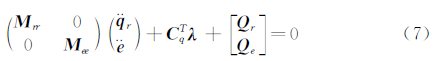
The Backward Differentiation Formulation (BDF) integration technique is used to transform the DAEs into the nonlinear algebraic equations,the latter can be solved by the Newton-Raphson iteration method.
1.2 MBS /CFD Solver: Algorithm & ValidationA coupled solver combining the multi-body system (MBS) dynamics and the CFD method has been developed.
The first step of the analysis is to initialize the multibody system and the flow field computation. The former gives the control parameters and the structure information of the dynamic system,while the latter needs three parts for CFD:
1) Mesh files and boundary information files.
2) Control parameters on overlapped grid and CFD technique.
3) Steady flow field files for initializing the unsteady calculation.
Three major steps are listed in the coupling strategy flowchart shown in Figure 3. The unsteady flow field is solved with the in house code PMB3D with URANS based on k -ω SST model.
 |
| Fig. 3 MBD/CFD coupling algorithm. |
The approaching and coupling process between the receiver aircraft and the tanker’s hose-drogue assembly is the crucial step in aerial refueling dynamics. The drogue will swing outward away from the forebody of the receiver when it moves along the route from the probe’s tip to the center of drogue straight forwardly. A numerical simulation of the approaching process is needed to investigate the aerodynamic interaction phenomenon.
2.1 Model & ParametersThe refueling coupling system,which is shown in Figure 4,includes a receiver aircraft and a hose-drogue assembly. The tanker is temporarily absent because this article focuses on the two-body interaction between the receiver and drogue,the effect of the tanker’s wake field shall be considered for the future work.
 |
| Fig. 4 Refueling coupling system: receiver aircraft and hose- drogue. |
The parameters of the refueling system,which are based on the hose-drogue structure of KC-10 tanker [11] ,are listed in Table 1. The refueling hose is modeled with a chain of one dimensional ANCF beam elements described in section 1.1. The tip node is constraint to a fixed point in space with the SGN joint (sphere joint between ground and cable node),while the end node is constraint to the drogue with the CBN joint (clamped joint between ground and cable node).
| Hose | ||||
| Total Length (Initial) /m | Inner Diameter /cm | Outer Diameter /cm | Young's Modular E/GPa | Mass per Length /(kg·m-1) |
| 22.86 | 5.08 | 5.30 | 50.0 | 2.381 (Dry) 4.093 (Wet) |
| Drogue | ||||
| Mass /kg | Bottom Radius/m | Mass Moment of Inertia/(kg·m2) | ||
| Ixx | Iyy | Iyy | ||
| 29.484 | 0.408 | 2.393 | 2.149 | 2.149 |
The receiver aircraft is an advanced fighter with an refueling probe attached to the right side of the body. Deflexed slats are deployed to maintain a larger lift coefficient in a comparatively low speed while coupling. The tip of the refueling probe has a offset distance Z0=1.62m and Y0=1.51m from the center line of the plane.
The PMB3D solver provides a powerful multi-zonal overlapped grid approach to handle the complex geometries and multibody system.
The aerial refueling approaching simulation is divided into three steps:
1) Steady flow field. Calculate the steady flow field of the system in its initial configuration.
2) Equilibrium state. Obtain the static configuration of the hose and drogue with the presence of the receiver at the starting position by running a time-accurate simulation.
3) Approaching process. A continuation of the Equilibrium state step simulation is conducted as the receiver moves towards the hose-drogue assembly and the dynamic corresponding of refueling system is obtained.
2.2 Approaching Parameters: VelocitiesFrom the starting position to the prescribed coupling point,the receiver aircraft shall move forward by a distance of L0=6.0m. The time-velocity profile for the approaching process,which is generally controlled by the pilot,may have effect on the dynamic response of the drogue-hose assembly.
The parameters for the steady flow solution are listed in Table 2. The angle of attack and yawing are 0°. The grid has a total mesh amount of 11.8 million . The parallel calculation is performed by 32 processes with the High Performance Computer (HPC) owned by Computational Aerodynamics Institute (CAI) of CARDC. A multigrid method has been applied to accelerate the converging process.
| Ma | Altitude/m | Density/(kg·m-3) | Viscosity/(N·s·m-2) | Re |
| 0.63 | 7620 | 0.546 3 | 1.539×10⁻⁵ | 1.112 8×10⁸ |
The receiver aircraft is driven directly to the drogue with a given closure velocity profile. Each of the velocity profile first performs as a linear increase of approaching speed and then stays at the maximum value of 0.5,1.0,2.0,3.0m/s. The overall distance L0 keeps a constant value for all four velocity profile.
As the receiver approaches,the drogue gradually swings outward from its original position for all the closure profiles given above. The wall compression effect of the aircraft’s forebody keeps pushing the drogue away from its original steady state. This phenomenon is consistent with the results from Vassberg [11].
2.3 Approaching Parameters: Initial OffsetsAs stated above,the approaching receiver creates a induced motion for the drogue,which drives it both upward and outward from its starting position and misses the coupling with the refueling probe. An apparent thought is to adjust the initial position of the receiver in the y-z plane to compensate for the drogue’s induced motion. The drogue is moved in the opposite direction of the induced offsets (-y and +z direction).
A computation table including 3×3 points is listed in Table 3,where 3 offset distances on the y direction and 3 offset distances on the z direction for the drogue-hose are set. The overall nine cases shall be simulated for the approaching process to investigate the induced motion. The relative position between the probe tip and the mass center of the drogue is checked for the nearest case as the best coupling offset.
| Δz/m | Δy/m | ||
| 0.0 | -0.35 | -0.70 | |
| 0.0 | y0-z0 | y1-z0 | y2-z0 |
| 0.45 | y0-z1 | y1-z1 | y2-z1 |
| 0.90 | y0-z2 | y1-z2 | y2-z2 |
The closure profiles for all cases of this section is based on the Vmax=0.5m/s velocity profile in section 2.2. The steady flow field solving,equilibrium state computation and approaching simulation are performed successively for all nine cases.
After the receiver finishes its closure route,the y-z positions of the refueling probe tip and the mass center of the drogue for each offset case are demonstrated in Fig. 5. The “P” point represents probe while “D” stands for drogue. The suffix “-01”,for example,means the y0-z1 case. It can be seen that for the refueling system here,the y1-z2 offset case results in a minimum coupling distance between drogue center and probe tip,for which Δr=0.192m.
 |
| Fig. 5 Positions for the probe tip (P-xy) and drogue mass center (D-xy) at the end of the approach (Vmax=0.5m/s). |
A MBD/CFD coupling method for the numerical simulation of the aerial towed system is developed. By simulating the aerial refueling approaching process of an advanced fighter,the system structure dynamics and aerodynamic characteristics are obtained. Approach parameters including various speeds and offset distances,are considered. Future work may include the tanker wake field effect and the study of hose tension control by a reel-drum during coupling process. Pre-contact motion of the hose-drogue shall be analyzed and the risk of the oscillation in coupling process needs to be evaluated.
| [1] | Glauert M. The stability of a body towed by a light wire[R]. London:Aeronautical Research Council, T R 1312, 1930. |
| [2] | Schram J, Reyle S. A three-dimensional dynamic analysis of a towed system[J]. Journal of Hydronautics, 1968, 2(4):213-220. |
| [3] | Simonenko, Alexander. Influence of extensibility on tension in a towed cable[J]. Journal of Hydronautics, 1975, 10(1):26-28. |
| [4] | Mattis G De. Longitudinal dynamics of a towed sailplane[J]. Journal of Guidance, Control and Dynamics, 1993, 16(5):822-829. |
| [5] | Nakagawa N, Obataf A. Longitudinal stability analysis of aerial-towed systems[J]. Journal of Aircraft, 1992, 29(6):978-985. |
| [6] | Zhu Z H, Meguid S A. Elastodynamic analysis of aerial refueling hose using curved beam element[J]. AIAA Journal, 2006, 44(6):1317-1324. |
| [7] | Shabana, Ahmed A. An absolute nodal coordinate formulation for the large rotation and deformation analysis of flexible bodies[R]. MBS96-1-UIC, Department of Mech. Eng., University of Illinois at Chicago, 1996. |
| [8] | Yoo W S, Dmitrochenko O, Pogorelov D Y. Review of finite elements using absolute nodal coordinates for large-deformation problems and matching physical experiments[C]//The ASME 2005 International Design Engineering Technical Conferences & Computers and Information in Engineering Conference, Long Beach, California USA, 2005. |
| [9] | Shabana A A. Dynamics of multibody systems[M]. UK:Cambridge University Press, 2005. |
| [10] | Vassberg J C, Yeh D T, Blair A J, et al. Numerical simulations of KC-10 wing-mount aerial refueling hose-drogue dynamics with a reel take-up system[C]//The 21st Applied Aero-dynamics Conference. Orlando, Florida, 2003. |
| [11] | Vassberg J C, Yeh D T, Blair A J, et al. Numerical simulations of KC-10 in-flight refueling hose-drogue dynamics with an approaching F/A-18D receiver aircraft[C]//The 23rd AIAA Applied Aerodynamics Conference. Toronto, Ontario Canada, 2005. |