


2. 中国空气动力研究与发展中心 计算空气动力研究所,四川 绵阳 621000
2. Computational Aerodynamics Institute of China Aerodynamics Research and Development Center, Mianyang 621000, China
Leading the development direction and the latest technology of hypersonic vehicles,the past and present vehicle configurations proposed by the U.S. should be concerned greatly. Three hypersonic vehicles (X-37[1, 2],X-51A[3] and HTV-2[4, 5]) of extreme importance were flight tested in the year of 2010,aiming at individual vehicle mission and aerodynamic characteristics validation,i.e.,orbital maneuvering,reusable capability,hypersonic scramjet and aerodynamic gliding.
In the process of hypersonic reentry,hypersonic aerodynamics,aerothermodynamics and flight mission design are the main test items. The hypersonic aerodynamic characteristics are determined by the vehicle configuration,and the capability of completing the flight missions is determined by the design of flight trajectory.
In this paper,the parametric geometrical configurations are proposed via conic cross section design method and the “class function and shape function transformation technique” (CST),and then the aerodynamic characteristics are predicted by a rapid and effective engineering method. The configuration is optimized to satisfy both design goals of maximum lift-to-drag ratio maximum volume utility ratio simultaneously. The optimization of flight trajectory design considering the integration of aerodynamics and aerothermodynamics is investigated based on a given configuration. 1 Parametric geometrical configuration
Parametric geometry representation is the foundation of optimization of hypersonic vehicle configuration,and its goal is to describe a wide set of vehicle configurations with a limited set of variables. In this paper,the conic cross section design method and the “class function and shape function transformation technique” (CST) are used to describe the aerodynamic configuration.
In the conic cross section design method,in order to describe a conic whose start point and end point are given,five independent conditions should be known. Commonly,the five conditions are the coordinates and the slopes of start point and end point,and the conic shape parameter. Various conic cross sections can be constructed rapidly,conveniently,accurately and respectively according to the various requirements of the vehicle designer[6].
The “class function and shape function transformation technique” (CST) can describe a wide variety of body cross section shapes by varying the exponents of the class function. The very general cross-section shapes can be generated by varying the shape function formulations in addition to the class functions[7, 8].
A variety of configurations of hypersonic vehicles are proposed by using the two methods described previously. The configurations are shown in Fig. 1.
 |
| Fig. 1 Parametric geometrical configurations 图 1 参数化外形 |
There are two kinds of optimization which are called single-objective optimization and multi-objective optimization. For hypersonic vehicle optimization of configuration and trajectory,the multi-objective optimization is usually used instead of the traditional single-objective optimization. In this paper,the multi-objective optimization problem is solved by using the method of weighting.
Different objectives have different orders of magnitude,in order to have comparability between them,the values of the objectives are divided by the initial value of themselves respectively. Hence,the objective function is described as below:
where J is the objective of optimization; ω1 and ω2 are the weighting factors; F1 and F2 are the values of objective 1 and 2; (F1)0 and (F2)0 are the initial values of objective 1 and 2 respectively.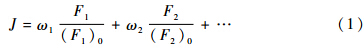
The method described here can be used in the multi-objective optimization of configuration and trajectory for hypersonic vehicles,and the detailed description will be shown in part 4 and part 5. 3 Optimization of configuration
The hypersonic aerodynamic characteristics of hypersonic vehicles are determined by the vehicle configuration. For a given configuration,the hypersonic aerodynamic characteristics are predicted by the rapid and effective engineering method[9, 10, 11, 12, 13]. Different methods are selected according to the different configurations of vehicle components. The Embedded Newtonian theory is used for the fuselage and Dahlem Buck Empirical method is used for the other components. The Prandtl-meyer expansion method is used for the leeward modification. These methods have been applied in large number of hypersonic aerodynamic investigations and verified by some wind tunnel experiments and CFD results. The accuracy of these methods is acceptable in the stage of conceptual design.
The parametric geometrical configurations are generated with a limited set of variables. Different values of the variables correspond different configurations,and then lead to different aerodynamic characteristics. The purpose of the configuration optimization is to find the proper values of variables which lead to the optimal aerodynamic characteristics.
In this part,the configuration optimization of HTV-2 analog vehicle is investigated as an example to illustrate the optimization of configuration.
For HTV-2 analog vehicle shown in Fig. 1,the two objectives are selected to be the maximum lift-to-drag ratio and the maximum volume utility ratio. Hence the objective function is:
where CL/CD is the lift-to-drag ratio,VS is the volume utility ratio,and the subscript 0 means the initial value.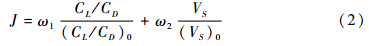
As shown in Fig. 2,the five design variables are H,HL/H,x,and the two angles θ1 and θ2. The constraint of the design variables is θ1≥θ2. In order to analyse the variables with different orders of magnitude and units,the variables are transformed to make sure that the ranges of them are [0,1]. The initial values of the five design variables are H0=0.3,(HL/H)0=0,x0= 0.67,(θ1)0=0.5 and (θ2)0=0. The mach number of this example is 7.0,and the angle of attack is 10.0°.
 |
| Fig. 2 Design variables 图 2 设计变量 |
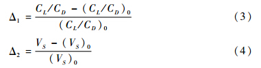
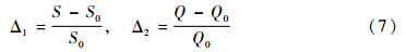
In order to show the effectiveness of the optimization,Table 1 shows the values of design variables,the lift-to-drag ratio and the volume utility ratio of the optimal configurations with different weighting factors,the increase or decrease to the initial values (Δ1and Δ2) are also shown in it. The definitions of them are:
As shown in Table 1,the configuration that maximizes the lift-to-drag ratio conversely has the minimum volume utility ratio,and the one that maximizes the volume utility ratio has the minimum lift-to-drag ratio. The intermediate solutions have averaged values. The bottom cross sections of the optimal configuration with different weighting factors are shown in Fig. 3. There are obvious differences between the bottom cross sections,which one would be chosen depends on the designer’s requirements.
| ω1 | ω2 | H | HL / H | X | θ1 | θ2 | CL/CD | Δ1 | VS | Δ2 |
| Initial | 0.3 | 0.0 | 0.67 | 0.5 | 0.0 | 3.96 | - | 0.38 | - | |
| 1.0 | 0.0 | 0.0 | 0.0 | 0.0 | 0.0 | 0.0 | 4.50 | 13.6% | 0.34 | -10.5% |
| 0.65 | 0.35 | 0.26 | 0.0 | 0.0 | 0.0 | 0.0 | 4.19 | 5.8% | 0.40 | 5.3% |
| 0.4 | 0.6 | 1.0 | 1.0 | 0.0 | 0.0 | 0.0 | 2.41 | -39.1% | 0.68 | 78.9% |
| 0.0 | 1.0 | 1.0 | 1.0 | 0.25 | 0.0 | 0.5 | 2.17 | -45.2% | 0.69 | 81.6% |
 |
| Fig. 3 Bottom cross sections 图 3 底部截面形状 |
In the simulation of the reentry trajectory,the aero-dynamic data predicted by the engineering method is used. For a given configuration,if the initial conditions and the control strategy are given,the reentry trajectory can be obtained by using the three degrees-of-freedom (3-DoF) equations of motion. In the coordinate transformation,the quaternion is used instead of the Euler angle. Because the quaternion can avoid the problem of the Euler angle which could make the equation of motion singular in some special conditions.
The quaternion is defined as an expression that is the sum of a real number and a vector. It uses one angle and one space axis to describe a coordinate system rotation,but the Euler angle method uses three coordinate axes and three angles. The disadvantage of the quaternion is that it is not intuitional enough. By using the relationship between the quaternion and Euler angle,we can transform one to another easily. Thus,the quaternion is used in the coordinate transformation during the simulation of trajectory,and the Euler angle is used to output to make the result intuitional[14].
In order to solve the differential equations of motion,a fourth order Runge-Kutta scheme is used in the numerical integration. The rotation of the earth is considered in the simulation,and the earth ellipsoid model is used.
The task of the optimization of trajectory is to obtain the optimal control strategy which could lead to some optimal results that the designers want based on the given configuration and initial conditions.
In this part,the trajectory optimization of the X-37 analog transporter is investigated as an example to illustrate the optimization of trajectory.
For X-37 analog transporter shown in Fig. 1,the two objectives are the maximum range of the trajectory and the minimum total heat load of the stagnation point. Hence the objective function is:
where S is the range of the trajectory,Q is the total heat load of the stagnation point and the subscript 0 means the initial value.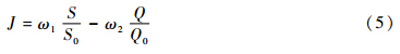
For X-37 analog transporter,the speed braking characteristic is very important. Huge amount of kinetic energy and potential energy must be consumed to make sure that the transporter can land on a conventional runway easily. Thus,the transporter must flight at a high angle of attack in the range of high altitude and a low angle of attack in the range of low altitude[15]. Hence,the control strategy can be described as:
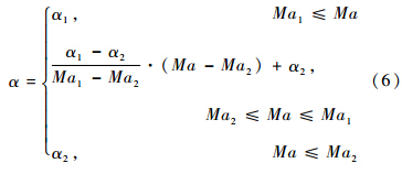
The design variables are the two mach numbers Ma1 and Ma2,and α1 and α2 are given in the calculation. The constraint of the two design variables is Ma1≥Ma2,and the other constraint conditions are q≤q0 and  ≤0,where q is the dynamic pressure and is the heat flux of the stagnation point,q0 and 0 are the maximum value of them and they are given in the calculation.
In order to analyse the variables with different orders of magnitude and units,the variables are transformed to make sure that the ranges of them are [0,-1]. The initial reentry altitude is 70km,and the flight path angle is -1°.
Table 2 shows the values of design variables,the range of the trajectory and the total heat load of the stagnation point of the optimal trajectories with different weighting factors,the increase or decrease to the initial values (Δ1 and Δ2) are also shown in it. The definitions of them are:
| ω1 | ω2 | Ma1 | Ma2 | S/m | Δ1 | Q/(kJ·m-2) | Δ2 |
| Initial | 0 | 0 | 3.0393×10⁶ | - | 1.1621×10⁶ | - | |
| 0.5 | 0.5 | 0.03 | 0.004 | 3.0716×10⁶ | 1.06% | 1.1675×10⁶ | 0.46% |
| 0.7 | 0.3 | 0.73 | 0.003 | 3.1799×10⁶ | 4.63% | 1.2374×10⁶ | 6.48% |
| 0.8 | 0.2 | 1.0 | 0.3 | 3.2792×10⁶ | 7.89% | 1.3219×10⁶ | 13.75% |
As shown in Table 2,the trajectory that maximizes the range have the maximum total heat load of the stagnation point,and the one that minimizes the total heat load of the stagnation point have the minimum range.The intermediate solutions have averaged values. The height,heat flux of the stagnation point and dynamic pressure along the optimal trajectories with different weighting factors are shown in Fig. 4~Fig. 6. There are obvious differences between each other,which trajectoy would be chosen depends on designer’s requirements.
 |
| Fig. 4 Height along the trajectory 图 4 高度-航程曲线 |
 |
| Fig. 5 Heat flux of stagnation point along the trajectory 图 5 驻点热流-航程曲线 |
 |
| Fig. 6 Dynamic pressure along the trajectory 图 6 动压-航程曲线 |
Parametric geometrical configurations are proposed via the conic cross section design method and the “class function and shape function transformation technique” (CST). The optimization of configuration and trajectory are analyzed based on the proposed analog configurations.
The aerodynamic characteristics used in the optimization are predicted by the rapid and effective engineering method,and the simulation of trajectory is calculated by using the three degrees-of-freedom (3-DoF) equations of motion. The rotation of the earth is considered,and the earth ellipsoid model is used in the simulation. The optimal configurations and trajectories with different weighting factors are obtained. There are obvious differences between the optimal results,which solution would be chosen depends on the designer’s requirements. The result can be used as one of the feasible schemes in the future work. Also,the moment characteristics and stability are very important in the research of hypersonic vehicles,and should be concerned greatly in the future work.
| [1] | CHAUDHARY A, NGUYEI V, IRAN H, et al. Dynamics and stability and control characteristics of the X-37[R]. AIAA-2001-4383, 2001. |
| [2] | WHITMORE S A, DUNBAR B J. Orbital space plane: past, present, and future[R]. AIAA 2003-2718, 2003. |
| [3] | HANK J M, MURPHY J S, MUTZMAN R C. The X-51A scramjet engine flight demonstration program[R]. AIAA 2008-2540, 2008. |
| [4] | WALKER S H, RODGERS F. Falcon hypersonic technology overview[R]. AIAA 2005-3253, 2005. |
| [5] | WALKER S H, SHERK Lt C J, et al. The DARPA/AF falcon program: the hypersonic technology vehicle #2 (HTV-2) flight demonstration phase[R]. AIAA 2008-2539, 2008. |
| [6] | TANG W, ZHANG Y, LI W J, et al. Aerodynamic design and optimization for vehicles with conic cross section[J]. Journal of Astronautics, 2004; 25(4): 429-433.(in Chinese). 唐伟, 张勇, 李为吉, 等. 二次曲线截面弹身的气动设计及优化[J]. 宇航学报, 2004, 25(4): 429-433. |
| [7] | KULFAN B M. A universal parametric geometry representation method-“CST”[R]. AIAA 2007-62, 2007. |
| [8] | FENG Y, TANG W, REN J X, et al. Parametric geometry representation method for hypersonic vehicle configuration[J]. ACTA Aerodynamica Sinica, 2012; 30(4): 546-550.(in Chinese). 冯毅, 唐伟, 任建勋, 等. 飞行器参数化几何建模方法研究[J]. 空气动力学学报, 2012, 30(4): 546-550. |
| [9] | HUANG Z C. Aerodynamics of hypersonic vehicle[M]. Beijing: National Defense Industry Press, 1995.(in Chinese). 黄志澄. 高超声速飞行器空气动力学[M]. 北京: 国防工业出版社, 1995. |
| [10] | TANG W, GUI Y W, FANG F. Aerodynamic configurations selection for lift reentry capsule[J]. Journal of Astronautics, 2008, 29(1):84-88.(in Chinese). 唐伟, 桂业伟, 方方. 新型升力再入飞船返回舱气动外形选型研究[J]. 宇航学报, 2008, 29(1): 84-88. |
| [11] | TANG W, FENG Y, NING Y, et al. Aerodynamics configuration conceptual design for X-38 analog lifting body transporter[J]. ACTA Aerodynamica Sinica, 2011, 29(5): 555-558. (in Chinese). 唐伟, 冯毅, 宁勇, 等. 类X-38 升力体运载器气动布局概念设计[J]. 空气动力学学报, 2011, 29(5): 555-558. |
| [12] | MOORE M, WILLIAMS J. Aerodynamic prediction rationale for analyses of hypersonic configurations[R]. AIAA 1989-0525, 1989. |
| [13] | ZHANG L M. Aerodynamicsanalysis of space shuttle[M]. Beijing: National Defense Industry Press, 2009.(in Chinese). 张鲁民. 航天飞机空气动力学分析[M]. 北京: 国防工业出版社, 2009. |
| [14] | YUAN Z H, QIAN X F. Control flight mechanics and computer simulation[M]. Beijing: National Defense Industry Press, 2001.(in Chinese). 袁子怀, 钱杏芳. 有控飞行力学与计算机仿真[M]. 北京: 国防工业出版社, 2001. |
| [15] | FENG Y, XIAO G M, TANG W, et al. Aerodynamics configuration conceptual design for X-37 analog transporter[J]. ACTA Aerodynamica Sinica, 2013, 31(1): 94-98.(in Chinese). 冯毅, 肖光明, 唐伟, 等. 类X-37运载器气动布局概念设计[J]. 空气动力学学报, 2013, 31(1): 94-98. |