2. 海洋石油工程股份有限公司 海洋工程技术中心, 天津 300451
2. Offshore Engineering Technology Center, Offshore Oil Engineering Co. Ltd., Tianjin 300451, China
海洋蕴含了世界70%的油气资源[1],海底管道是油气主要的输送手段。但是由于海洋环境的复杂多变,与陆地上相比海底管道铺设作业过程更加的复杂,对作业设备和工作人员具有更高的要求[2]。国内外学者对海底管道铺设的研究主要集中在对管道正常铺设[3-4]的管线形态和受力进行分析,对于初始铺设过程中的管道和缆索耦合系统的形态和受力在动态波浪和海流载荷下的研究较少。
初始铺管是通过初始缆牵引,将初始管道准确下放至海床预设区域内,初始管道放置的位置是否准确十分重要。马小燕[5]针对不同的工况和边界条件,对S型铺管的管线形态进行分段处理,采用不同的算法求解管线的上弯段、中间段和下弯段;杨立鹏等[6]针对管道柔性变形进行了研究;Yong Bai等[7]利用有限元法来求解管道形态。
本文以国内S型铺管实际施工作业案例为研究依据,基于非线性梁理论[8-9]对铺管过程进行计算,基于Euler-Bernoulli梁理论[10]建立了管道的初始铺设数学模型,采用微分求积法[11-12]确定方程组的边界条件,利用显式差分法[13]得到振动方程数值解,从而解算出管道和缆索的综合形态和受力。建立出一套实时求解的初始铺管仿真系统,进行海上初始管道铺设的工程预演[14],可极大程度的节省管道铺设工程的施工成本,减小施工周期,提高施工效率。
1 深水铺管视景仿真系统 1.1 硬件平台铺管仿真系统硬件由七部分组成:张紧器控制台、主控系统服务器、视景仿真服务器(四台)、网络交换机、DP控制台、教练员系统、立体投影设备。硬件结构如图 1所示。

|
Download:
|
| 图 1 铺管仿真系统硬件结构 Fig. 1 Pipelaying simulation hardware construction | |
视景仿真服务器与高性能视景显示器连接,负责数据处理和三维虚拟场景输出。DP控制系统提供铺管船输出控制信号,控制铺管船的定位和移船操作。主控系统服务器负责接收外部命令,以及数学模型的解算。张紧器控制台的操作信号主要是通过数据采集卡接收并转换。
仿真系统的硬件构成主要包括:五台主机,分别对应一台主服务器、两台视景服务器、一台甲板工位服务器、一台教练员服务器,12台显示器,分别对应软件操作界面、八台监控工位视景显示、一台甲板工位视景显示、教练员操作界面、教练员辅助操作界面,张紧器操作台,另外还包括第三方的DP控制台。
1.3 软件集成铺管模拟子系统主要包含四部分:铺管控制系统、张紧器操作台、铺管视景系统、DP操作台,其中,DP操作台是由第三方提供。张紧器操作台的软件模块主要是实现数据的采集、数据的信号转换、网络通信、绞车控制以及张紧器的软件操作界面。铺管软件构成如图 2所示。

|
Download:
|
| 图 2 铺管软件功能框图 Fig. 2 Pipelaying software functional diagram | |
铺管集成控制系统提供仿真系统的软件操作界面,该界面可以进行参数输入输出以及数据监测,数学模型的解算在该部分实现,而且铺管集成控制系统提供与其他子系统的软件接口,包括与DP操作台的软件接口、与张紧器操作台的软件接口、与视景仿真系统的软件接口。
铺管视景仿真系统主要包括视景驱动模块和视景模块,视景驱动模块通过调用Quest 3D软件提供的接口控件与视景模块进行数据交互。
管线铺设过程中,船体、张紧器、管线等的姿态需要实时运算与刷新,数据量庞大,本视景方案基于Quest 3D平台,通过自主开发的高速接口模块,完成海量数据的实时传输。
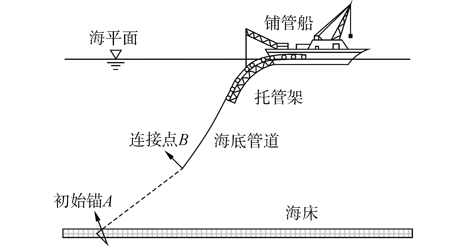
2 初始铺管数学模型 2.1 管道和缆索受力分析图 3所示为初始铺管的管线形态示意图,AB段的虚线为初始缆,缆索分别与初始锚和管线连接。由材料力学知识可知,在连接点B位置,起始缆与管道的张力大小相等,方向相反,且弯矩为0。在连接点处,缆索系统与管道系统,共用相同的张力以及位移参数。两个系统共同访问几个相同的变量和参数,这是属于基本的外部耦合,所以他们是一个耦合的系统。
|
Download:
|
| 图 3 初始铺管示意图 Fig. 3 Initial pipe laying schematic diagram | |
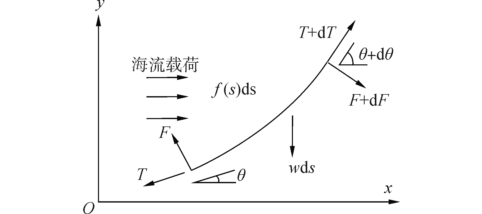
海底管道和缆索受到来自波浪载荷、海流载荷以及船体运动等多种因素的影响,得到精确的解析数学模型非常困难,为使问题简化,作出如下假设[15]:1)变形主要发生在竖直面内;2)管道在竖直方向受力均匀分布。对管道取一微段进行分析,在自然坐标系下建立管道微段的平衡微分方程[16]。微段受力如图 4所示。
|
Download:
|
| 图 4 管道微段受力分析 Fig. 4 Pipeline unit force analysis | |
图 4中,沿单元轴向的法线对力进行分解得到
| $ \left\{ \begin{array}{l} {\rm{d}}T/{\rm{d}}s = w\sin \theta - f\left( s \right)\cos \theta \\ {\rm{d}}F - T{\rm{d}}\theta + w\cos \theta {\rm{d}}s + f\left( s \right){\rm{d}}s = 0 \end{array} \right. $ | (1) |
式中:F为管道剪切力分量;f(s)为海流引起的外部载荷;θ为管道单元倾角;w为管道浮重度,单位长度管道在海水中的质量,kg/m。
将式(1)整理得
| $ EI\frac{{{{\rm{d}}^3}\theta }}{{{\rm{d}}{s^3}}} - T\frac{{{\rm{d}}\theta }}{{{\rm{d}}s}} + w\cos \theta + f\left( s \right) = 0 $ |
式中EI为管道弯曲刚度。
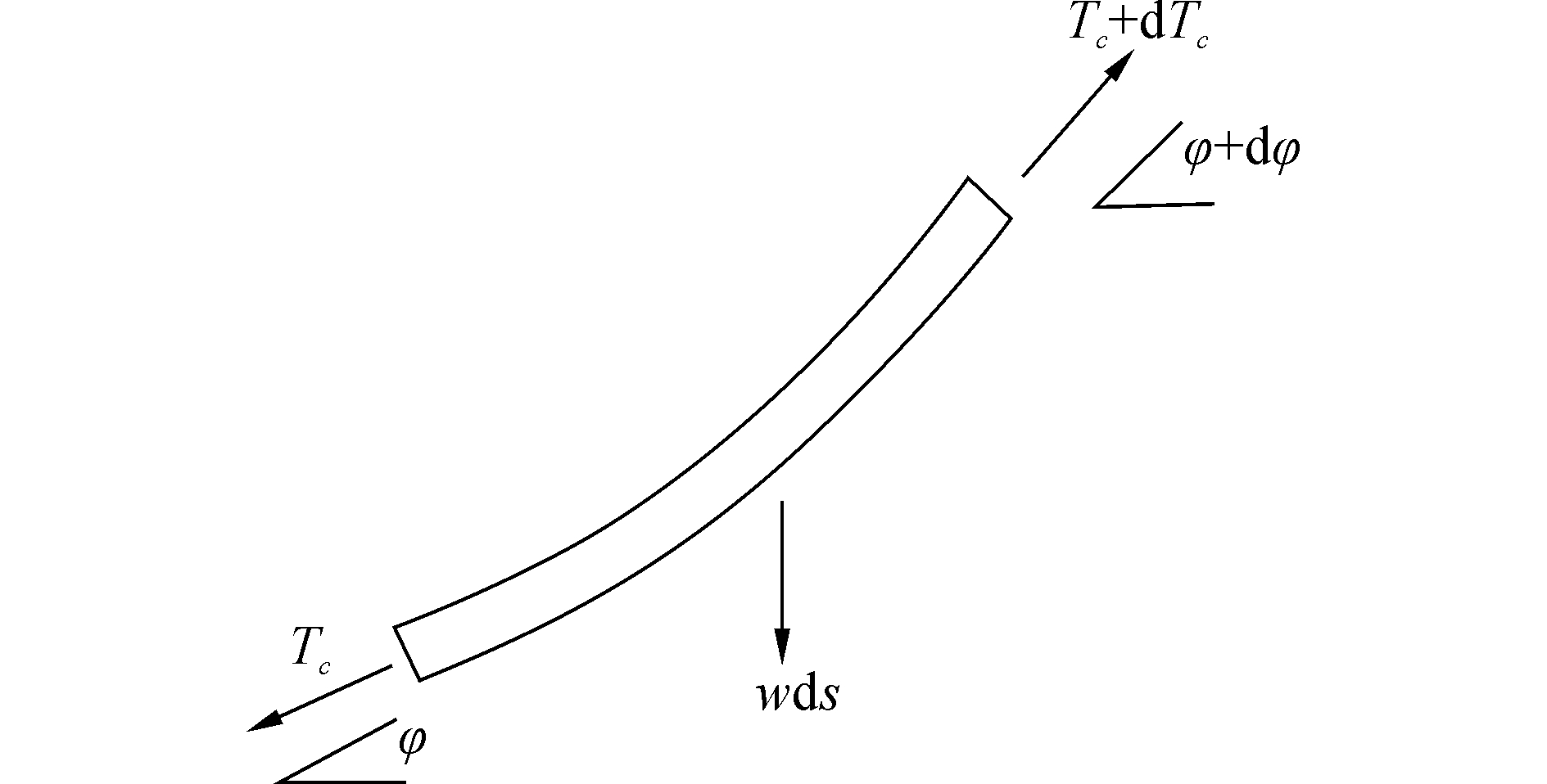
从初始缆中取任意微段单元,设微段长度为ds,两端受到的拉力分别为Tc和Tc+dTc,在起始缆自重的情况下,管道受到的轴向张力变大,且产生一定的转角dφ。微段受力如图 5所示。
|
Download:
|
| 图 5 初始缆微段受力分析 Fig. 5 Initial cable force analysis | |
忽略海流载荷对起始缆的影响[18],根据缆索单元轴向受力平衡,可以得到
| $ \left( {{T_c} + {\rm{d}}{T_c}} \right) = {w_c}{\rm{d}}s\sin \varphi + {T_c} $ | (2) |
将式(2)整理得到
| $ {\rm{d}}{T_c} = {w_c}{\rm{d}}s\sin \varphi $ |
忽略dTc的影响,根据缆索单元法向受力平衡可得
| $ {T_c}{\rm{d}}\varphi = {w_c}{\rm{d}}s\cos \varphi $ |
式中:wc为起始缆的浮重度,φ为缆索单元倾角。
缆索的浮重度wc可以根据下式计算得到
| $ {w_c} = \frac{{{\rm{ \mathsf{ π} }}D_c^2}}{4}g\left( {0.7{\rho _c} - {\rho _w}} \right) $ | (3) |
式中:Dc为缆索直径,m;ρc为缆索钢材密度,kg/m3;ρw为海水密度,kg/m3。
2.2 管道振动方程管道受到波浪载荷、船舶运动等影响,会产生振动。在分析管道、缆索系统的力平衡方程基础之上,利用叠加原理,将管道的振动特性,叠加到初始铺管的过程中。
设管道长度为l(t),管道铺设速度为V,轴向力为P,密度为c,管道截面为A,管道轴向变形与管道的横向位移y(x, t)比较可以忽略不计[20]。为便于分析,以管道脱离点为坐标原点O,管道轴线方向为x轴,法向方向为y轴建立坐标系,图 6是管道的振动分析图。

|
Download:
|
| 图 6 管道的振动分析 Fig. 6 Pipeline vibration analysis | |
在管道的横向振动过程中,管道铺设速度是匀速的,即
| $ \frac{{\partial x}}{{\partial t}} = V,\frac{{{\rm{d}}V}}{{{\rm{d}}t}} = 0 $ |
而管道的横向振动速度可以表示为
| $ \frac{{{\rm{d}}y\left( {x,t} \right)}}{{{\rm{d}}t}} = \frac{{\partial y}}{{\partial x}}\frac{{\partial x}}{{\partial t}} + \frac{{\partial y}}{{\partial t}} = V\frac{{\partial y}}{{\partial x}} + \frac{{\partial y}}{{\partial t}} $ |
管道总动能为
| $ W = \frac{1}{2}\rho Al{V^2} + \frac{1}{2}\rho A\int_0^l {{{\left( {V\frac{{\partial y}}{{\partial x}} + \frac{{\partial y}}{{\partial t}}} \right)}^2}{\rm{d}}x} $ | (4) |
管道的总势能为
| $ U = \int_0^l {\left[ {P\varepsilon + + \frac{1}{2}EI\left( {\frac{{{\partial ^2}y}}{{\partial {x^2}}}} \right)} \right]{\rm{d}}x} $ | (5) |
式中:
将式(4)进行变分得
| $ \delta W = \rho AV\int_0^l {\left( {V{y_x} + {y_t}} \right)\delta {y_x}{\rm{d}}x} + \rho A\int_0^l {\left( {V{y_x} + {y_t}} \right)\delta {y_t}{\rm{d}}x} $ |
根据哈密顿(Hamilton)原理[21],且忽略高阶项可得管道振动微分方程:
| $ EI\frac{{{\partial ^4}y}}{{\partial {x^4}}} + \rho A\frac{{{\partial ^2}y}}{{\partial {t^2}}} + 2\rho AV\frac{{{\partial ^2}y}}{{\partial x\partial t}} + \rho A{V^2}\frac{{{\partial ^2}y}}{{\partial {x^2}}} - P\frac{{{\partial ^2}y}}{{\partial {x^2}}} = 0 $ | (6) |
式(6)即是管道横向振动微分方程,
差分法[22]适用于所有水深,在深水铺管计算中,用差分法求解微分方程组可以免除对方程引入某些物理简化,计算效率高。采用显式差分法对初始铺管过程中管线振动方程(6)进行离散求解:
| $ \begin{array}{*{20}{c}} {y_j^{n + 1} = \frac{a}{{{a_3}}}y_{j + 2}^n + \frac{{{a_1}}}{{{a_3}}}y_{j + 1}^n + \frac{{{a_2}}}{{{a_3}}}y_j^n + \frac{{{a_4}}}{{{a_3}}}y_j^{n - 1} + }\\ {\frac{{{a_5}}}{{{a_3}}}y_{j - 1}^n + \frac{{{a_6}}}{{{a_3}}}y_{j - 2}^n + \frac{{{a_7}}}{{{a_3}}}y_{j + 1}^{n - 1} + \frac{{{a_8}}}{{{a_3}}}y_{j - 1}^{n - 1} + \frac{{q\left( {jh,n\tau } \right)}}{{{a_3}}}} \end{array} $ | (7) |
其中
| $ a = \frac{{EI}}{{{h^4}}},{a_1} = \frac{{ - 4EI}}{{{h^4}}} + \frac{{\rho AV}}{{h\tau }} + \frac{{\rho A{V^2} - P}}{{{h^2}}} $ |
| $ {a_2} = \frac{{6EI}}{{{h^4}}} - \frac{{2\rho A}}{{{\tau ^2}}} - \frac{{2\rho A{V^2} - 2P}}{{{h^2}}},{a_3} = - \frac{{\rho A}}{{{\tau ^2}}} $ |
| $ {a_4} = \frac{{\rho A}}{{{\tau ^2}}},{a_5} = \frac{{ - 4EI}}{{{h^4}}} - \frac{{\rho AV}}{{h\tau }} + \frac{{\rho A{V^2} - P}}{{{h^2}}} $ |
| $ {a_6} = \frac{{EI}}{{{h^4}}},{a_7} = - \frac{{\rho AV}}{{h\tau }},{a_8} = \frac{{\rho AV}}{{h\tau }} $ |
结合初始条件可以得到差分格式为
| $ y_j^0 = 0,y_j^1 = y_j^{ - 1} $ | (8) |
结合边界条件可以得到差分格式为
1) 当x=0时,
| $ \left\{ \begin{array}{l} y_0^n = {y_0}\left( {n\tau } \right)\\ y_1^n - y_{ - 1}^n = 2h{\theta _1} \end{array} \right. $ |
2) 当x=L时,
| $ y_{m + 1}^n - y_{m - 1}^n = 2h{\theta _n} $ |
| $ y_m^n = \frac{{y_{m + 1}^n - y_{m - 1}^n}}{2} $ |
| $ y_{m + 2}^n = \frac{{2EI + P{h^2}}}{{EI}}y_{m + 1}^n - \frac{{2EI + P{h^2}}}{{EI}}y_{m - 1}^n + y_{m - 2}^n $ |
对式(7)在初始计算时处理如下
| $ \begin{array}{*{20}{c}} {y_j^1 = \frac{a}{{{a_3}}}y_{j + 2}^0 + \frac{{{a_1}}}{{{a_3}}}y_{j + 1}^0 + \frac{{{a_2}}}{{{a_3}}}y_j^0 + \frac{{{a_4}}}{{{a_3}}}y_j^{ - 1} + }\\ {\frac{{{a_5}}}{{{a_3}}}y_{j - 1}^0 + \frac{{{a_6}}}{{{a_3}}}y_{j - 2}^0 + \frac{{{a_7}}}{{{a_3}}}y_{j + 1}^{ - 1} + \frac{{{a_8}}}{{{a_3}}}y_{j - 1}^{ - 1}} \end{array} $ |
结合初始条件可以得到
| $ y_j^1 = \frac{{{a_4}}}{{{a_3}}}y_j^1 + \frac{{{a_7}}}{{{a_3}}}y_{j + 1}^1 + \frac{{{a_8}}}{{{a_3}}}y_{j - 1}^1 $ |
再结合边界条件,即可依次计算第二时刻以及各个时刻的y(x, t)的值。至此完成了的振动微分方程(6)的求解过程。
经测试,仿真系统数学模型解算速度平均低于12 ms/次,而仿真系统要求30 ms进行一次数据传输,这样才能保证视景画面的流畅度,仿真系统的实时性满足视景的设计要求。
4 仿真算例及结果分析 4.1 仿真初始参数此次铺设水深1 200 m,管道外径168.27 mm,壁厚度12.7 mm,浮重度为25.7 kg/m,屈服强度430.1 MPa,单节管长12.2 m,材料密度7 850 kg/m3,弹性模量为2×1011 Pa,缆绳外径35 mm,缆绳弹性模量2.03×10¹¹ Pa,托管架曲率半径85 m。为便于分析,提供铺管过程中的两种不同的海况情况下管道的动态响应,海况如表 1所示。
| 表 1 铺管作业海况 Tab.1 Pipe laying operation sea conditions |
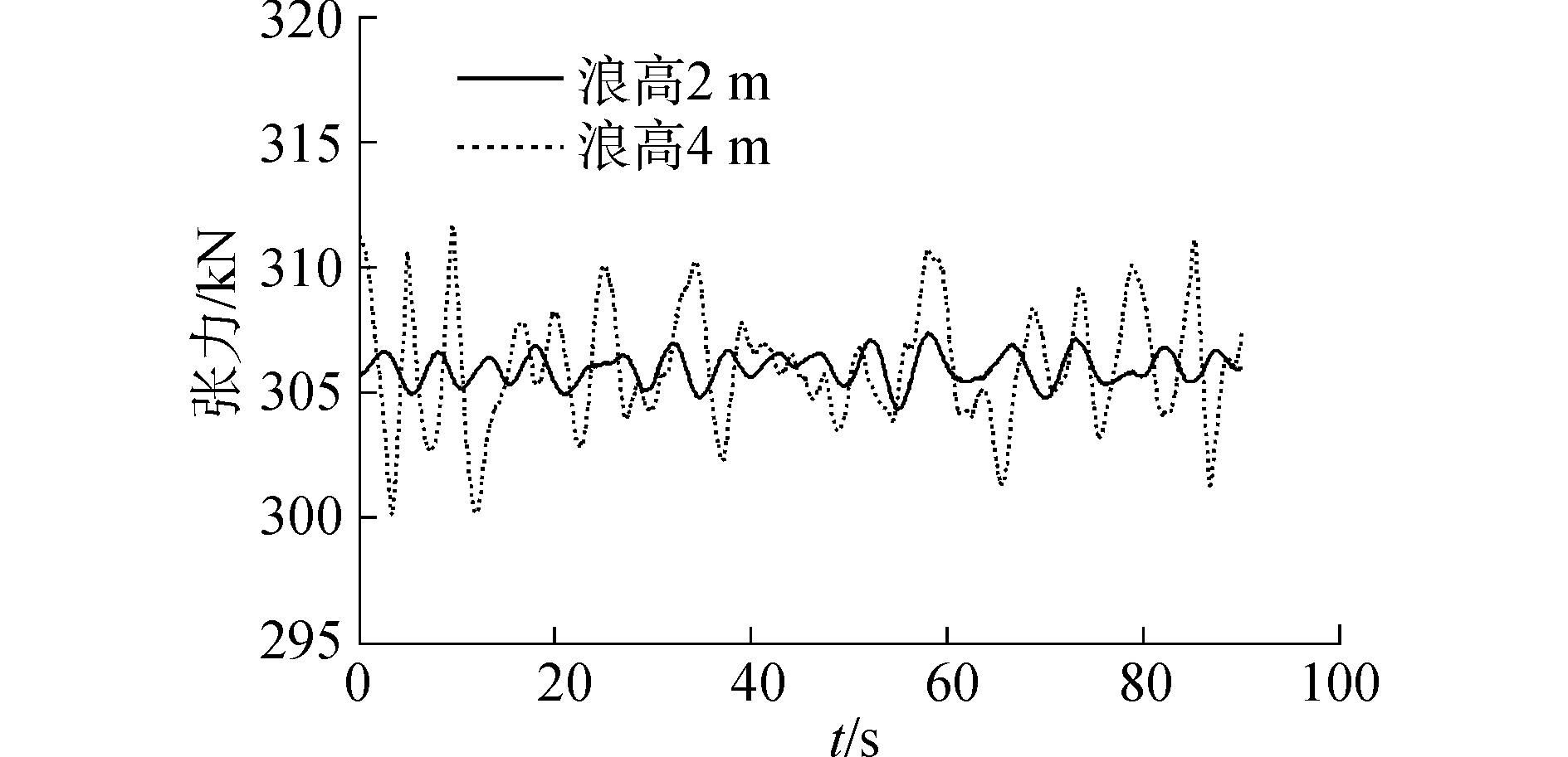
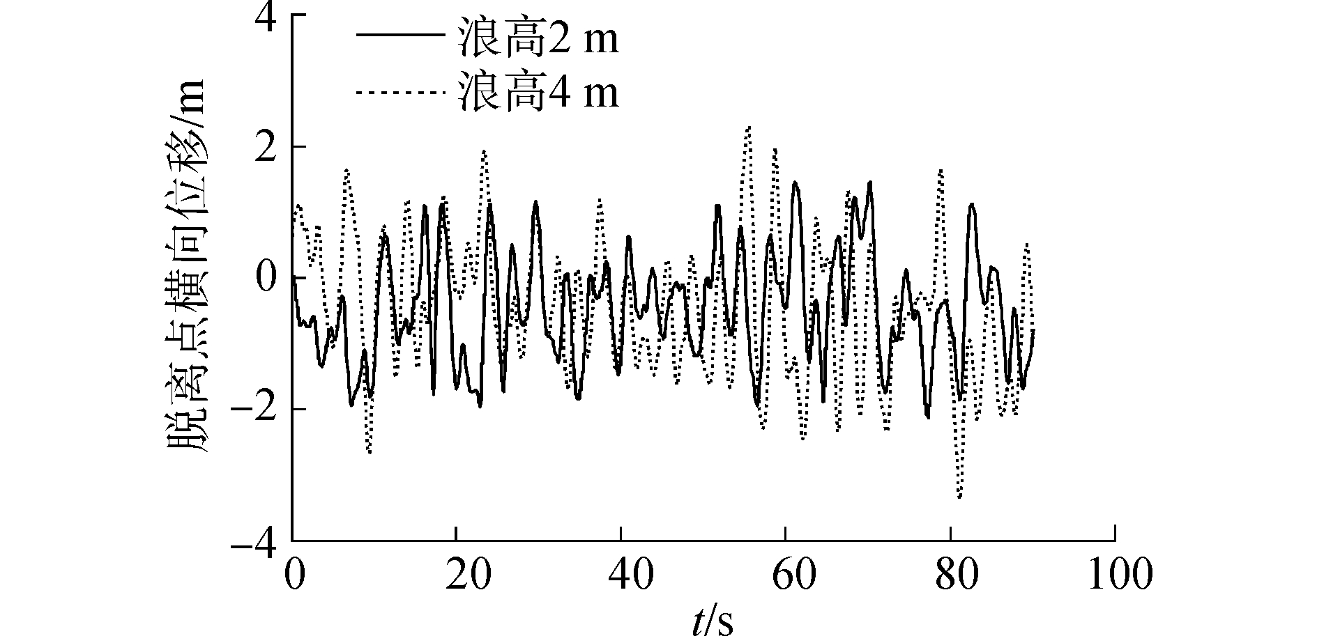
波浪传播方向90°,波浪周期10 s,在波浪浪高为2 m和4 m两种不同的海况下,管道和缆索受力及其横向振动位移如图 7、8所示。
|
Download:
|
| 图 7 管道触地时张紧器张力 Fig. 7 Tightener tension when pipeline hits seabed | |
|
Download:
|
| 图 8 管道脱离点横向位移 Fig. 8 Lateral displacement of pipeline release point | |
从图 7和8可以看出,2 m浪高海况下管道触地点最大张力为307.77 kN,管道脱离点最大横向位移为到2.2 m;4 m浪高海况下管道触底点最大张力达到了312.32 kN,管道脱离点横向位移达到了3.1 m。浪高增加时,船舶运动也越来越剧烈,使脱离点处振动幅度增加,船尾脱离点处横向偏移增大,这就会导致张紧器处的管道张力增大。
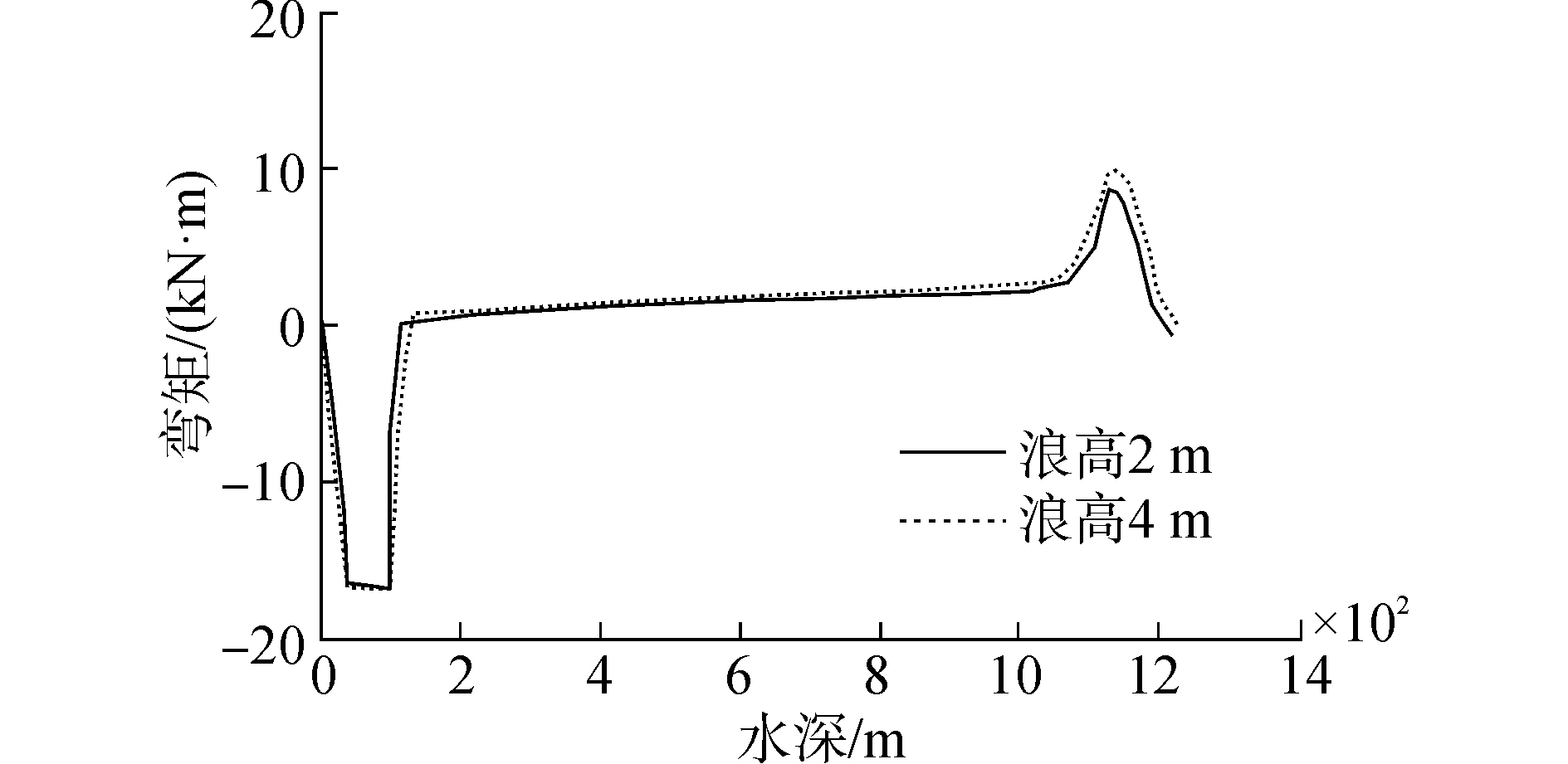
图 9所示为在不同海况作用下,管道触底时的弯矩分布图。
|
Download:
|
| 图 9 管道触底时的弯矩分布 Fig. 9 Pipeline bending moment distribution when hits the seabed | |
从图 9可以看出,在管道完全触底后,波高的变化对弯矩基本没影响,弯矩保持在16.25 kN·m左右,下弯段的弯矩随着海浪的增高,在200~300 m区段有增大趋势,其余部分管线弯矩变化不大。
图 10所示为管道下放长度为400 m和1 000 m时候在2 m浪高海况和4 m浪高海况下的横向位移曲线。

|
Download:
|
| 图 10 不同管道长度下管道横向位移曲线 Fig. 10 Lateral displacement under different pipeline length | |
从图 10可以看出,当管道铺设长度为400 m时,在浪高2 m海况下,管道横向振动位移在150 m左右处衰减为0,而在4 m浪高海况下,管道振动持续到200 m左右;当管道铺设长度为1 000 m时,在浪高4 m情况下,管道振动长度达到400 m,说明波高越大,管道震动越剧烈。
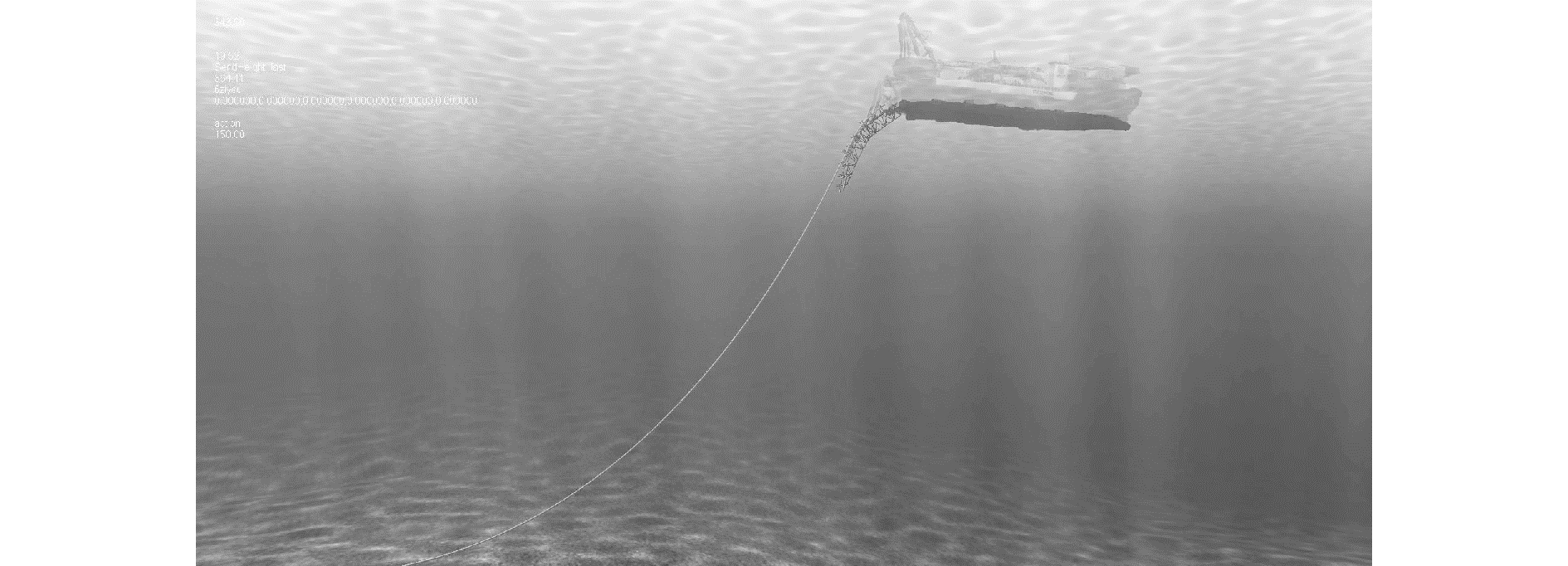
图 11为在船体不同横向激励作用下管道动态响应曲线,当船体没有横向位移仅有波浪载荷时,管道振动很小,随着船体横向位移的增大,管道悬空段波动越发剧烈。从图中可以看出管道在托管架附近的波动最明显,越靠近触底点管道振动越弱直至为零,管道振动受船体运动的影响最大。图 12所示为铺管视景仿真系统仿真三维视景图。

|
Download:
|
| 图 11 管道形态随在船舶运动激励下动态响应曲线 Fig. 11 Pipeline shape dynamic response curve under ship movement | |
|
Download:
|
| 图 12 铺管仿真系统视景 Fig. 12 Pipelaying simulation system scene | |
为了验证仿真结果,将仿真系统在2 m浪高下的结果与商业软件OFFPIPE同样参数下的计算结果进行对比(由海洋石油工程股份有限公司提供),对比结果如表 2所示。
| 表 2 仿真与OFFPIPE的运算结果比较 Tab.2 Results comparison of simulation and OFFPIPE |
从表 2的数据分析可知,仿真结果与商业软件计算结果误差保持在4%以内,准确性符合工程设计要求。
4 结论1) 基于"海洋石油201"船实测数据,建立了一套铺管视景仿真系统,可为铺管工作人员培训和海上铺管工程项目预演提供仿真平台,为国内第一个大型海底管道铺设的实时视景仿真系统。
2) 为了准确实现初始铺管作业的仿真模拟,将非线性大挠度梁理论应用于初始铺管计算,建立了管道和缆索耦合系统的数学模型。
3) 在管道初始铺设振动特性分析过程中,利用显式差分法对管线的动态振动进行求解。
4) 海况浪高由2 m增加到4 m,管道张力增大1.48%,管道弯矩基本无变化,管道振动长度增加33.33%。管道铺设长度越大,管道振动越剧烈。
5) 船舶运动对管道悬空段振动特性影响较大,当船舶横向位移达到5 m时,管道振动范围接近海底触地点处。
6) 仿真系统准确性满足工程实际需求,可为实际铺管作业进行工程预演模拟,及早发现问题,调整施工方案,降低海上铺管作业施工风险。
| [1] |
RONCONI R A, ALLARD K A, TAYLOR P D, et al. Bird interactions with offshore oil and gas platforms:review of impacts and monitoring techniques[J]. Journal of environmental management, 2015, 147: 34-45. DOI:10.1016/j.jenvman.2014.07.031 (  0) 0)
|
| [2] |
ZHU H, QI X, LIN P, et al. Numerical simulation of flow around a submarine pipe with a spoiler and current-induced scour beneath the pipe[J]. Applied ocean research, 2013, 41(6): 87-100. (  0) 0)
|
| [3] |
DUAN M L, WANG Y, ESTEFEN S, et al. An installation system of deepwater risers by an S-lay vessel[J]. China ocean engineering, 2011, 25(1): 139-148. DOI:10.1007/s13344-011-0012-y (  0) 0)
|
| [4] |
WEST C, ARMSTRONG S, MCMILLAN D, et al. S-lay installation of riser fairings for the independence hub[C]//Proceedings of the International Conference on Offshore Mechanics and Arctic Engineering, 2007: 515-525.
(  0) 0)
|
| [5] |
马小燕. 深水S型铺管作业中管线受力计算研究[D]. 哈尔滨: 哈尔滨工程大学, 2012. MA Xiaoyan. Calculation and study on force of pipeline in the deepwater S-lay operation[D]. Harbin: Harbin Engineering University, 2012. (  0) 0)
|
| [6] |
YANG L, SHI B, GUO Y. Study on dynamic angle of repose for submarine pipeline with spoiler on sandy seabed[J]. Journal of petroleum exploration & production technology, 2012, 2(4): 229-236. (  0) 0)
|
| [7] |
BAI Y, BAI Q. Subsea system engineering-subsea pipelines and risers-chapter 17[J]. Subsea pipelines & risers, 2005: 263-276. (  0) 0)
|
| [8] |
BAUER A M, BREITENBERGER M, PHILIPP B, et al. Nonlinear isogeometric spatial Bernoulli beam[J]. Computer methods in applied mechanics & engineering, 2016, 303: 101-127. (  0) 0)
|
| [9] |
花雷. 曲梁结构非线性大变形分析[D]. 扬州: 扬州大学, 2011. HUA Lei. The analysis for non-linnear large deformation of curved beams[D]. Yangzhou: Yangzhou University, 2011. (  0) 0)
|
| [10] |
李世荣, 孙云, 刘平. 关于Euler-Bernoulli梁几何非线性方程的讨论[J]. 力学与实践, 2013, 35(2): 77-80. LI Shirong, SUN Yun, LIU Ping. Discussion on the Euler-Bernoulli beam geometry nonlinear equations[J]. Mechanics and practice, 2013, 35(2): 77-80. DOI:10.6052/1000-0879-12-014 (  0) 0)
|
| [11] |
聂国隽, 仲政. 用微分求积法求解梁的弹塑性问题[J]. 工程力学, 2005(1): 59-62. NIE Guojun, ZHONG Zheng. Elasto-plastic analysis of beams by differential quadrature method[J]. Engineering mechanics, 2005(1): 59-62. (  0) 0)
|
| [12] |
ZIANI M, GUYOMACRH F. An autoadaptative limited memory Broyden's method to solve systems of nonlinear equations[J]. Applied mathematics and computation, 2008, 205(1): 202-211. DOI:10.1016/j.amc.2008.06.047 (  0) 0)
|
| [13] |
于佳利, 李富智, 杨慧. Landau-Lifshitz方程的显式差分法[J]. 西南民族大学学报(自然科学版), 2016(3): 329-335. YU Jiali, LI Fuzhi, YANG Hui. Explicit finite difference scheme for Landau-Lifshitz equation[J]. Journal of Southwest University for Nationalities (natural science edition), 2016(3): 329-335. (  0) 0)
|
| [14] |
昝英飞. 深水铺管起重船起重作业模拟系统方案设计[D]. 哈尔滨: 哈尔滨工程大学, 2011. ZAN Yingfei. Concept design of lifting operation simulation system of a deepwater pipe-laying crane vessel[D]. Harbin: Harbin Engineering University, 2011. (  0) 0)
|
| [15] |
谢鹏. 超深水S型铺管的上弯段关键力学问题研究[D]. 大连: 大连理工大学, 2014. XIE Peng. Study on mechanical problems of overbend section in ultra deepwater S-lay operations[D]. Dalian: Dalian University of Technology, 2014. (  0) 0)
|
| [16] |
许元革. 深水铺管起重船作业实时动力学仿真研究[D]. 哈尔滨: 哈尔滨工程大学, 2012. XU Yuange. Real-time dynamic simulation research on the deepwater pipe-lay crane vessel operation[D]. Harbin: Harbin Engineering University, 2012. (  0) 0)
|
| [17] |
周俊. 深水海底管道S型铺管形态及施工工艺研究[D]. 杭州: 浙江大学, 2008. ZHOU Jun. Investigation of configuration and construction technology of S-lay for deepwater submarine pipelines[D]. Hangzhou: Zhejiang University, 2008. (  0) 0)
|
| [18] |
李志刚. 深水海底管道铺设技术[M]. 北京: 机械工业出版社, 2012. LI Zhigang. Submarine pipeline laying and technology in deep water[M]. Beijing: China Machine Press, 2012. (  0) 0)
|
| [19] |
BRU R, CERDAN J, MARIN J, et al. Preconditioning sparse nonsymmetric linear systems with the Sherman-Morrison formula[J]. Siam journal on scientific computing, 2003, 25(2): 701-715. DOI:10.1137/S1064827502407524 (  0) 0)
|
| [20] |
DROZYNER P. Determining the limits of piping vibration[J]. Physical review:A, 2011, 84(5): 285-297. (  0) 0)
|
| [21] |
梁立孚, 刘宗民, 刘殿魁. 非保守薄壁结构系统的广义拟余Hamilton原理及其应用[J]. 工程力学, 2008, 25(10): 60-65. LIANG Lifu, LIU Zongmin, LIU Diankui. Generalized Hamilton Ouasi-complementary energy principle of non-conservative thin-wall structural system and its applicatioon[J]. Engineering mechanics, 2008, 25(10): 60-65. (  0) 0)
|
| [22] |
张磊, 王其波. 微分方程数值解的隐显式Runge-Kutta方法[J]. 科技信息, 2012(33): 233-234. ZHANG Lei, WANG Qibo. Numerical solution of differential equation using explicit-implicit Runge-Kutta method[J]. Science & technology information, 2012(33): 233-234. (  0) 0)
|
 2018, Vol. 39


