 2017, Vol. 60


2 Key Laboratory of Mineral Resources, Institute of Geology and Geophysics, Chinese Academy of Sciences, Beijing 100029, China
The integrated Jurassic coalfields of Xinjiang Uyghur Autonomous Region are shallow buried and mostly exposed. Spontaneous combustion from the beginning of geological history is increasingly intensified with modern human activities and the disordered mining of small coal mines in recent decades, resulting in huge loss of resources and serious environmental disaster. During the coalfield fire extinguishing and managing process, in addition to the manual inspection (Xinjiang Coal Field Fire-Fighting Engineering Bureau, 2000, 2006), airborne observation (Radke et al., 2000; Zhou X H and Lin Y, 2009) and satellite monitoring (Christopher et al., 2009), on-site detection of small and isolated distribution fire areas need a remote controlled, long-term, real-time and direct temperature measurement method. We employ high resolution resistivity method to detect the center and range of combustion area (Shi et al., 2013), and utilize the modern wireless sensor network (WSN) technology (Estrin et al., 1999) to monitor on-site temperature and transmit it with all kinds of parameters detected by integrated electromagnetic method. This method gives full play to the optimization and integration of Internet in geophysical exploration, and the innovation achievements of Internet are deeply integrated into the traditional geological prospecting field, which is of great significance to promote innovation and production capacity of coal geological exploration.
This paper introduces a kind of perpetual wireless internet remote monitoring system that has the functions of electromagnetic prospecting, continuous acquisition and remote control. The wireless sensor internet remote monitoring system throughout Xinjiang is different from WSNs that are used for the environment (Kerkez et al., 2012), human health (Blumrosen et al., 2010), city (Watteyne and Prister, 2011), structure (Pakzad et al., 2008), agricultural (Pierce and Elliott, 2008), coal mine (Zhu and Xie, 2013) and landslides (Ramesh, 2014) monitoring. There are many questions should be solved: the acquisition and return of measuring results from comprehensive electromagnetic detection, continuous energy supply for permanent WSN nodes, automatic connection of communication link in remote data transmission without manual intervention, etc. We connected the WSN node, which can store and transmit detection result wirelessly, to the pole-dipole device used in high resolution resistivity method. The protection circuit of solar power device and the peripheral circuit of WSN nodes solved the energy problem from two aspects of open source and throttling. The heartbeat packet mechanism with automatic reconnection and bidirectional communication protocol ensured the reliable transmission of data and control instructions. From November 2011, the wireless sensor internet monitoring system deployed in 12 fire areas of Xinjiang, such as Songshutou, Daquanhu and Kueraken has been going on for 45 months. Battery electricity is enough, communication link is unblocked, observation data returned from the monitoring area is complete and reasonable, and control instruction sent to monitoring area is executed correctly.
2 STRUCTURE OF THE WIRELESS SENSOR INTERNET REMOTE MONITORING SYSTEMWireless sensor internet remote monitoring system (Fig. 1) mainly includes field data collection network, remote transmission system and monitoring central server. The uplink of this system is as follows: in the field data collection network deployed in fire area, the pole-dipole device detects and sends the electromagnetic parameters to the sensor node, which transfers the electromagnetic parameters and the measured temperature by itself to sink node; then, all of these data are transmitted wirelessly to central server across GRPS module, mobile system and Internet of remote transmission system. In the same way, the controlling information could be transmitted from server to on-site sensor node by the downlink of system.

|
Fig. 1 Structure of the wireless sensor internet monitoring system of fire area |
The pole-dipole device, a commonly used equipment of high resolution resistivity method, was initially developed and applied in military field by the U.S. army and mining bureau in the 1970 s. With the further research of the high resolution resistivity method and related technology theory, and with improvement and perfection of detection methods and instruments, this method was applied in the underground cavity, coal mine goaf, highway subgrade, archaeology and shallow exploration and achieved good geological effect in the last century after 1980s. The pole-dipole device that has small volume effect and sensitive to isolated abnormal body is designed for detecting underground cave.
During the development of the coal fire sensor node, we choose JN5139 chip as the hardware platform connected with the pole-diploe device, design the minimum functional requirements of peripheral circuit. By these ways, we complete the low power consumption sensor node design, shown in Fig. 2, for transmitting the detected electromagnetic parameters. The monitoring center is able to master the working environment and conditions of collection network, which is far away from the infrastructure and unattended in the wilderness. A 2.4 GHz wireless transceiver chip and a 32 bit RISC microprocessor are integrated in JN5139 chip, which can be used as a common sensor node or a sink node with executable, task scheduling, data transfer and energy calculation and coordination functions (Jennic, 2010).

|
Fig. 2 Sensor node interior structure |
Continuous energy of permanent field monitoring network is provided by solar power supply device. Because the maintenance cycle of common solar power supply device is short and the remote monitoring system has higher request for free maintenance, a free maintenance solar power supply device should be designed.
When the sunlight is enough, the solar panel can charge the battery through the charge protection circuit shown in Fig. 3a and directly supply power to the node through voltage stabilizing circuit shown in Fig. 3b. When the sunlight is not enough or in the night, if the solar panel output voltage is lower than the battery voltage, transistors Q1 is reverse blocking, and then, node is powered by the battery. Three-terminal voltage regulator TL431 and adjustable resistance W1 form voltage regulation circuit, which prevent the battery from overshoot by setting the charge threshold. With the increase of the battery voltage, the charging current decreases gradually to trickle charging, which ensure the battery will not overcharge. Transistors Q2 and adjustable resistance W2 are used to adjust the size of the trickle charge.

|
Fig. 3 Charge and discharge protection circuit of solar power device (a) Charge protection circuit; (b) Discharge protection circuit; (c) Charge and discharge protection circuit board; (d) Solar power device with charge and discharge protection circuit board. |
In Fig. 3b, the DC-DC circuit consisting of voltage regulator module HT7330 and capacitances C1-C4 also act as discharge protection circuit with simple structure and low power consumption (0.3 mA). When the input (port 1) voltage of HT7330 is greater than or equals to 3.2 V (fully charged battery voltage value), the output (port 2) voltage is stable at 3 V and supplies power to node through VIN pin. When the battery voltage is down to 2.7 V, HT7330 output voltage gradually decreases from 3 V to stop working, and output current reduces to microampere level for discharge protection. Small capacitors C1 and C3 filter out high frequency noise and impulse interference. Large capacitor C2 and C4 filter out low frequency noise. Fig. 3c shows the charge and discharge protection circuit board.
The average daily energy consumption of data acquisition and transmission of the sensor node is 0.126 Ah. In order to have enough energy in continuous overcast, rain, fog, snow and winter short sunshine, we equip the sensor node with a 3.2 V 4 Ah battery. By matching 5 W 6 V solar panels, battery can be charged full with 700 mA charging current about 6 hours (less than a day). In order to adapt to the 50 ℃ high temperature in summer and near-40 ℃ low temperature in winter in the wilderness, we adopt the lithium iron phosphate batteries with better high and low temperature performance than lead-acid battery. Fig. 3d is the power supply device with the charge and discharge protection circuit. Once charge can maintain node work about 30 days, enough to cope with the extreme weather conditions for a long time, so that the entire monitoring network to achieve uninterrupted data collection.
5 BIDIRECTIONAL COMMUNICATION AND REMOTE CONTROL TECHNOLOGY OF SYSTEM 5.1 Heartbeat Packet MechanismField monitoring data is transparently transferred to the server in the form of IP packet following TCP/IP protocol through GPRS module. With the rapid development of mobile business, network congestion and accidental disconnection happen occasionally. To this end, the heartbeat packet technology (Gao et al., 2009; Striegel and Manimaran, 2008) is used in GPRS module. Then the GPRS can automatically resume communication without human intervention, so can ensure stable communication and reliable transmission of data. The heartbeat packet is a special data packet sent by GPRS module to occupy channel and keep the link unblocked during the data sending interval. When communication is unexpectedly interrupted, the link should automatically resume by the heartbeat packets. The packet length of general data is an important parameter in GPRS communication, big packet is prone to loss of data and small packet is prone to unnecessary overhead. Fig. 4 is the configuration interface of GPRS with heartbeat package mechanism. We set the heartbeat cycle to 60 s and the size of general data package to 300 bytes. Test results show that the packet loss rate of transfer data is reduced from maximum 7% without the heartbeat packets to 0.31% with heartbeat package.

|
Fig. 4 Configuration interface of GPRS with heartbeat |
The bidirectional communication protocol for uplink and downlink includes: unit format, content, meaning, send and receive sequence of the data for correct transmission and analysis.
Table 1 shows the data package format in uplink with 18 bytes. Thereinto, packet header has 6 bytes and signal has 12 bytes. The main fire area number is the label of field fire area, occupying 1 byte. In a main fire area, there can be many sub fire areas deployed each with a unique GPRS. Life and security field takes 1 byte each, reserved for building network later. Data field consists of the actual monitoring data and the forwarded resistivity value.
|
|
Table 1 Data package format of uplink |
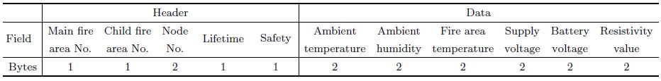
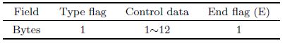
Table 2 shows the data package format of downlink. The type flag field of 1 byte represents the type of control information. For example, "0" represents network clock correction and "1" represents sample interval modification. This field can be set a maximum of 255 types of control, which reserve extended space for later development. The size of the control information field filled in with the specific control data can be set variable value between 1~12 bytes. The end flag occupying 1 byte, character "E", indicates the end of data package.
|
|
Table 2 Data package format of downlink |
On the server side, the staff can adjust the on-site monitoring network parameters via sending down link of control command. The controlling data including RTC clock correction (Cao et al., 2012) and sampling interval adjustment command are sent with the confirmed frame via the downlink after receiving each field data. According to the fire area ground temperature change speed, authorized user can set the sampling interval in the range of 1~24 hours from the initializing 1 hour. If there has no command, the sampling interval remains the same. Authorized user also can send the clock calibration to the on-site network. Downlink control command is parsed in the sink node, and then forwarded to the sensor nodes to be performed together.
6 OPERATING RESULT OF THE SYSTEMThere are 255 main fire areas in the whole Xinjiang fire area monitoring system at most, and each main fire area includes 255 sub fire areas at most. So far the monitoring networks were deployed at 12 main fire areas, such as Songshutou in northern Xinjiang and Kueraken in southern Xinjiang, as shown in Fig. 5.

|
Fig. 5 Arrangement plan of Xinjiang fire area wireless sensor internet monitoring system |
Each sub network (such as Songshutou fire area network shown in Fig. 6a) is composed of 1 sink node (Fig. 6b) and 4~10 sensor nodes (Fig. 6c). GPRS module in the sink node of each subnet transmitted monitoring data to the Xinjiang Coal Field Fire-Fighting Engineering Bureau monitoring center server in Ürümqi.

|
Fig. 6 The deployment of nodes and the network at the scene of the fire area observation (a) Monitoring network at Songshutou (the distance between sink node and sensor node is about 200 m); (b) Sink node; (c) Sensor node. |
Figure 7a shows GPRS status of 12 fire areas including the fire area No. and name, the sampling interval, online or offline of communication, the recent connection time, alarm status, the number of nodes etc., at 12 o'clock on July 03, 2015. The communication status displays online when GPRS is working at current moment, or offline when not. If the fire area node monitoring data exceed the setting alarm threshold, alarm status displays abnormal. According to the fire area ground temperature change speed, authorized user can set the sampling interval in the range of 1~24 hours and send the clock calibration to the observation site network. Fig. 7b shows the query data of 0401 Jimsar Shuixigou fire area including the sink node No.1 and sensor node No.2-No.6 on July 02, 2015. The ground temperature of this fire area is more than hundred ℃ that is an anomalous event. Therefore, the corresponding alarm status of 0401 fire area in Fig. 7a is set as abnormal. Data sampling interval is readjusted to the shortest interval of 1 hour to increase the frequency of observation. Numerical values of ambient temperature, ambient humidity, working voltage and battery voltage are in the normal range.

|
Fig. 7 On-site data received by Ürümqi monitoring center (a) Sub fire area GPRS list; (b) Data of No.1 fire area in Jimsar Shuixigou. |
Based on different resistivities of coal oxidation in low-temperature and when burning, high resolution resistivity method is used to detect the coal fire burning center. In coal management stage, we can use this method to estimate the extent of combustion area. Detected data and fire temperature are transmitted to the remote monitoring center in Ürümqi by the wireless sensor internet monitoring system of Xinjiang coal fire area. In addition to the manual inspection, airborne observation and satellite monitoring method, this wireless monitoring system provides a real-time and on-site temperature measurement method for Xinjiang Coal Field Fire-Fighting Engineering Bureau. The designed sensor node connects with the pole-dipole device, which can convert the electromagnetism parameters to electrical signal, then store and send. The temperature range extends to-40 ℃~1300 ℃, which covered the coal seam temperature changing range from the combustion of accumulated temperature to the flameout after governance and the formation temperature changing range in winter. We adopt many technologies in the application oriented research and development process, such as external clock circuit design for WSN node, energy throttling and open source parallel strategy, heartbeat package mechanism in mobile communication network link and so on, to provide technical support for a remote, maintenance free and permanent WSN. Thereby, the solar power supply device with charge and discharge protection circuit offers enough power capacity for the node function extension. So far, Xinjiang coal fire area WSN remote monitoring system has been running for three years and nine months and collected data more than 1100000. All of these data and subsequent data will be stored in Ürümqi monitoring center server, and provide the basis for fire area governance and management. In the process of forming the whole Xinjiang WSN system in the future, GPRS will be upgraded with the development of 4G mobile network. More information such as gas, image and video will be observed and transmitted. Xinjiang coalfield will be placed in a full range, all-weather continuous monitoring.
ACKNOWLEDGMENTSThis project is funded by the Science and Technology Aid Xinjiang Project (201191210) and the GTZ Corporation of Germany (83045640).
| [] | Blumrosen G, Uziel M, Rubinsky B, et al. 2010. Tremor acquisition system based on UWB wireless sensor network. //2010 International Conference on Body Sensor Networks. Singapore: IEEE, 187-193. |
| [] | Cao Q H, Yan S, Zhu N, et al. 2012. Synchronous Recovery Mechanism for Wireless Sensor Networks with Long-time and Depth Sleep (in Chinese). CN 102821446A, 2012-12-12. |
| [] | Christopher S A, Gupta P, Nair U. 2009. Satellite remote sensing and mesoscale modeling of the 2007 Georgia/Florida fires. IEEE Journal of Selected Topics in Applied Earth Observations and Remote Sensing , 2 (3) : 163-175. DOI:10.1109/JSTARS.2009.2026626 |
| [] | Estrin D, Govindan R, Heidemann J, et al. 1999. Next century challenges: Scalable coordination in sensor networks. //Proc. 5th Annual ACM/IEEE Int'l Conf. on Mobile Computing and Networking. Seattle, Washington, USA: IEEE, 263-270. |
| [] | Gao C, Du J L. 2009. Adaptive heartbeat mechanism for meteorology operation command system based on GPRS. //Proceedings of the 1st International Conference on Information Science and Engineering (ICISE). Nanjing, China: IEEE, 2522-2525. |
| [] | Jennic. JN-DS-JN5139-xxx-Myy 1v6. 2010. Sheffield: Jennic Ltd, 1-2. |
| [] | Kerkez B, Glaser S D, Bales R C, et al. 2012. Design and performance of a wireless sensor network for catchment-scale snow and soil moisture measurements. Water Resources Research , 48 (9) : W09515. |
| [] | Pakzad S N, Fenves G L, Kim S, et al. 2008. Design and implementation of scalable wireless sensor network for structural monitoring. Journal of Infrastructure Systems , 14 (1) : 89-101. DOI:10.1061/(ASCE)1076-0342(2008)14:1(89) |
| [] | Pierce F J, Elliott T V. 2008. Regional and on-farm wireless sensor networks for agricultural systems in Eastern Washington. Computers and Electronics in Agriculture , 61 (1) : 32-43. DOI:10.1016/j.compag.2007.05.007 |
| [] | Radke L F, Clark T L, Coen J L, et al. 2000. The WildFire Experiment (WiFE):Observations with airborne remote sensors. Canadian Journal of Remote Sensing , 26 (5) : 406-417. DOI:10.1080/07038992.2000.10855272 |
| [] | Ramesh M V. 2014. Design, development, and deployment of a wireless sensor network for detection of landslides. Ad Hoc Networks , 13 : 2-18. DOI:10.1016/j.adhoc.2012.09.002 |
| [] | Shi X X, Yan S, Fan T, et al. 2013. Study on the integrated electromagnetic method detection technology of the coal spontaneous combustion. //Chinese Geophysics 2013 (in Chinese). Beijing: Chinese Geophysical Society, 1024-1025. |
| [] | Striegel A, Manimaran G. 2002. Edge-based fault detection in a DiffServ network. //Proceedings of the 2002 International Conference on Dependable Systems and Networks. Washington, DC, USA: IEEE, 79-88. |
| [] | Watteyne T, Pister K S J. 2011. Smarter cities through standards-based wireless sensor networks. IBM Journal of Research and Development , 55 (1-2) : 7:1-7:10. |
| [] | Xinjiang Coal Field Fire-Fighting Engineering Bureau. 2000. The Xinjiang Uygur Autonomous Region coalfield fire control planning (in Chinese). Ürümqi, 1-16. |
| [] | Xinjiang Coal Field Fire-Fighting Engineering Bureau. 2006. Xinjiang coalfield fire-fighting planning (in Chinese). Ürümqi, 1-8. |
| [] | Zhou X H, Lin Y. 2009. The application of information extraction of aerial infrared remote sensing images in Daling coalfield, Inner Mongolia Autonomous Region. Journal of Northwest University (Natural Science Edition) (in Chinese) , 39 (5) : 837-840. |
| [] | Zhu Y G, Xie L Q. 2013. The application of wireless sensor network in coal mine monitoring. Advanced Materials Research , 694-697 : 1043-1046. DOI:10.4028/www.scientific.net/AMR.694-697 |