 2016, Vol. 59


2 China Research Institute of Radiowave Propagation, Henan, Xinxiang 453003, China
With the application of unbalanced drilling and air drilling technology,the advantage of EM-MWD(Electromagnetic wave measurement while drilling)technology is more clear,because it is less affected by drilling medium. The transmission of electromagnetic wave does not depend on the circulation of drilling medium. It can reduce MWD occupation of drilling time,improve drilling efficiency(Fan et al.,2013). Therefore,in recent years,electromagnetic wave measurement while drilling technology has become a hot research subject.
Theoretical research of electromagnetic wave transmission can be divided into two categories,one is based on low frequency field characteristics of the equivalent approximation method of equivalent transmission line method(Wait,1973; Liu,1988; Xiong et al.,1995,Fan et al.,2013); the other is based on solving the field equations boundary value problems by numerical methods(Lovell,1993; Li et al.,2013). Based on the research of first method,the model is simplified,the formation is simplified as homogeneous medium(Wait et al.,1973; Liu,1988; Xiong et al.,1995)or not considering casing(Fan et al.,2013)and the difference with actual situation. Based on the study of second methods,finite element method(Lovell,1993)can be used to solve the problem, for large area and complicated boundary conditions. Using excitation source equivalent relation,combined with the numerical mode matching method,Li et al established a horizontally and radially layered theoretical model (Li et al.,2014),but the results were not compared with the field test data,and the model did not contain high conductivity formation and high resistance formation. In this paper,the computation results and field test results are used to verify the correctness of the theoretical model,and the impact of casing,mud,high conductivity formation,and high resistance formation on signal transmission is calculated and analyzed.
2 PROBLEM DESCRIPTIONSThe transmitter encodes and modulates the measurement information,then injects current into the antenna. The signal via the transmission channel composed of formation,drill string,casing,and mud goes to the surface; by measuring the potential difference between wellhead and a place at a certain distance away from the wellhead,the information is collected. The basic principle is shown in Fig. 1. The problem is simplified,the formation is horizontal,the well is vertical,and the model is axially symmetrical. The simplified physical model of this problem is to consider the axial symmetry model of drill string,borehole,mud,casing and horizontal layer. In the model,the air above the surface is considered as a layer.

|
Fig. 1 EM transmission system |
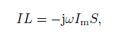
Hertz electrical dipole is known to be equivalent to that generated by a small magnetic current loop when
|
(1) |
in the formula,I,Im is respectively the current intensity and the magnetic current intensity,and L,S respectively the length of the electric dipole and the area of the magnetic flow loop.
The drill stem is regarded as high conductivity medium and a current source as the excitation source, the source length is the insulating segment length. If the current source is divided into a number of infinitesimal current element,each a small current element using the equivalent relationship(formula 1),the magnetic flux ring radius is set according to the method of reference (Li et al.,2014). The magnetic field of a magnetic flux ring can be calculated by NMM,the total field is obtained by adding the fields of all magnetic flow rings.
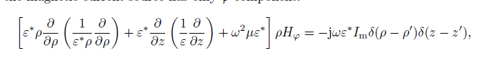
3.2 NMM TheoryFor a source of magnetic flux loop in the two-dimensional axisymmetric inhomogeneous media,the H field generated by the magnetic current source has only φ-component:
|
(2) |
where ε* is complex permittivity; in lossy medium it is related to conductivity and is a complex number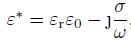
|
(3) |
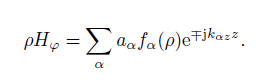
In the formula,fα(ρ),kαz and aα are the eigenfunction of α model,propagation constant and field amplitude in the z direction respectively. In the layered medium,the generalized assembled reflection matrix is used to describe the coupling effect of different eigen modes in the vicinity of the interface and the multiple reflection (Chew,1990; Nie et al.,1992).
In this paper,we use the piecewise trigonometric basis functions to expand the radial field,and apply the radiation condition and the symmetry condition(Nie et al.,1992). The magnetic field in the study area can be obtained by calculation.
In the calculation of the problem by NMM key attention should be paid to truncation boundary and radial split,through the actual calculation,it is found that the truncation boundary of 1.5 to 2 wavelength is appropriate,which can meet the precision requirement without adding extra difficulty to analysis and calculation because of too large radial distance; in the radial medium boundary partition should be encrypted,the partition rationality can be judged on the basis of whether the results meet the laws of physics,and the numerical stability can be assessed based on effect of increasing or decreasing dividing points on the calculation result.
3.3 Surface Potential and Input Impedance of AntennaThere is a relationship between the electric and magnetic fields according to Maxwell Law:
|
(4) |
|
(5) |
|
(6) |
The receiving potential difference is actually the integral of the radial component of the surface electric field between the two receiving points.
|
(7) |
Esρ is the radial component of the surface electric field.
Therefore the input voltage of the antenna
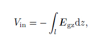
|
(8) |
l is the length of the insulating section. Egz is the axial component of the electric field on the surface of the insulation section. Iin as the excitation current is known,the input impedance of the antenna can be calculated:
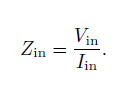
|
(9) |
The input impedance of the transmitting antenna is independent of the current excitation and the voltage excitation,and the two excitation modes can be established by formula(9).
4 CALCULATIONS AND ANALYSISTo verify the correctness of the theoretical model laboratory model or field test can be used,the results of theoretical calculations and field measurements are used to verify the correctness and applicability of the theoretical model. On this basis the factors affecting signal transmission are analyzed.
4.1 Theory Model ValidationThe working frequency in the field test is 4.5 Hz,the transmitting power is 10 W and receiving distance is 75 m,borehole diameter is 216 mm. Casing length is 545 m,outside diameter is 245 mm,inside diameter is 217 mm,the stem diameter is 217 mm,the drill string length below the insulating segment is 21.5 m,mud resistivity is 1.1 m. The formation resistivity(according to logging curve)and the simplified layer model for calculation are shown in Fig. 2. The amplitude of ground receiving signal calculated with the theoretical model at different depth is compared with the measurement results,as shown in Fig. 3. We can see that the general trends of signal attenuation with depth are consistent,only the difference between calculated and measured value varies at different depths. The author thinks that the deviation between the calculated and the measured results is caused by the model simplification and the electric parameter approximation. The comparison between the calculated value and the measured value can verify the correctness of the theoretical model.

|
Fig. 2 Formation resistivity and theoretical model |

|
Fig. 3 Calculated results and measured results |
From Fig. 3 we can see that the signal attenuation trend with the depth calculated by the equivalent transmission line method is consistent with the measured results,but the method can not take into account the influence of the casing and the high conductive layer,high resistance layer and so on. In this paper,we considered the influence of these factors,which is in better accord with the real situation; the method can be applied to the receiving signal amplitude changes to give a reasonable explanation.
4.2 Channel AnalysisUsing the theoretical model to calculate and analyze the factors that affect the signal transmission makes easy to understand the problem. The propagation of electromagnetic wave is attenuated by the formation(lossy medium),and the higher the frequency the more serious the attenuation. In order to increase the transmission distance,we need to use a lower frequency. For comparison,we change a certain parameter,and the other parameters remain unchanged. Unless otherwise specified,the transmitting power is 1 W,working frequency is 3 Hz,the drill string length below insulating short section is 10 m,drill pipe diameter 112 mm,borehole diameter 120 mm,casing and drill pipe conductivity 1.0×10⁶ S·m−1,formation resistivity 2 m,without casing, receiving distance 70 m,mud resistivity and formation resistivity are same.
4.2.1 Formation resistivityFigure 4 shows the attenuation curves of the received signal for three kinds of formation. From the figure it can be seen that with the depth increase the received signal becomes smaller,and the decay is approximately exponential; the formation resistivity has a very significant impact on the transmitted signal,the higher the resistivity of the formation,the slower the signal attenuation,the larger the surface receiving signal.

|
Fig. 4 Attenuation curves for different formation resistivity |
For three working frequencies,the receiving signal changes with depth as shown in Fig. 5. It can be seen that the higher the frequency of signal the faster the attenuation. Therefore,in practice the working frequency is in a few Hz to 10 Hz range. And because the frequency and the information transmission rate are related, the higher the frequency,the higher the information transmission rate. In order to obtain more information per unit of time,as long as the transmission depth meets the needs of the situation,the higher operating frequency should be selected.

|
Fig. 5 Attenuation curves for different frequency |
The drill stem is connected by the series of drill pipe(each length about 9 m),with the increase of the depth,the number of drill pipe increased,the contact resistance between the drill pipe and drill pipe,and drill stem is not a perfect conductor. Therefore,it is necessary to discuss the influence of conductivity of the drill string. In Fig. 6 the formation resistivity is selected as 10 m,it can be seen from the figure that,the better the drilling stem conductivity is,the more advantageous to the signal transmission,and the signal attenuation is smaller. The excitation mode of electromagnetic wave transmission used the conductivity of the drill pipe to full advantage.

|
Fig. 6 Attenuation curves for different drill stem conductivity |
In practice casing is usually used to protect shallow borehole,it will have an impact on signal transmission. There is 300 m casing in the theoretical model,casing outside diameter is 120 mm,inside diameter 140 mm and conductivity is 1.0×10⁶ S·m−1. From Fig. 7 we can see that,when transmitting in the casing,the signal became smaller,out of the casing,the signal was slightly larger. This is because the shielding effect to transmission in the casing,when out of the casing,the casing plays a guiding role for the signal. This is in agreement with the conclusion of the literature(Liu,1988).

|
Fig. 7 Casing effect for EM transmission |
The actual formations are far from homogeneous,often have high resistance or high conductivity formation. Analysis of the impact of high resistance layer and high conductivity layer for the signal transmission can help understanding and explaining the phenomenon of field operation. In Fig. 8 the formation resistivity of the theoretical model is 10 Ω m,and in the depth of 1000~1100 m it contains a high resistance formation of 1000 m. From Fig. 8,we can see that after entering the high resistivity layer,the signal is smaller than that of the homogeneous model. In Fig. 9,the theoretical model has a formation resistivity of 10 Ω m,but contains a high conductivity formation of 1 m at depths of 1000~1100 m. Compared with the signal in the homogeneous model,the signal becomes larger after entering the highly conductive layer,and the signal attenuation is fast in the high conductivity layer.

|
Fig. 8 High resistivity formation effect for EM Transmission |

|
Fig. 9 High conductivity formation effect for EM transmission |
The effect of high resistivity formation and high conductivity formation mainly has two aspects,one is on the antenna input impedance and the other is on signal transmission attenuation. Entering the high resistance layer,the input impedance of the antenna suddenly becomes higher,antenna current becomes small,the signal becomes smaller; out of the high resistivity layer,the input impedance of the antenna is recovered,but signal attenuation is small in high resistivity layer,therefore the signal is slightly larger than homogeneous formation. The influence of high conductivity layer can be analyzed in the same way,but the high conductivity layer will affect the transmission attenuation more obviously,so in Fig. 9 the signal after passing through the high conductivity layer differs more from the uniform stratum.
4.2.6 MudIn order to cool the drill bit,reduce friction,control pressure,protect borehole and formation,mud is used in drilling. With the development of drilling technology, air,oil base and other special mud is used. The conductivity of the mud has large difference. In the following calculation,the well depth is 2000 m, the receiving signal varies with the mud conductivity. From Fig. 10 it can be seen that,for ordinary mud of conductivity 0.01~1.0 S·m−1,the influence on signal transmission is small. But the high resistivity mud has a certain effect on the signal transmission,the higher the mud resistivity,the smaller the signal transmission attenuation.
|
|
Fig. 10 Signal amplitude vs. mud conductivity |
(1) The theoretical model of electromagnetic wave signal transmission is established by the source equivalence relation and NMM method. The correctness and applicability of the theoretical model are verified by comparing the calculated results with the field test results.
(2) By calculation and analysis the formation resistivity,working frequency,drilling stem conductivity are the main factors affecting the signal transmission; casing,high resistivity layer,high conductivity layer influence signal transmission to a certain degree; ordinary mud has little influence on the signal transmission,whereas high resistivity mud results in smaller signal transmission attenuation.
(3) The study considered the air layer. It is found from the calculation that the presence of the air layer Fan Y H et al.: Channel Analysis of EM-MWD Based on NMM 171 magnifies the ground field by an amount depending on the formation resistivity,the depth of excitation source, and other factors. The effect of air layer need to be further discussed.
(4) The theoretical model is based on the axisymmetric condition,hence has certain limitations. For analyzing the characteristics of signal transmission of directional wells,a complex theoretical model should be established.
AcknowledgeThis work was supported by the National Natural Science Foundation of China(61231001).
| [1] | Chew W C. 1990. Waves and Fields in Inhomogeneous Media. New York:Van Nostrand Reinhold. |
| [2] | Fan Y H, Nie Z P, Li T L. 2013. EM channel theory model and characteristics analysis for MWD[J]. Chinese Journal of Radio Science (in Chinese), 28 (5): 909–914. |
| [3] | Li W, Nie Z P, Sun X Y, et al. 2014. Numerical modeling for excitation and coupling transmission of near field around the metal drilling pipe in Lossy formation[J]. IEEE Transactions on Geoscience and Remote Sensing, 52 (7): 3862–3871. |
| [4] | Liu Z F. 1988. The research of Electromagnetic Transmission Chanel in Measurments-while-drilling[Master's thesis] (in Chinese). Xinxiang:China Research Institute of Radiowave Propagation. |
| [5] | Lovell J R. 1993. Finite Element Methods in Resistivity Logging[Ph. D thesis]. Delft, The Netherlands:Technische Universiteit Delft. |
| [6] | Nie Z P, ChowWC, Liu Q H. 1992. Electromagnetic scattering in multiregion cylindrically layered media-electromagnetic wave logging analysis[J]. Acta Electronica Sinica (in Chinese), 20 (9): 12–21. |
| [7] | Trofimenkoff F N, Segal M, Klassen A, et al. 2000. Characterization of EM downhole-to-surface communication links[J]. IEEE Transactions on Geoscience and Remote Sensing, 38 (6): 2539–2548. |
| [8] | Wait J R, Fuller J A. 1973. Transmission line theory for an insulated linear antenna in a fluid-or air-filled borehole[J]. Appl. Phys., 1 (6): 311–316. |
| [9] | Xiong H, Hu B J. 1995. An effective transmission line approximation for EM channel analysis of the measurements while drilling[J]. Chinese Journal of Radio Science (in Chinese), 10 (3): 8–14. |