 2015, Vol. 58


2 Key Lab of Submarine Sciences and Prospecting Techniques, Ministry of Education, Qingdao 266100, China
Seismic exploration is conventionally based on the imaging of primaries while multiples are removed as interference. But the imaging of primaries is difficult, in the places where the illumination is weak for primaries or the shadow zone where they cannot reach. Actually, multiples are also the reflected waves from the underground reflecting interface, and contain valid information of the subsurface geologic structure. Moreover, compared with primaries, multiples have longer propagation paths and wider coverage, and their underground illumination is more balanced. So in recent years geophysicists have carried out many fruitful researches on the techniques of migration imaging of multiples.
Reiter et al. (1991) realized the imaging of deep-water multiples by means of Kirchhoff integrated prestack migration. Sheng (2001) and Yu and Schuster (2002) separately presented an imaging method of multiples based on cross-correlation migration. Guitton (2002) put forward the shot-profile migration of multiples at the annual meeting of Society of Exploration Geophysicists (SEG). In this method, the original seismic records containing multiples were taken as downgoing waves of the seismic source and multiples records as upgoing waves. Then the upgoing and downgoing waves were respectively extrapolated to conduct cross-correlation imaging. At last the migrations of all shots were stacked to obtain the final imaging profile. Subsequently Muijs et al. (2005) decomposed primaries and multiples into the upgoing and downgoing waves, which were respectively subjected to wave field extrapolation. Then the imaging was achieved using the two-dimensional deconvolution imaging condition. Jiang et al.(2005, 2007), He et al. (2007) and Vasconcelos et al. (2008) successfully applied multiples imaging to the vertical seismic profiling (VSP) data. Brown and Guitton (2005), and Zhang and Schuster (2014) realized multiples imaging using the least-square migration.
At the SEG annual meetings in 2005 and 2006, Verschuur and Berkhout(2005, 2006) raised the thought of imaging based on the “pseudo-primaries” (to obtain the seismic waves similar to primaries through the conversion of multiples with cross-correlation algorithm). Based on this thought, Shan (2007) realized the reverse time migration of pseudo-primaries. His model experiment manifested that pseudo-primaries can effectively compensate for the missing of far-and near-offset data in the migration. Following the same way of changing multiples to pseudo-primaries, Guo et al. (2012) realized the imaging of pseudo-primaries in application of extended split-step Fourier algorithm.
Liu and Chang (2011) and Liu et al. (2011) completed the reverse time migration of free-surface multiples, using the original seismic records containing multiples as the disturbance of forward wave field and the multiples records predicted by surface-related multiples elimination (SRME) as the disturbance of backward wave field respectively. Meanwhile, they succeeded in the imaging experiment of the Sigsbee2B model. Later, Guo et al. (2011) and Wang et al. (2014) took the impulsive source and the original seismic records containing multiples as the disturbance of forward wave field, and took the original seismic records containing multiples as the disturbance of backward wave field. On this basis, they extrapolated the wave field in two time directions and realized the imaging through reverse-time migration of multiples in two-dimensional deconvolution condition. Ye et al. (2014) conducted the pre-stack depth migration of multiples based on one-way wave equation, and stacked the matching results of multiples imaging and primaries migration. To improve the computational efficiency of reverse time migration of multiples, Zhu et al. (2015) completed reverse time migration based on the multi-GPU acceleration. Liu et al. (2015) achieved a practical migration imaging of multiples based on the observed seismic data of South China Sea.
The reverse time migration of free-surface multiples (hereinafter referred to as “reverse time migration of multiples”), taking original seismic records as the disturbance of forward wave field and multiples records as the disturbance of backward wave field, can fully utilize the advantages of long propagation path and balanced illumination of multiples and keep the dynamic features of migration profile. So it is considered as an important method to improve the quality of imaging in the poor-illumination and shadow zones of primaries. But in the current algorithm for reverse time migration of multiples, the original seismic records (containing primaries and the multiples of all orders) and the shot gather records containing all-order multiples which are predicted based on original seismic records (referred to as “full multiples records”) are regarded as forward and backward disturbance, respectively. The “mismatched” multiples records will lead to serious crosstalk artifacts in the process of cross-correlation imaging, which greatly reduces the quality and credibility of reverse time migration of multiples for imaging.
This research thoroughly analyzes the principle of reverse time migration of multiples and the mechanism of crosstalk artifacts. The imaging strategy of reverse time migration of divided-order multiples is proposed to suppress the crosstalk artifacts in the process of reverse time migration of multiples. The experimental results of horizontal layered model and Sigsbee2B model show that the reverse time migration of divided-order multiples can effectively suppress crosstalk artifacts, and significantly increase the deep imaging quality, which manifest its good prospect for industrial applications.
2 PRINCIPLE OF REVERSE TIME MIGRATION OF MULTIPLES AND ANALYSIS OF IMAGING CONDITIONS 2.1 Principle of Reverse Time Migration of MultiplesThe principle of reverse time migration of multiples for imaging is similar to that of conventional reverse time migration. The first step is to extrapolate the wave field forward and backward, followed by the extraction of depth value based on the imaging condition. The difference rests with that the former method treats original seismic records as the disturbance of forward wave field and the multiples records predicted based on original seismic records as the disturbance of backward wave field (The principle of imaging by reverse time migration of multiples is shown in Fig. 1).

|
Fig. 1 Illustration of RTM of multiples |
In Fig. 1, the ray SRPPRM1M1RM2M2 illustrates the propagation path of a seismic wave, where S represents the seismic source; P, M1 and M2 are respectively receiver points of the primaries records, the 1st-order multiples records and 2nd-order multiples records; RP, RM1 and RM2 are the subsurface reflection points of these three records. Reverse time migration of the 1st-order multiples is to forward extrapolate the primaries records at point P to derive the forward wave field. In the meantime, the 1st-order multiples records at point M1 are extrapolated backward to derive the backward wave field. Then the imaging at the point RM1 with the 1st-order multiples can be performed according to the imaging condition. Similarly, forward extrapolating the 1st-order multiples records at point M1 and backward extrapolating the 2nd-order multiples records at point M2, the imaging at the point RM2 with the 2ndorder multiples records can be achieved.
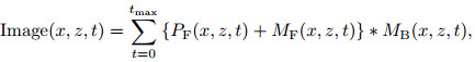
2.2 Imaging Conditions of Reverse Time Migration of MultiplesTypically, imaging conditions of the reverse time migration of multiples can be expressed as follows:
|
(1) |
where tmax is the time length of the records; Image(x, z, t) is the imaging value at location (x, z) at time t; PF (x, z, t) and MF(x, z, t) are respectively the forward wave fields of primaries and multiples at location (x, z) at time t; MB(x, z, t) is the backward wave field of multiples at location (x, z) at time t. Notably, both MF(x, z, t) and MB(x, z, t) contain several orders:

|
(2) |

|
(3) |
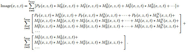
In Eq.(2) and (3), all the items respectively represent the multiples at different order in the forward and backward wave fields, which are substituted into Eq.(1) and the result is developed as follows:
|
(4) |
Each item in Eq.(4) is analyzed in detail as follows:
(1) Every row of the first item successively represents the cross-correlation imaging value of the Nth-order (N≥0) multiples forward wave field (here primaries are considered as the 0th-order multiples, and the same below) and the (N +1)th-order multiples backward wave field. Its calculation result is the correct part of reverse time migration of multiples for imaging, according to the analysis in Section 2.1.
(2) Every row of the second item successively represents the cross-correlation imaging value of the Nthorder multiples forward wave field and the (N + i)th-order (i > 1) multiples backward wave field. Here the first term of the first row is selected for analysis.
The first term of the first row is the cross-correlation imaging value of the primaries forward wave field and the 2nd-order multiples backward wave field. The multiples imaging is illustrated in Fig. 2. In Fig. 2, the ray SRPPRM1M1RM2M2RM3M3 represents the propagation path of a seismic wave, where S represents the seismic source; P, M1, M2 and M3 are respectively the receiver points of records of the primaries, the 1st-order, the 2nd-order and the 3rd-order multiples; RP, RM1, RM2 and RM3 are the subsurface reflection points of these four records. When the primaries records at point P are extrapolated forward, partial energy will be transmitted to the below media as the transmitted wave. When the 2nd-order multiples records at point M2 are extrapolated backward, partial energy will also be transmitted to the below media as transmitted wave. The transmitted wave fields in two time directions will be imaged at point O (the location of point O is related to the model) according to the imaging condition. But actually there is no reflecting interface, so the image at point O is a crosstalk artifact. Similarly, the cross-correlations of the primaries forward wave field with the backward wave fields of (N + j)th-order (j > 2) multiples in the first row will all produce the crosstalk artifacts. By analogy, the remaining rows of the second item all can form the crosstalk artifacts.

|
Fig. 2 Illustration of the imaging of the primaries and the 2nd-order multiples |
(3) Every row of the third item successively represents the cross-correlation imaging value of the Ith-order (I≥1) multiples forward wave field and the Lth-order (1≤L≤I) multiples backward wave field. Firstly the first term of the first row is selected for analysis.
The first term of the first row represents the computed cross-correlation result of the forward and backward wave fields of the 1st-order multiples. The propagation path of multiples is shown in Fig. 3. In Fig. 3, S is the seismic source, P and M are respectively the receiver points of the 1st-order multiples records under the disturbances of forward and backward wave field. Suppose the offsets SP and SM are x1 and x2, and the travel time of the 1st-order multiples received is t1 and t2, respectively. Then discussion is conducted in the following two scenarios:

|
Fig. 3 Illustration of propagation path of the 1st-order multiples |
① If the points P and M coincide, then x1=x2 and t1=t2, and the disturbances of forward and backward wave fields come from the same receiving trace. When the wave field is forward extrapolated, the disturbance of the 1st-order multiples does not occur until the time t1. That is, there will be the wave field value correlated with the 1st-order multiples records in the forward wave field only when t > t1. When the wave field is backward extrapolated in time, the disturbance of the 1st-order multiples does not occur until the time t2. That is, in the backward wave field, there will be the wave field value correlated with the 1st-order multiples records only when t < t2. Therefore, when the points P and M coincide, the forward and backward wave fields of the 1st-order multiples do not “meet” in time axis, and the forward and backward wave fields of the 1st-order multiples cannot be imaged.
② If the points P and M do not coincide, for multiples with the complex structure such as those formed by slant interfaces or diffraction points, there may occur the situation of t1 > t2. But apparently, in this situation the forward and backward wave fields of the 1st-order multiples will not “meet” in time axis. Thus, the forward and backward wave fields of the 1st-order multiples cannot be imaged. However, when t1 < t2, the forward wave field MF1 of the 1st-order multiples at point P will meet the backward wave field MB1 at point M of the 1st-order multiples in time axis. Under this condition, if the velocity model is suitable, the forward wave field at point P and the backward wave field at point M have the possibility of meeting at a certain point in the period of t2 − t1. Thus the forward wave field from point P and the backward wave field from point M can be imaged. But the imaging values of the forward wave field from point P and the backward wave field from point M have no correlations with those of other receivers at the same shot and of the receivers of other shots. Hence the imaging result of the forward and backward wave fields of the 1st-order multiples is difficult to appear in the final profile, but manifests as the background interference.
The remaining rows of the third item represent the cross-correlation values of Kth-order (K≥2) multiples forward wave field and Gth-order (1≥G≤K) multiples backward wave field. These wave fields may also possess the imaging condition, but their imaging values are mainly embodied as the noise.
Notably, the above analyses focus on primaries and multiples from the same reflecting interface, while those from different interfaces may also generate the crosstalk. But the ultimate formation of crosstalk is related to the model selected, which is not discussed here.
3 REVERSE TIME MIGRATION OF DIVIDED-ORDER MULTIPLESAccording to the analysis of Section 2, the data can be correctly imaged only when the Nth-order multiples and (N + 1)th-order multiples of the seismic records are cross-correlated. So the strategy of reverse time migration of multiple at different order is proposed to suppress the cross talk artifacts. Its detailed implementation steps are as follows:
(1) Based on the original shot gather records, multiples are removed by means of SRME to obtain the records only containing primaries.
(2) Based on primaries records, the 1st-order multiples are predicted using feedback loop theory. Then the 2nd-order multiples are predicted using the 1st-order multiples. By analogy, the Nth-order multiples are predicted.
(3) Using the 0th-order and 1st-order multiples respectively as the disturbances of forward and backward wave fields, reverse time migration is computed to obtain the imaging profile of reverse time migration of the 1st-order multiples.
(4) Replacing the 0th-order and 1st-order multiples respectively with the (k-1)th-order (2≤k≤n) and kth-order multiples, step (3) is repeated until k=N. Thus the imaging profiles of multiples of all orders can be obtained (the flow chart of reverse time migration of divided-order multiples is shown in Fig. 4).

|
Fig. 4 The flow chart of RTM of divided-order multiples |
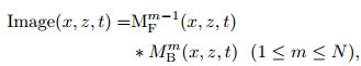
In the strategy proposed, the imaging condition for multiples of each order can be expressed as follows:
|
(5) |
where m is the order of multiples. It is known from Eq.(5) that, the imaging results of the multiples at each order from the same interface only have the real interface but no crosstalk artifact.
4 IMAGING EFFECT OF THE REVERSE TIME MIGRATION OF DIVIDED-ORDER MULTIPLES 4.1 Horizontal Layered ModelHorizontal layered model is established as shown in Fig. 5. The velocity of the first layer is 1800 m·s−1 to the depth of 500 m, and the velocity of the second layer is 2500 m·s−1. The model has a horizontal length of 4000 m, with the total depth of 3000 m. The model uses the single-side observation system with shots on the right and receivers on the left. There are 501 shots, with 301 traces each. The intervals of both shots and traces are 5 m. The depth of receiver is 5 m.

|
Fig. 5 The horizontal layer velocity model |
The research first simulates a set of original shot gather data (including primaries and all-order multiples) based on the model. Then the full multiples records are predicted based on original shot gathers by means of SRME. In order to conduct the reverse time migrations of divided-order multiples, the primaries records are produced through removing the multiples in original shot gathers by means of SRME (The original data of shot gathers, full multiples records and primaries records of No.301 shot are shown in Fig. 6). Subsequently based on the primaries records, the 1st-order, 2nd-order, 3rd-order and 4th-order multiples records are successively predicted (the multiples records at different order at the No.301 shot are shown in Fig. 7).

|
Fig. 6 The 301st shot records (a) Original record including the primaries and multiples; (b) Whole multiples records; (c) Primaries records. |

|
Fig. 7 The 301st multiples records (a) The 1st-order multiples records; (b) The 2nd-order multiples records; (c) The 3rd-order multiples records; (d) The 4th-order multiples records. |
The result of imaging of reverse time migration of multiples based on horizontal layered model is shown in Fig. 8. In the figure, besides the image of actual interface, there are three layers artifacts due to the crosstalk noise. Through analysis, it can be known that the crosstalk artifact 1 comes from three imaging sources: the first one from the imaging with the forward disturbance of the 0th-order multiples (primaries) and the backward disturbance of the 2nd-order multiples, the second one from the imaging with the forward disturbance of the 1st-order multiples and the backward disturbance of the 3rd-order multiples, and the third one from the imaging with the forward disturbance of the 2nd-order multiples and the backward disturbance of the 4th-order multiples. The crosstalk artifact 2 comes from two sources: imaging of the forward disturbance of the 0th-order multiples (primaries) and the backward disturbance of the 3rd-order multiples, and imaging of the forward disturbance of the 1st-order multiples and the backward disturbance of the 4th-order multiples. The crosstalk artifact 3 is the image of the forward disturbance of the 0th-order multiples (primaries) and the backward disturbance of the 4th-order multiples.

|
Fig. 8 The section of RTM of multiples |
The imaging result of reverse time migrations of divided-order multiples is shown in Fig. 9. Comparing Fig. 8 with Fig. 9, it can be known that the imaging profile of multiples at each order can accurately reflect the information of interface. It proves that the strategy of reverse time migrations of divided-order multiples has effectively eliminated the crosstalk of primaries and multiples from the same interface.

|
Fig. 9 The section of RTM of divided-order multiples (a) Imaging section of the 1st-order multiples; (b) Imaging section of the 2nd-order multiples; (c) Imaging section of the 3rd-order multiples; (d) Imaging section of the 4th-order multiples. |
Sigsbee2B model (Fig. 10) is the international standard model for processing seismic multiples data. The model has a horizontal length of 24386 m and a vertical depth of 9144 m, with grid spacing of 7.62 m both horizontally and vertically. The model comprises an undulating seabed interface and steep salt dome.

|
Fig. 10 The Sigsbee2B velocity model |
The data of Sigsbee2B model contain 496 shots with a shot interval of 45.72 m. The number of traces for each shot is variable, with the largest value of 348, corresponding to an interval of 22.86 m. The records time is 12 s and the sample rate is 8 ms. In the research, using the model data containing primaries and multiples as the original shot gather records, the primaries records are derived by removing the multiples in original records with SRME method (original shot gather records and the primaries records of No.226 shot are shown in Fig. 11). Then the full multiples records are predicted based on the original shot gather records (including the multiples of all orders). The 1st-order and 2nd-order multiples records are successively predicted based on the shot gather records of primaries (the full multiples records, the 1st-order and 2nd-order multiples records of No.226 shot are shown in Fig. 12, in which the actual observation time of the first two records is 24 s, but here we only show the records within 16 s; besides, only 18 s of the records of the 2nd-order multiples is presented in spite of the actual observation time of 36 s).

|
Fig. 11 The 226th shot records (a) Original shot records including the primaries and multiples; (b) Primaries records. |

|
Fig. 12 The 226th multiples records (a) The whole multiples records; (b) The 1st-order multiples records; (c) The 2nd-order multiples records. |
From Fig. 11, it can be seen that after the multiples elimination by SRME, the multiples in the original shot gathers are effectively suppressed (indicated by the arrow in Fig. 11a). From Fig. 12, it is known that the predicted multiples based on primaries are mainly the 1st-order multiples, while the full multiples records predicted based on original shot gathers obviously contain the information of the 2nd-order and 3rd-order multiples (indicated by the arrow in Fig. 12a). Hence, the reverse time migration of multiples based on full multiples records will produce relatively strong crosstalk artifacts.
Figure 13 shows the imaging profile of conventional reverse time migration of multiples, which takes the original shot gather records as forward disturbance and full multiples records as backward disturbance, as well as the imaging profiles of reverse time migration of the 1st-order and 2nd-order multiples.

|
Fig. 13 The sections of RTM of multiples (a) Imaging section of common RTM of multiples; (b) Imaging section of the 1st-order multiples; (c) Imaging section of the 2nd-order multiples. |
From Fig. 13, it can be seen that there are apparent crosstalk artifacts in the conventional imaging profile (indicated by the arrow in Fig. 13a), which greatly reduce the accuracy and credibility of imaging. However, the imaging profiles of the 1st-order and 2nd-order multiples, based on the strategy of reverse time migration of divided-order multiples, have no evident crosstalk noise. In order to further analyze the precision of imaging, the imaging profile circled by the rectangle in Fig. 13 is magnified for comparison. The magnified graph of the velocity model corresponding to the rectangular area is shown in Fig. 14, and the magnified graphs of each profile are shown in Fig. 15.

|
Fig. 14 Magnified view of the velocity model in the rectangular window |

|
Fig. 15 Magnified views of the sections in the rectangular window (a) Section of the common RTM of multiples; (b) Section of the 1st-order multiples; (c) Section of the 2nd-order multiples. |
From Fig. 15, it is known that the deep structure is blurring and precision of imaging is low in the imaging profiles of conventional reverse time migration of multiples. Comparatively, the precision of deep imaging is apparently improved by using the strategy of reverse time migrations of divided-order multiples. It verifies the effectiveness of the strategy to suppress the crosstalk artifacts. But meanwhile, we find the low precision of the deep imaging by reverse time migration of the 2nd-order multiples. It is caused by the residue of multiples in the primaries reflection records. Another cause is that the primaries endure some loss in the process of removing the multiples. Due to this effect, a higher order of multiples leads to a lower precision of prediction. At the same time, due to the longer propagation path of higher-order multiples than that of the 1st-order multiples, the precision of prediction and energy of the 2nd-order multiples are lower than those of the 1st-order multiples. This also leads to the lower precision of imaging of the 2nd-order multiples than the 1st-order multiples.
5 CONCLUSIONS AND PROSPECTSOn the basis of in-depth analysis of the principle of multiples imaging and the mechanism of crosstalk artifact, the research raises and realizes the strategy of reverse time migrations of divided-order multiples. The model experiments indicate that the imaging profiles of multiples at each order all can effectively depict the actual reflecting interface and avoid the crosstalk of uncorrelated multiples from the same interface. As for the complicated model structure, the imaging profile obtained by the reverse time migration of the 1storder multiples, i.e., adopting the strategy of dividing the order of multiples, can significantly decrease the interference of crosstalk. Accordingly, the quality of deep imaging by reverse time migration of multiples is greatly improved, which manifests a good prospect for application of reverse time migrations of divided-order multiples for imaging.
Undoubtedly, the proposed strategy of reverse time migration of divided-order multiples is still confronted with the low computational efficiency and a low accuracy of imaging when using higher-order multiples. And the strategy only applies to suppressing the crosstalk artifact of multiples from the same reflecting interface. However, with wide application of GPU cluster in the geophysical community and with the help of strong parallel computing capacity of GPU cluster, the computational efficiency of reverse time migration of multiples will be significantly improved. In the experiment of reverse time migration of multiples based on four Tesla K20 GPUs, the computing time of the reverse time migration in Sigsbee2B model is only about 3 hours. With the gradual popularity of the large GPU cluster, the treatment of reverse time migration of multiples based on real data will come true. Therefore, the future work is to increase the precision of multiples-based prediction and imaging, further suppress the crosstalk of multiples imaging, and improve the imaging precision at each order of multiples, especially at the higher order.
ACKNOWLEDGMENTSThis work was supported by the Fundamental Research Funds for the Central Universities (201513005) and the National Natural Science Foundation of China (41574105)
| [] | Berkhout A J, Verschuur D J. 2006. Imaging of multiple reflections. Geophysics , 71 (4) : SI209-SI220. DOI:10.1190/1.2215359 |
| [] | Brown M P, Guitton A. 2005. Least-squares joint imaging of multiples and primaries. Geophysics , 70 (5) : S79-S89. DOI:10.1190/1.2052471 |
| [] | Guitton A. 2002. Shot-profile migration of multiple reflections.//SEG Technical Program Expanded Abstracts. SEG, 1296-1299, doi:10.1190/1.1816892. |
| [] | Guo S J, Li Z C, Tong Z Q, et al. 2011. Joint imaging of primaries and surface-related multiples based on generalized shot-profile migration. Chinese J. Geophys. (in Chinese) , 54 (4) : 1098-1105. DOI:10.3969/j.issn.0001-5733.2011.04.025 |
| [] | Guo S J, Li Z C, Tong Z Q, et al. 2012. Method and technique for imaging of surface-related multiples. Progress in Geophysics (in Chinese) , 27 (6) : 2570-2576. DOI:10.6038/j.issn.1004-2903.2012.06.034 |
| [] | He R Q, Hornby B, Schuster G T, et al. 2007. 3D wave-equation interferometric migration of VSP free-surface multiples. Geophysics , 72 (5) : S195-S203. DOI:10.1190/1.2743375 |
| [] | Jiang Z Y, Yu J H, Schuster G T, et al. 2005. Migration of multiples. The Leading Edge , 24 (3) : 315-318. DOI:10.1190/1.1895318 |
| [] | Jiang Z Y, Sheng J M, Yu J H, et al. 2007. Migration methods for imaging different-order multiples. Geophysical Prospecting , 55 (1) : 1-19. DOI:10.1111/j.1365-2478.2006.00598.x |
| [] | Liu Y K, Chang X. 2011. Reverse time migration of multiples.//81st Ann. Internat. Mtg., Soc. Expl. Geophys. Expanded Abstracts. San Antonio, 3326-3331. |
| [] | Liu Y K, Chang X, Jin D G, et al. 2011. Reverse time migration of multiples for subsalt imaging. Geophysics , 76 (5) : WB209-WB216. DOI:10.1190/geo2010-0312.1 |
| [] | Liu Y K, Zhu W L, Mi L J, et al. 2015. Migration of multiples from the South China Sea. Science China Earth Sciences , 58 (3) : 482-490. DOI:10.1007/s11430-014-4952-y |
| [] | Muijs R, Robertsson A J O, Holliger K. 2005. Prestack depth migration of primary and surface-related multiple reflections:Part I-Imaging. Geophysics , 72 (2) : S59-S69. DOI:10.1190/1.2422796 |
| [] | Reiter E C, Toksz M N, Keho T H, et al. 1991. Imaging with deep-water multiples. Geophysics , 56 (7) : 1081-1086. DOI:10.1190/1.1443119 |
| [] | Shan G J. 2007. Surface-related multiple migration. Geophysical Prospecting for Petroleum (in Chinese) , 46 (6) : 604-610. |
| [] | Sheng J M. 2001. Migrating multiples and primaries in CDP data by crosscorrelation migration.//71st Ann. Internat. Mtg., SEG Technical Program Expanded Abstracts. SEG, 1297-1300, doi:10.1190/1.1816333. |
| [] | Vasconcelos I, Snieder R, Hornby B. 2008. Imaging internal multiples from subsalt VSP dataExamples of target-oriented interferometry. Geophysics , 73 (4) : S157-S168. DOI:10.1190/1.2944168 |
| [] | Verschuur D J, Berkhout A J. 2005. Transforming multiples into primaries:Experience with field data.//Expanded Abstracts of the 75th Annual Meeting of the Society of Exploration Geophysicists. 2103-2106, doi:10.1190/1.2148127. |
| [] | Wang Y B, Chang X, Hu H. 2014. Simultaneous reverse time migration of primaries and free-surface related multiples without multiple prediction. Geophysics , 79 (1) : S1-S9. DOI:10.1190/geo2012-0450.1 |
| [] | Ye Y M, Zhao C L, Zhuang X J, et al. 2014. Migration of surface correlated multiples based on one-way wave equation. Chinese J. Geophys. (in Chinese) , 57 (4) : 1241-1250. DOI:10.6038/cjg20140421 |
| [] | Yu J H, Schuster G T. 2002. Joint migration of primary and multiple reflections in RVSP data.//72nd Ann. Internat. Mtg, Soc. Expl. Geophys., Expanded Abstracts. 2373-2376, doi:10.1190/1.1817193. |
| [] | Zhang D L, Schuster G T. 2014. Least-squares reverse time migration of multiples. Geophysics , 79 (1) : S11-S21. DOI:10.1190/geo2013-0156.1 |
| [] | Zhu B, Song P, Li J S, et al. 2015. Reverse time migration of multiples based on the acceleration of multi-card GPU. Petroleum Geology and Recovery Efficiency (in Chinese) , 22 (2) : 60-65. |