 2013, Vol. 56


There are two types of component-type borehole strainmeters. One is the three-component strainmeter developed abroad (USA, Japan and Australia), in which the 3 measurement components are arranged with a 60° angle between each other. The other is the four-component strainmeter developed in China, whose 4 measurement components have a 45° angle to each other, like the Chinese character “米”. The “Plate Boundary Observation (PBO)”[1] which was started from 2003 in America planned to establish 175 borehole strain stations along the San Andreas Fault and Southern Alaska at American west coast. Up to now, 85 new Gladwin component strainmeters[2] have been installed and put into operation. Affected by the American PBO Plan, research and applications of the Chinese four-component strainmeter have developed rapidly during the Tenth Five-Year period. The YRY-4 strainmeter[3], which is developed by Chi Shun-Liang, has been applied to key earthquake monitoring areas in China (including more than 40 survey points) and obtained observation data of five consecutive years. The RZB-2 and RZB-3 strainmeters[4, 5] which are developed by Ouyang Zu-Xi, have been used in earthquake observations in Xinjiang, Gansu, Sichuan and Chongqing. Now there are 12 sets of the instruments are running, and there will be much more in the Twelfth Five-Year period. Apparently, component strainmeters are gradually becoming the mainstream instrument in crustal strain field observation in the world[6]. No matter what type of component strainmeter it is, the working principle remains the same. All the gauges utilize the radial displacement sensor to measure relative change of the borehole diameter in rocks. The senso has to be fixed on the underground bedrock (tens to hundreds of meters deep) with expansive cement (or cement). Therefore, the rock, cement and instrument steel tube form a three-layer composite double-bush structure. Significant coupling effects are inevitable due to concentrated wellhole stress and stress transfer in each medium layer. As can be seen from theoretical formulas[7, 8], all the linear strain measured by each component has two coupling coefficients (A, B). Compared with the traditional body strainmeter (blind direction), the component strainmeter has a prominent progress in functions. It can determine the maximum principal strain, minimum principal strain and direction of the maximum principal strain of the crustal strain field between two moments based on any measured strain values in three directions. But the prerequisite is to know in advance the two coupling coefficients, otherwise this function does not make any sense. So solving these two coupling coefficients is a crucial basic problem. At present, there are two methods to solve this problem in the world: inversion and forward modeling. For inversion, the method proposed by Hart et al.[9] utilizes the average earth tide measured by baseline laser strainmeters (1~2 km long) to demarcate the three-component strainmeter; Roeloffs[2] carried out harmonic analysis on strain observation values to obtain the coupling coefficients. In China, Qiu Z H et al.[7] used the relationship between observed earth tide and theoretical earth tide to invert the coupling coefficients. The forward modeling belongs to traditional methods; Gladwin et al.[10] established a dual-ring model to utilize complex variable functions to obtain results. Luo M J et al.[11] derived a two-layer medium model (rock, steel tube) for solving the coupling coefficient formulas. Different from the above-mentioned work, this paper proposes a new idea. Based on the research of Pan L Z[12], Ouyang Z X[13] and Chen Y J[14], we select a double bush model which is close to the actual situation to derive the final theoretical calculation formulas of the two coupling coefficients. This method has a positive meaning for the borehole strain observational study. It can also combine with calculation results of other methods in terms of reliability analysis to play a greater role in monitoring of earthquakes, volcanoes and plate boundaries.
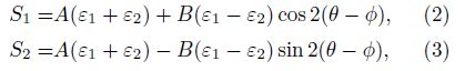
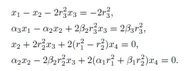
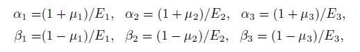
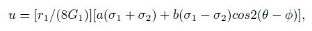
2 THEORETICAL MODEL OF COMPONENT STRAINMETER OBSERVATIONWe assume that there is an infinitely large rock plate, at infinity which withstands two uniform horizontal tensile stress, i.e, the maximum and minimum stress σ1 and σ2, with the maximum and minimum strain ε1 and ε2. In the plate, there is a wellhole with a radius r3, in which a strainmeter steel tube with inner-radius r1 and outer radius r2 is fixed. The steel tube is fixed on the rock with expansive cement (welding) to ensure the continuity of stress and displacement components on the boundary. Therefore, the borehole has a three-layer composite double-bush structure (Fig.1). Let E1, μ1, E2, μ2, E3, and μ3 be the elastic modulus and Poisson’s ratios of steel tube, cement and rock, respectively. We assume that the medium in which the borehole is located is an isotropic elastic medium, and the effect of wellhead and well bottom on the sensor can be ignored according to Hooke’s law. So the axial stress of the borehole is 0. Let θ be the angle between the north direction and any component measuring the relative change of borehole, $\phi $ be the angle between the north direction and the maximum principal stress. We specify that, starting from the north direction, the value of the angle which is rotated clockwise is positive and the value of the angle which is rotated counterclockwise is negative. And the radial strain on the steel tube wall in the θ direction is[7]


|
Fig.1 Double bushing model of borehole strain observation |
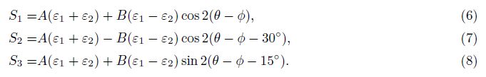
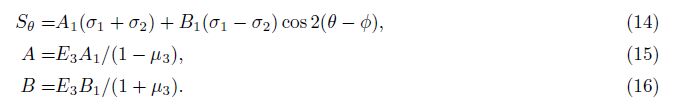
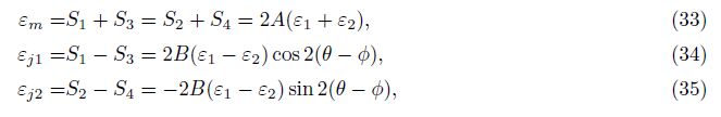
For the four-component borehole strainmeter, starting from the north direction to right, if the angle of the first component is θ, then the angle of the second, third and fourth component will increase 45° successively. That is, components one and three are perpendicular to component two and four, respectively. The strain values of the four components can be written as

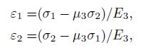
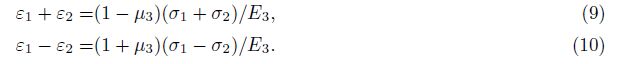
Under the effect of plane stress, the linear strain of non-porous rock is

In 1981, Pan L Z[12] proposed the principle of measuring crustal stress with the borehole lining method and derived related basic formulas. And he gave a particular solution table for solving elastic plane problems. In 1988, Ouyang Z X and Zhang Z R analyzed the boundary conditions and interface conditions of the double-bush borehole, obtained the particular solutions according to Pan’s particular solution, and proposed three linear equations with unknown constants to be determined and the formula of radial displacement on the inner wall of probe steel tube[13]. In 1990, Chen Y J et al.[14] further calculated these unknown constants and derived expressions of radial strain on the inner wall of the steel tube in θ direction:

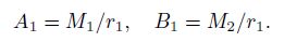
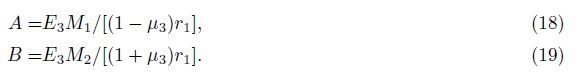
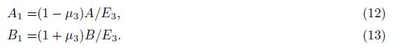
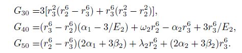
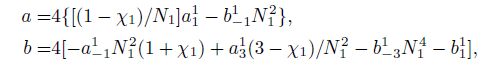
Based on the work of Pan, Ouyang, Zhang and Chen et al. aforementioned, we know that both M1 and M2 are constants related to elastic parameters and radius of layers of material[14], where there is


It should be noted that the use of thick-walled cylinder equation[15] can also derive exactly the same formulas mentioned above (this will be further explained in another dedicated essay), which indicates that the research work of Pan et al. is reliable.
Besides, there is[14]

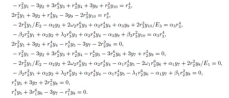
Then we obtain the expressions of y1, y2, y3, y4, y9 and y10 and substitute them into (II). The results show that the derivation of calculation formula of y5, y6, y7 and y8 is correct.
4 COMPARISON WITH GLADWIN’S RESULTS 4.1 The Focus of ComparisonIn 1981, Pan[12] had considered using functions of complex variables when establishing the double-bush model, and he thought it was a powerful tool for solving elastic plane problems. However, the polar coordinates solution method was finally selected because some practitioners were not familiar with functions of complex variables which not convenient for them (in fact, this research has begun to take shape early in 19771) ( 1) Pan L Z. Derivation and discussion of several formulas about measurement of earth stress. Selected Papers of National Professional Meetings of Earth Stress (first volume), National Professional Meetings of Earth Stress of State Seismological Bureau, 1977: 1-41.)). In 1985, Gladwin et al.[10] established a double-ring observation model, i.e. the instrument steel tube is the first ring and the expansive cement is the second ring. The principle of this method is basically the same as that of the double-bush model, but it utilizes functions of complex variables to solve the two coefficients. Under the effect of plane stress, the radial strain of the probe steel tube is[10]


Gladwin et al.[10] also proposed conceptions of the area strain response factor c and shear strain response factor d


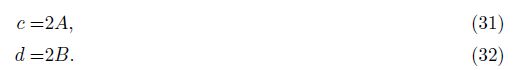
It is not difficult to derive the following equations based on formulas (2), (3), (4) and (5),
For non-porous rock, assuming that there is a cylinder in rock, the radial strain in the θ direction is[17]

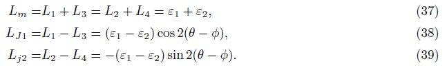
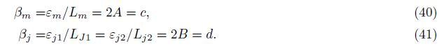
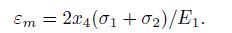
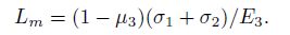
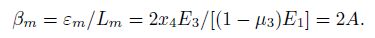
For the three-component strainmeter, (40) and (41) also hold. This is because the area strain εm recorded by the strainmeter has nothing to do the number of components, and theoretically[18]
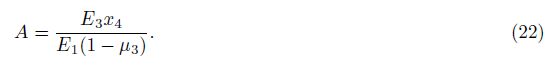
Gladwin[10] provided the relation curve of area strain response factor (c) and shear modulus ratio (Fig.2a). According to his idea, if we set G2/G1 = G21, G3/G1 = G31, substituting Ei = 2(1 + μi)Gi(i = 1, 2, 3) into formulas (21) and (22), and taking[8] G1 = 8.39×10¹⁰ Pa, μ1 = 0.283, μ3 = 0.25, r1=56 mm, r2=62 mm, r3=89 mm, then we have

Mimicing Fig.2a, we make the relation curve (Fig.2b) of 2A and shear modulus ratio (G2/G1) and keep them in the same scale. Then we can use drawing software in Windows to make transparency processing and overlap (a) and (b). It can be seen that the two graphical curves are almost completely consistent with each other, fully indicating that 2A = c holds.

|
Fig.2 Comparison of 2A and c curves (a) The relationship curve between area strain response factor (c) and shear modulus ratio ( G2/G1) (according to Ref. [10] Fig.6); (b) The relationship curve between two times of coupling coefficient (2A) and shear modulus ratio (G2/G1) (The results in this paper) G1, G2, G3 each said strainmeter steel cylinder, expansive cement and rock shear modulus. |
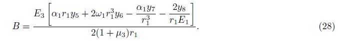
Gladwin[10] also provided the relation curve of shear strain response factor (d) and shear modulus ratio (Fig.3a). According to his idea, (28) can be transformed into


Similarly, mimicing Fig.3a, we make the relation curve (Fig.3b) of 2B and shear modulus ratio (G2/G1) and keep them in the same scale. Then we can use drawing software in Windows to make transparency processing and overlap (a) and (b). It can be seen that the two graphical curves are almost completely consistent with each other, fully indicating that 2B = d holds.

|
Fig.3 Comparison of 2B and d curves (a) The relationship curve between shear strain response factor (d) and shear modulus ratio (G2/G1) (according to Ref. [10] Fig.7); (b) The relationship curve between two times of coupling coefficient (2B) and shear modulus ratio (G2/G1) (The results in this paper). G1, G2, G3 are each said strainmeter steel cylinder, expansive cement and rock shear modulus. |
The above analysis shows that the present results are identical with Gladwin’s results. The correctness of the two methods is thereby proved by each other, the formulas derived in this paper can obtain the same graphics as that of Gladwins et al.[10].
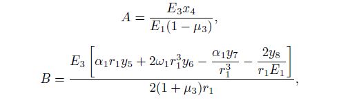
5 CONCLUSIONS AND DISCUSSION(1) With plane stress, the two coupling coefficients of component borehole strain observation can be respectively expressed as
(2) The change characteristic of the coupling coefficient A is: when G2/G1 < 0.1, A increases rapidly with the increase of G2/G1 and decreases slowly with the decrease of G2/G1. The change characteristic of the coupling coefficient B is: when G2/G1 < 0.01, B increases rapidly with the minor increase of G2/G1 and decreases with the decrease of G2/G1, and when 0.01 < G2/G1 < 0.2, it decreases rapidly with the decrease of G2/G1; but when G2/G1 > 0.2, it decreases slowly with the decrease of G2/G1. The common characteristics of A and B are: when G2/G1 is a fixed value, A and B increase with the increase of G3/G1; and when G2/G1, G3/G1, μ1 and μ3 are fixed values, the change of μ2 has very small impact on both of them.
(3) It should be noted that for a real nonporous rock, A = B = 1/2; for rock with pores, A = 1/(1-μ3), B = 2/(1+μ3), if we take μ3 = 0.25, then A = 1.333, B = 1.600. For borehole strain observation systems, generally A and B are not exactly 1/2 and not simultaneously 1.333 and 1.600. Therefore the radial strain on the inner wall of steel tube is not equal to the linear strain of non-porous rock in the same direction, nor the radial strain on the inner wall of rock with pores in the same direction. And the recorded earth tide and theoretical strain earth tide along the same line are not a paired comparison relationship.
(4) How to measure and calculate the two parameters A and B indoors is the task that needs to be carried out immediately. Elasticity modulus of rock and Poisson’s ratio are indispensable for theoretical calculations. Therefore, we need to carry out sampling tests of rock cores around the sensor, and this sample work is very important foundation work. However, most stations have not done this yet. As time goes some stations will lose some information of cores and their information storage will be incomplete. So from now on we must establish this kind of projects to promote the foundation work.
ACKNOWLEDGMENTSWe are grateful to Su K Z and Qiu Z H for their constructive support and help in the research, and three anonymous reviewers for their pertinent amendment suggestions. This work was supported by the National Science and Technology Support Planning Program (2012BAK19B02-02) and Seismic Industry Special Research (201108009).
| [1] Zhang B H. Plate boundary observation (PBO) project of USA. Journal of Geodesy and Geodynamics (in Chinese), 2004, 24(3): 105-108. |
| [2] Roeloffs E. Tidal calibration of plate boundary obervatory borehole strainmeters: roles of vertical and shear coupling. J. Geophys. Res., 2010, 115(B6), B06405, doi:10.1029/2009JB006407. |
| [3] China Seismological Bureau Monitoring and Prediction Department. Ground Department Measurement (in Chinese). Beijing: Earthquake Press, 2008. |
| [4] Ouyang Z X, Zhang Z R, Shu G L. Review and outlook for west china borehole strainmeter networks. Chinese Journal of Rock Mechanics and Engineering (in Chinese), 2004, 23(23): 4058-4062. |
| [5] Ouyang Z X, Zhang J, Chen Z, et al. New progress in multi-compenent observation of crustal deformation in deep boreholes. Recent Developments in World Seismology (in Chinese), 2009, (11): 1-13. |
| [6] Qiu Z H. A review of component borehole observation of stress-strain in China. Journal of Geodesy and Geodynamics (in Chinese), 2010, 30(5): 42-47. |
| [7] Qiu Z H, Shi Y L, Ouyang Z X. Absolute calibration of 4-component borehole strainmeters. Earthquake (in Chinese), 2005, 25(3): 27-34. |
| [8] Su K Z. Method of Ground Stress Measurement (in Chinese). Beijing: Earthquake Press, 1985. |
| [9] Hart R H G, Gladwin M T, Gwyther R L, et al. Tidal calibration of borehole strain metrics: Removing the effects of small-scale inhomogeneity. J. Geophys. Res., 1996, 101(B11): 25553-25571. |
| [10] Gladwin M T, Hart R. Design parameters for borehole strain instrumentation. Pure Appl. Geophys., 1985, 123(1): 59-80. |
| [11] Luo M J, Gu M L, Li A Y, et al. Borehole strain-stress calibration in the same place by use of tidal generation force. Crustal Deformation and Earthquake (in Chinese), 1989, 9(4): 8-62. |
| [12] Pan L Z. On formulas of ground stress measurement//Principles and Application of Ground Stress Measurement (in Chinese). Beijing: Geological Press, 1981. |
| [13] Ouyang Z X, Zhang Z R. Studies of method for coupling straingauge with borehole wall//Crustal Tectonic and Crustal Stress (2) (in Chinese). Beijing: Earthquake Press, 1988. |
| [14] Chen Y J, Yang X X. Calculations of strain observation in the borehole with two cases. North China Earthquake Sciences (in Chinese), 1990, 8(4): 80-89. |
| [15] Yang X L, Jin J S. Elasticity Mechanics (in Chinese). Beijing: Higher Education Press, 1987. |
| [16] Jiang J, Zhang Y B. The physics-mechanical significance of tidal strain combination and its harmonic analysis. Acta Geophysica Sinica (in Chinese), 1994, 37(Suppl.I): 204-212. |
| [17] Wang R. Foundations of Solid Mechanics (in Chinese). Beijing: Geological Press, 1987. |
| [18] Zhang L K, Niu A F, Wu L J. Conversion factors from volume to area strain in crustal strain observation. Acta Seismologica Sinica (in Chinese), 2012, 34(4): 476-486. |