扩展功能
文章信息
- 李凌云, 陈浩, 李少伟, 谢达承, 王强
- LI Ling-yun, CHEN Hao, LI Shao-wei, XIE Da-cheng, WANG Qiang
- 异型钢结构自适应动态吸能阻尼器设计及试验研究
- Design and Experimental Study on Adaptive Dynamic Energy Absorption Damper for Special-shaped Steel Structures
- 公路交通科技, 2021, 38(12): 147-151
- Journal of Highway and Transportation Research and Denelopment, 2021, 38(12): 147-151
- 10.3969/j.issn.1002-0268.2021.12.017
-
文章历史
- 收稿日期: 2021-02-24
2. 北京恒达交安科技发展有限公司, 北京 102200;
3. 中咨华科交通建设技术有限公司, 北京 100089
2. Beijing Hengda Jiao'an Technology Development Co., Ltd., Beijing 102200, China;
3. Zhongzi Huake Transport Construction Technology Co., Ltd., Beijing 100089, China
避险车道一直以来是长大下坡路段行车安全的重要防护手段,现阶段我国长大下坡路段避险车道多采用碎石制动床避险车道,通过制动床的碎石填料增加失控车辆行驶阻力,从而使驶入避险车道的车辆减速直至停车。按照我国现行标准规范要求,碎石避险车道的设置长度主要受失控车辆驶入避险车道时的车速、制动床坡度、车辆滚动摩阻系数的影响,当车速在100 km/h、车辆滚动摩阻系数在0.25、坡度在3°~5°时,一般避险车道的设计长度在120 m以上[1]。然而,避险车道的设置长度受地形条件、环境条件的限制,容易出现设置空间不足、碎石填料板结而摩擦系数降低等现象,从而导致避险车道减速能力下降。
近年来,通过增加辅助减速措施提升避险车道减速效果已在行业内进行了部分研究与尝试[2],但仍存在较大的研究空间,如阻尼器技术突破[3-18]。基于此,本研究提出了一种基于异型钢结构的自适应动态吸能阻尼器,通过优化阻尼器结构来适应不同条件下的阻尼需求,并通过模型试验对其阻尼性能进行研究,在提高阻尼效果的同时,使其结构简单、经济合理,并具有工程可操作性。
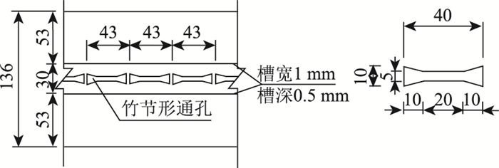
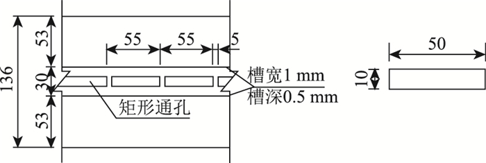
1 动态吸能阻尼器设计动态吸能阻尼器由吸能板和切割轴组成,其工作原理为:当失控车辆输入避险车道时,车体通过钢丝绳带动避险车道阻尼器中的切割轴滑动,通过切割轴的滑动使吸能板吸能孔撕裂,从而达到吸能的效果。为了研究不同吸能孔对动态吸能效果的影响,本研究采用20 mm厚Q235钢板为基础材料,设计了2种异性钢结构的阻尼器,一种为竹节形阻尼器,见图 1;另一种为矩形阻尼器,见图 2。其中,竹节形阻尼器每个吸能孔长度为40 mm,按照间距3 mm均布;矩形阻尼器每个吸能孔50 mm,按照间距5 mm均布。
|
| 图 1 竹节形阻尼器结构示意图(单位: mm) Fig. 1 Schematic diagram of slubby damper structure(unit: mm) |
| |
|
| 图 2 矩形尼器结构示意图(单位: mm) Fig. 2 Schematic diagram of rectangular damper structure(unit: mm) |
| |
2 模型试验分析 2.1 试验方案
本研究以车重50 t、运行速度为100 km/h的失控车辆作为防护目标,阻尼器沿避险车道制动床双侧布设,则单侧阻尼器需提供的吸能阻力约为125 kN。本试验中,阻尼器中安装4片吸能板,每片长度6 m,吸能板材质为3 mm厚Q235,切割轴材质40cr,ϕ30 mm,采用自重为17 t的装载机以约30 km/h的运行速度对阻尼器的输出阻尼器的大小、吸能板的变形形态和阻尼器的稳定性等进行验证,试验中所用钢丝绳为ϕ30,3×37类纤维芯钢丝绳,钢丝绳抗拉强度1 770 MPa,钢丝绳破断拉力为476 kN,阻尼器模型试验平面图如图 3所示。

|
| 图 3 阻尼器模型试验平面示意图(单位: mm) Fig. 3 Schematic diagram of damper model test(unit: mm) |
| |
2.2 模型试验分析
(1) 竹节形阻尼器试验结果
竹节形阻尼器孔长40 mm,节宽3 mm。试验过程中,吸能板按预定方向变形,变形方向与设定情况一致。本次试验吸能板撕裂长度为3.1 m,其中有效长度为3.0 m。整体试验结果如表 1所示。
| 试验条件测试结果 | 试验车辆 | 车速/(km·h-1) | 车重/t | 车辆动能/kJ | ||
| 50型装载机 | 27 | 16.74 | 470 | |||
| 吸能板类型 | 吸能板片数 | 撕裂长度 | 最大拉力/kN | 平均拉力/kN | 吸能/kJ | |
| 竹节形 | 4 | 3 m | 221.5 | 112.3 | 277.5 | |
| 阻尼器稳定性 | 阻尼器外壳(Q235厚20 mm) | 无变形 | ||||
| 吸能板(Q235厚3 mm) | 向固定方向撕裂变形 | |||||
| 限位板(Q235厚3 mm) | 无破坏 | |||||
| 钢丝绳(ϕ30) | 无破坏 | |||||
| 轴(40Cr ϕ30)(无热处理) | 磨损严重、弯曲变形 | |||||
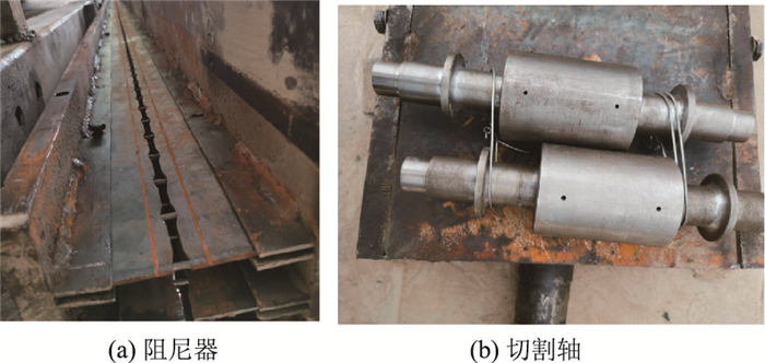
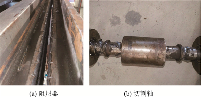
由表 1可知,在上述试验条件下,经与试验前阻尼器(如图 4所示)对比可知,阻尼器外壳无明显变形,切割轴试验后轴磨损严重,有弯曲变形,但整体结构仍较为完好(如图 5所示),试验中钢丝绳无破损,说明竹节形阻尼器结构合理。
|
| 图 4 试验前的竹节形阻尼器 Fig. 4 Slubby damper before test |
| |
|
| 图 5 试验后的竹节形阻尼器 Fig. 5 Slubby damper after test |
| |
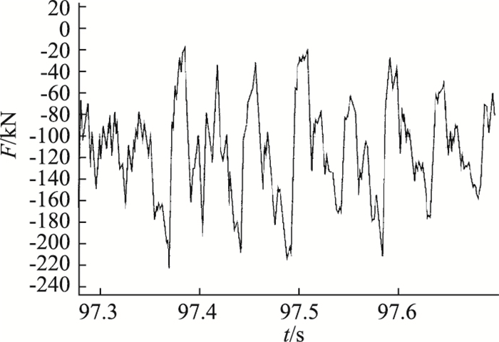
竹节形阻尼器在吸能板过程中,最大拉力为221.5 kN,平均拉力为112.3 kN,破坏时间0.8 s,有效破坏长度为3.0 m,拉力变化图如图 6所示。
|
| 图 6 竹节形阻尼器拉力变化图 Fig. 6 Graph of tension of slubby |
| |
假设试验过程中切割轴做匀减速运动,当阻尼器撕裂长度为3.0 m,用时0.8 s,装载机初始动能Ep为470 kJ时,则竹节形阻尼器的平均吸能阻力可达到112.3 kJ/m,通过调整阻尼器吸能装置组合,可以达到避险车道的防护目标。
(2) 矩形阻尼器试验结果
矩形阻尼器孔长50 mm,节宽5 mm。试验结果表明:吸能板按预定方向变形,变形方向基本与设定情况一致,但起始段变形不规则。本次试验吸能板撕裂长度为2.93 m,其中有效长度为2.83 m。整体试验结果如表 2所示。
| 试验条件测试结果 | 试验车辆 | 车速/(km/h) | 车重/t | 车辆动能/kJ | ||
| 50型装载机 | 22 | 17.56 | 327 | |||
| 吸能板类型 | 吸能板片数 | 吸能板撕裂长度 | 最大拉力/kN | 平均拉力/kN | 吸能/kJ | |
| 矩形 | 4 | 2.83 m | 224.6 | 119.7 | 220.7 | |
| 阻尼器稳定性 | 阻尼器外壳(Q235厚20 mm) | 无变形 | ||||
| 吸能板(Q235厚3 mm) | 向固定方向撕裂变形 | |||||
| 限位板(Q235厚3 mm) | 无破坏 | |||||
| 钢丝绳(ϕ30) | 无破坏 | |||||
| 轴(40Cr ϕ30)(热处理) | 磨损严重、无变形 | |||||
由表 2可知,在上述试验条件下,经与试验前阻尼器(如图 7所示)对比可知,阻尼器外壳无明显变形,吸能孔向着设定方向撕裂变形吸能,切割轴试验后轴磨损严重,但整体结构仍较为完好(如图 8所示),试验中钢丝绳无破损。
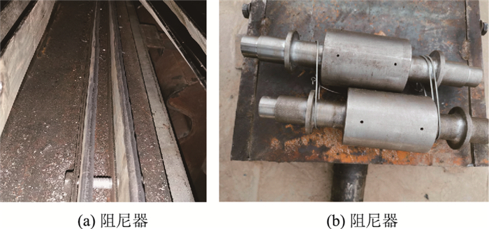
|
| 图 7 试验前的矩形阻尼器 Fig. 7 Rectangular damper before test |
| |
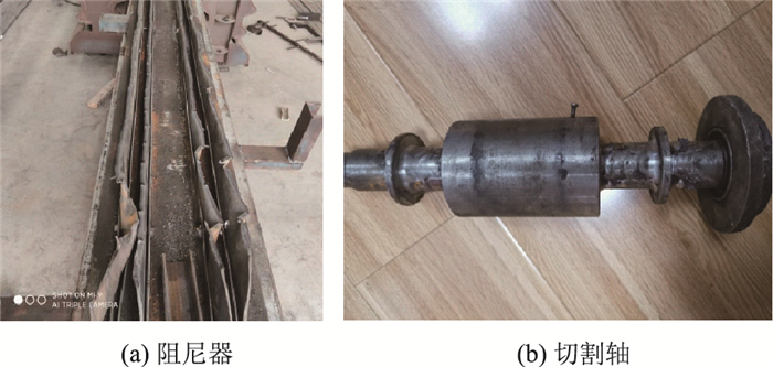
|
| 图 8 试验后的矩形阻尼器 Fig. 8 Rectangular damper after test |
| |
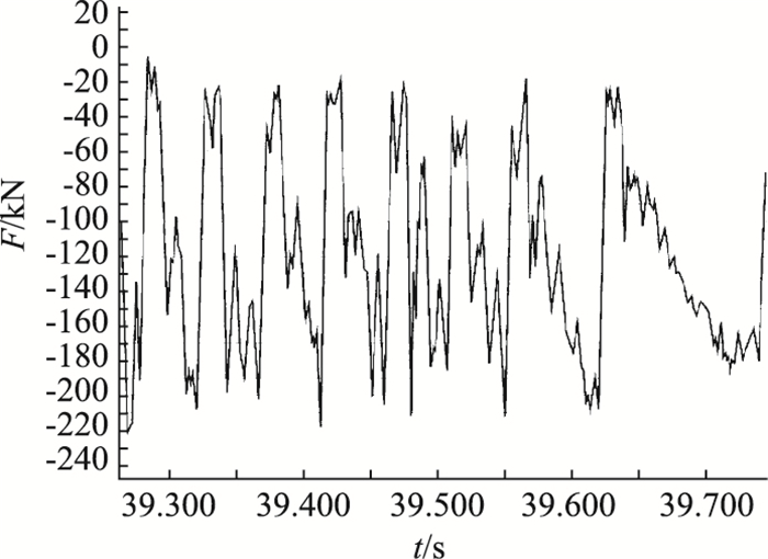
矩形阻尼器在吸能板过程中,最大拉力为224.6 kN,平均拉力为119.7 kN,破坏时间0.9 s,有效破坏长度为2.83 m,拉力变化图如图 9所示。
|
| 图 9 矩形阻尼器拉力变化图 Fig. 9 Graph of tension of rectangular damper |
| |
同竹节形试验假设条件相同,假设试验过程中切割轴做匀减速运动,当阻尼器撕裂长度为2.83 m,用时0.9 s,装载机初始动能Ep为327 kJ时,则矩形阻尼器的平均吸能阻力可达到119.7 kJ/m。通过调整阻尼器吸能装置组合,可以达到避险车道的防护目标。
将试验1与试验2结果进行对比可知,竹节形和矩形阻尼器均具有较好的吸能效果,因此,在实际工程中均可做为阻尼避险车道的吸能装置,可根据实际情况进行选取。
3 结论(1) 竹节形阻尼器及矩形阻尼器在模型试验中整体结构较为稳定,试验中阻尼器外壳用钢板厚度为20 mm,实际工程中可通过增加阻尼器长度或采用槽钢桁架结构来适当降低阻尼器外壳钢板厚度。
(2) 4块竹节孔吸能板阻尼力平均值为112.3 kN,最大值为221.5 kN;4块矩形孔吸能板阻尼力平均值为119.7 kN,最大值为224.6 kN;矩形孔吸能板的平均阻尼力119.7 kN较竹节孔吸能板接近目标阻尼力120 kN,试验中切割轴虽有磨损和变形,但体理结构较为完整,结构合理。
(3) 采用合理的异形钢结构的动态吸能阻尼器能够提供较好的阻尼力,为阻尼避险车道的设计提供基础条件。
(4) 本研究所述的研究成果可以为未来避险车道结构优化提供较好的基础数据,提高避险车道的减速效果,并提升对环境和空间的适用性。
| [1] |
苏何先, 潘文, 兰香, 等. 非线性黏滞阻尼器性能试验[J]. 振动与冲击, 2019, 38(20): 61-69. SU He-xian, PAN Wen, LAN Xiang, et al. A Study on the Performance of Nonlinear Viscous Damper Testing[J]. Journal of Vibration and Shock, 2019, 38(20): 61-69. |
| [2] |
万然, 刘凤贵, 刘德州, 等. 耐高速冲击阻尼器设计与试验研究[J]. 工业仪表与自动化装置, 2020(6): 121-124. WAN Ran, LIU Feng-gui, LIU De-zhou, et al. Design and Experimental Research on High-speed Shock-resistant Damper[J]. Industrial Instrumentation & Automation, 2020(6): 121-124. |
| [3] |
王唯一, 傅磊, 王翔, 等. 避险车道新型阻尼系统研究[J]. 武汉理工大学学报: 交通科学与工程版, 2019, 43(12): 1033-1037. WANG Wei-yi, FU Lei, WANG Xiang, et al. Research on New Damping System for Escape Lane[J]. Journal of Wuhan University of Technology: Transportation Science & Engineering, 2019, 43(12): 1033-1037. |
| [4] |
周颖, 龚顺明. 混合非线性黏弹性阻尼器非线性特征与力学模型研究[J]. 工程力学, 2018, 35(6): 132-143. ZHOU Ying, GONG Shun-ming. Study on Nonlinear Characteristics and Mechanical Model of Hybrid Nonlinear Viscoleastic Damper[J]. Engineering Mechanics, 2018, 35(6): 132-143. |
| [5] |
李创第, 李暾, 葛新广, 等. 一般线性粘弹性阻尼器耗能结构瞬态响应的非正交振型叠加精确解[J]. 工程力学, 2015, 32(11): 140-149. LI Chuang-di, LI Tun, GE Xin-guang, et al. Exact Non-orthogonal Modal Superposition Solutions of Transient Response of MDOF Dissipation Structures with General Linear Viscoelastic Dampers[J]. Engineering Mechanics, 2015, 32(11): 140-149. |
| [6] |
卢德辉, 周云, 邓雪松, 等. 钢管铅阻尼器构造优化及模拟分析[J]. 工程力学, 2017, 34(3): 76-83. LU De-hui, ZHOU Yun, DENG Xue-song, et al. Optimization of Configuration and Finite Element Modeling for Lead-filled Steel Tube Dampers[J]. Engineering Mechanics, 2017, 34(3): 76-83. |
| [7] |
高永林, 陶忠, 叶燎原, 等. 传统穿斗木结构榫卯节点附加黏弹性阻尼器振动台试验[J]. 土木工程学报, 2016, 49(2): 59-68. GAO Yong-lin, TAO Zhong, YE Liao-yuan, et al. Shaking Table Tests of Mortise-tenon Joints of a Traditional Chuan-dou Wood Structure Attached with Viscoelastic Dampers[J]. China Civil Engineering Journal, 2016, 49(2): 59-68. |
| [8] |
周云, 松本達治, 田中和宏, 等. 新型高阻尼黏弹性阻尼器性能试验研究[J]. 工程力学, 2016, 33(7): 92-99. ZHOU Yun, MATSUMOTO T, TANAKA K, et al. Research on Experimental Properties of Novel High Damping Viscoelastic Dampers[J]. Engineering Mechanics, 2016, 33(7): 92-99. |
| [9] |
张辉东, 王元丰. 空间网壳结构的节点-构件阻尼模型研究[J]. 土木工程学报, 2015, 48(2): 54-61. ZHANG Hui-dong, WANG Yuan-feng. Investigation of a Joint-member Damping Model for Single-layer Latticed Domes[J]. China Civil Engineering Journal, 2015, 48(2): 54-61. |
| [10] |
翁石光, 王丽娟. 液压阻尼器结构的优化设计与仿真分析[J]. 机电工程, 2020, 37(11): 1376-1379, 1392. WENG Shi-guang, WANG Li-juan. Optimization Design and Simulation Analysis of Marine Hydraulic Damper Structure[J]. Mechanical & Electrical Engineering Magazine, 2020, 37(11): 1376-1379, 1392. |
| [11] |
屈俊童, 卢飞. 一种板式SMA-摩擦复合阻尼器滞回性能试验研究[J]. 结构工程师, 2020, 36(5): 108-112. QU Jun-tong, LU Fei. Experimental Study on Hysteretic Behaviour of a Slab SMA-Friction Damper[J]. Structural Engineers, 2020, 36(5): 108-112. |
| [12] |
杜红霞. 形状记忆合金-弧面摩擦复合阻尼器设计与分析[J]. 结构工程师, 2019, 35(2): 166-170. DU Hong-xia. Design and Analysis of Shape Memory Alloy-arc Friction Composite Damper[J]. Structural Engineers, 2019, 35(2): 166-170. |
| [13] |
国巍, 徐恒超. 新型旋转摩擦阻尼器性能研究[J]. 结构工程师, 2018, 34(增1): 54-58. GUO Wei, XU Heng-chao. Performance of a Novel Rotational Frictional Damper[J]. Structural Engineers, 2018, 34(S1): 54-58. |
| [14] |
宾帅, 孙洪鑫, 王修勇, 等. 超弹性SMA丝力学性能试验及新型阻尼器设计[J]. 广州大学学报: 自然科学版, 2015, 14(5): 61-66. BIN Shuai, SUN Hong-xin, WANG Xiu-yong, et al. Super Elastic Shape Memory Alloy Wire Mechanics Performance Test and the New Damper Design[J]. Journal of Guangzhou University: Natural Science Edition, 2015, 14(5): 61-66. |
| [15] |
李海滨. 预应力锚索和钢筋混凝土框架梁在避险车道加固修复中的应用研究[J]. 交通世界, 2019(16): 38-40. LI Hai-bin. Application of Prestressed Anchor Cable and Reinforced Concrete Frame Beam in the Reinforcement and Repair of Hedge Lanes[J]. TranspoWorld, 2019(16): 38-40. |
| [16] |
徐建国, 冯越. 新型气囊式避险车道消能过程数值分析[J]. 重庆交通大学学报: 自然科学版, 2020, 39(12): 94-98. XU Jian-guo, FENG Yue. Numerical Analysis of Energy Dissipation Process of New Airbag-type of Emergency Lane[J]. Journal of Chongqing Jiaotong University: Natural Science Edition, 2020, 39(12): 94-98. |
| [17] |
朱冬飞. 黏滞阻尼器失效分析及其对结构性能影响研究[D]. 广州: 广州大学, 2016. ZHU Dong-fei. Analysis on Failure of Viscous Damper and Study on Its Influence on Structural Performance[D]. Guangzhou: Guangzhou University, 2016. |
| [18] |
郭畅, 武一民, 付强, 等. 黏滞阻尼器模型修正及关键参数的仿真研究[J]. 液压与气动, 2017(12): 101-106. GUO Chang, WU Yi-min, FU Qiang, et al. Adjustment of Viscous Damper Model and Simulation of Key Parameters[J]. Chinese Hydraulics & Pneumatics, 2017(12): 101-106. |
 2021, Vol. 38
