 2018, Vol. 35


2. 广州番禺职业技术学院 机电工程学院,广东 广州 511483
2. School of Electromechanical Engineering, Guangzhou Panyu Polytechnic, Guangzhou 511483, China
OoW Oils on water
CAMQL Minimal quantity lubrication with cryogenic air
VB Average width of flank wear
n Spindle rotate speed (r/min)
υc Cutting speed (r/min)
f Feed per min (mm)
αe Radial depth of cut (mm)
αp Axial depth of cut (mm)
Titanium alloys have been widely utilized in industry field due to good mechanical and physical properties, such as high strength and good corrosion resistance [1-2]. The Ti-6Al-4V alloy is one of the widely used titanium alloys, retaining approximately half of the total worldwide production. Adversely, the Ti-6Al-4V alloy has poor process ability (such as low thermal conductivity and high chemical reaction), which causes severe tool wear and poor surface integrity during machining [3-4]. Therefore, the contradiction between the rapid increasing demand and the poor machining properties constitutes a strong challenge for the increasing number of applications.
To meet the increasing demands (such as in high speed machining), cooling has received increasing attention for the cutting performance improvement of titanium alloys. Flood cutting is usually utilized during the machining of titanium alloys, but it is unsuitable for fulfilling the demands of environment and economy [5]. Near-dry cooling methods have been used to reduce or eliminate the consumption of cutting fluids during the Ti-6Al-4V alloy machining, including the cryogenic cooling [6-7], the water vapor cooling [8] and the minimal quantity lubrication (MQL) [9].
The cryogenic cooling method, such as liquid nitrogen cooling, could apparently improve the Ti-6Al-4V alloy cutting performance compared to dry cutting [10-11]. However, this method hardly has any lubrication effect and dissipates a high amount of energy during the evaporation stage. Moreover, the cryogenic cooling is mainly favorable to lower cutting velocity, which significantly decreases production efficiency [12]. So it is not preferentially selected for difficult-to-cut materials. A better cooling method, the water vapor cooling, is used as the cooling-lubricant instead of the cryogenic cooling [13]. The water vapor is jetted into the cutting zone, increasing the penetrability between the coated tool and the workpiece, which apparently decreased the severe adhesion and abrasive wear during the difficult-to-cut material machining [14]. In contrast, this cooling method has low lubrication effect, due to the water main role as a coolant. It is also not preferentially selected for difficult-to-cut materials.
Compared to other cooling strategies, the MQL is widely utilized, owing to good lubrication. It has been demonstrated to possess high cutting performance in many machining operations, such as milling [15], turning [16] and drilling [17]. Adversely, the low heat transfer rate of MQL inhibits the corresponding application, whereas the lubricant evaporation further weakens the cutting performance due to the high temperature during machining [18]. Consequently, the MQL cooling is also not suitable for different-to-cut materials.
To improve the heat transfer rate of MQL, certain scholars investigated the cooling effect of minimal quantity lubrication with cryogenic air (CAMQL) cooling. The corresponding results demonstrated that the CAMQL cooling apparently reduced both the coated tool wear and surface roughness compared to dry cutting, flood cutting and MQL during the Ti-6Al-4V alloy machining [19]. But this method was mainly dependent on cryogenic air, where the air temperature was not as effective as liquid nitrogen cooling, which limited the cooling effect.
A new green cooling strategy, called the oils film on water droplets (OoW), has a high cooling ability. The water droplets are easily evaporated on the coated tool and workpiece surfaces, significantly cooling the surfaces. On the other hand, the water droplets play the role of oils carrier and the oils are easily spread over the surfaces of both the coated tool and the workpiece, which contributes to good lubrication [19]. As aforementioned, certain researchers investigated the cutting performance of titanium alloys through Oow cooling, whereas only a low amount of attention was obtained. Therefore, a cooling effect study of Oow on the coated tool wear during the Ti-6Al-4V alloy machining is an important scientific issue and contributes to cutting applications.
In the present work, the cutting performances during the Ti-6Al-4V alloy machining through OoW cooling were investigated. The amounts of water used were: 1.5, 3.0 and 4.5 L/h of water. During testing three lubricant types were utilized: the 1000-20 and 2000-30 Synthetic ester, as well as the 2000-10 Fatty alcohol. The experimental results were also compared to the dry cutting, Flood cutting and CAMQL cooling results. This study was aimed in the effectiveness evaluation of OoW cooling, in order for a superior cooling method to be discovered for the machining of Titanium alloys.
1 Materials and methodsThe Ti-6Al-4V alloy (manufactured by BAO STEEL Group®) of 200×100×50 mm in size was utilized as the workpiece material. The milling experiments were performed with a vertical high speed machining center (DMU 60T, DECKEL MAHO, Germany), as presented in Fig. 1(a). For these tests, the machining parameters were selected, as presented in Table 1. The coated tool wear tests were repeated 3 times and an average flank wear (VB) of 0.3 mm was selected as the coated tool failure value.
| Table 1 Cutting parameters used in experiments |
The coated tool material also played a key role in the high performance machining achievement of titanium alloys. In recent years, the nanocomposite coatings are widely utilized, due to the corresponding high nanohardness, strong heat resistance and high thermal stability. These coatings are quite suitable for the machining of titanium alloys. In this work, a coated carbide end mill with an AlCrN/AlTiSiN multilayer coating was utilized for the Ti-6Al-4V alloy machining. The AlCrN/AlTiSiN multilayer coating thickness was approximately 2μm, with a nano-hardness of 38~42 GPa. Fig. 1(c) illustrates the microstructure of the AlCrN/AlTiSiN multilayer coating. The coated carbide end mill with a 4-flute had these dimensions: a diameter of 6mm, a rake angle of 5°, a circular angle of 10° and a helix angle of 45°. The end mill is presented in Fig. 1(b).

|
Figure 1 (a)Experimental setup during Ti-6Al-4V alloy machining; (b) optical image of coated end mill; (c) SEM image of AlCrN/AlTiSiN coating |
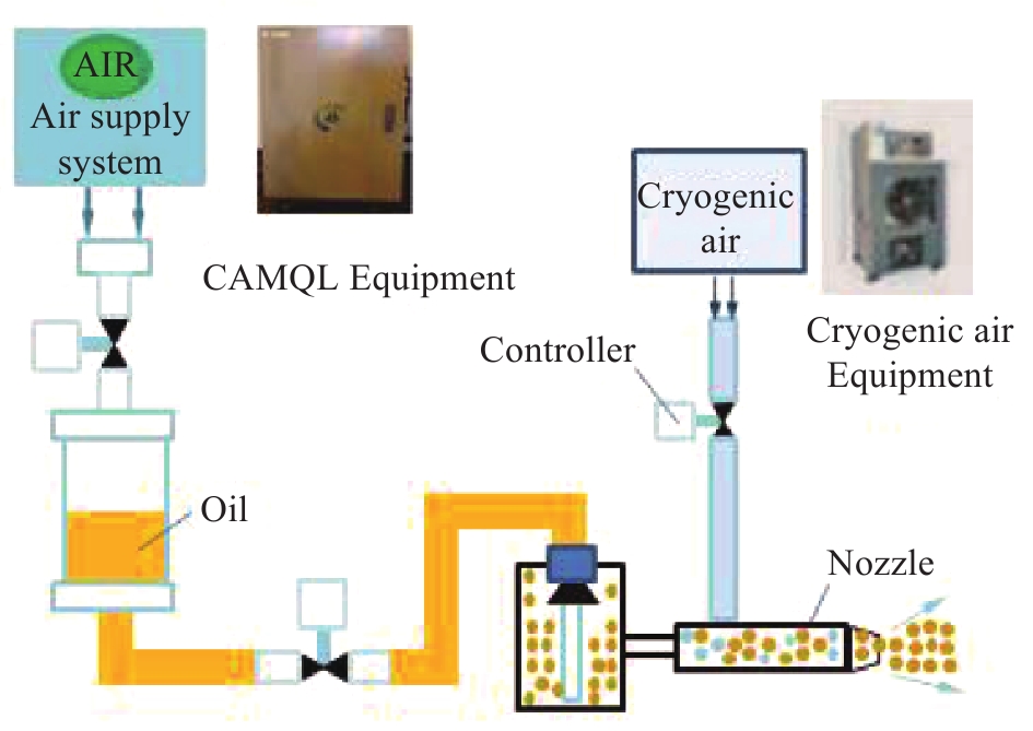
Various amounts of water (1.5, 3.0 and 4.5 L/h) and lubricants (1000-20 and 2000-30 synthetic ester, 2000-10 fatty alcohol) were utilized under the OoW cooling condition. The lubricants characteristics are presented in Table 2. For comparison, the cutting performance of the coated tools through dry cutting, flood cutting and CAMQL cooling were also investigated. The simple schematics of the CAMQL and OoW cooling equipments are presented in Table 3. For the CAMQL cooling experiments, a low amount of oil mist was delivered with a flow rate of 30 mL/h at an air pressure supply of 0.4 MPa. Consequently, the oil mist was mixed with cryogenic air (pressure supply of 0.4 MPa) and sprayed onto the cutting zone, as presented in Table 3(c). For the OoW cooling experiments, a low amount of water and micro-lubricant were mixed and atomized in the OoW equipment, consequently sprayed towards the cutting zone through compressed air of 0.4 MPa, as presented in Table 3(d). All cooling equipments were supplied by the Armorine Energy Efficient and Eco-friendly Technology Company, China.
| Table 2 Characteristics of lubricants (oils) |
| Table 3 Cooling conditions for dry cutting, flood cutting, MQL and OoW |

In the cutting processes, the cutting temperature was measured with the thermal infrared equipment (TVS-500EX, NEC®). The portable roughness meter (TR200) was utilized for the surface roughness measurements. A Kistler 9265B three-dimensional force measurement platform was utilized for the average cutting force measurements. The cutting force consisted of three components: Fx (direction of cutting feed), Fy (direction of radial depth of cut) and Fz (direction of axial depth of cut). The average cutting force was estimated through the equation: F = (Fx2+Fy2+Fz2)1/2. A stereo microscope (OLYMPUS SZ61TR, Japan) was utilized for the flank wear measurements of the coated tools subsequently to a predetermined cutting distance. An average flank wear (VB) of 0.3mm was selected as the value of tool failure. To analyze the modes of tool wear, the surface morphologies of the coated tools were observed through scanning electron microscopy (SEM, FEI, Nano430, United States) with energy-dispersive spectroscopy (EDS).
2 Results and discussion 2.1 Cutting performance of coated tools under OoW cooling conditionIn the OoW system, an important parameter is the amount of water addition to the cooling system. In order to assess the effect of various amounts of water addition on the cutting performance, various amounts of water (1.5, 3.0 and 4.5L/h) were utilized. Fig. 2(a) presents the tool wear (VB, average width of flank wear) at three different conditions. The largest tool wear was observed under the 4.5 L/h water condition, displaying the shortest tool life of approximately 160 m. The next tool wear was at the 3.0 L/h water condition. The best wear performance occurred with 1.5 L/h of water, exhibiting the longest tool life of approximately 242 m. All tests were interrupted when the value of tool failure was reached. The lower tool wear under the 1.5 L/h water condition was mainly attributed to the high lubrication efficiency, which, in conjunction with the low friction between the coated tool and the workpiece, decreased the coated tool wear. Fig. 2(b) presents the variation of cutting force of the coated tools as a function of the cutting length. It could be observed that the cutting force of the coated tool rapidly increased along with the length under the 3.0 and 4.5 L/h water conditions. The coated tool with 1.5 L/h of water displayed the lowest rate for cutting force increase, also implying an improved lubrication. Fig. 2(c) presents the effect of various amounts of water on the cutting temperature. Clearly, the cutting temperature decreased as the amount of water increased. Under the 1.5 L/h water condition, the cutting temperature was almost 280 ℃. The lower temperature was approximately 240 ℃ at the 4.5 L/h water condition. This was attributed to a large amount of water taking away more heat. The average surface roughness of the machined workpieces was measured, as presented in Fig. 2(d). From these results, it was clear that in comparison with high amounts of water (3.0 and 4.5 L/h), a small amount of water (1.5 L/h) could provide an improved surface quality. This result could be related to a good lubrication between the coated tool and the workpiece, which decreased the coated tool wear and improved the stability of machining, resulting in a lower surface roughness. The test result demonstrated that the OoW cooling could more improve the surface roughness of the machined workpiece. Apparently, the various amount of water had a significant effect on the cutting performance of the coated tool, as well as on the surface quality of the machined workpiece.

|
Figure 2 Effect of water amount through OoW cooling on: (a) flank wear; (b) cutting force; (c) cutting temperature; (d) surface roughness |
Fig. 3 presents the wear morphologies of the coated tool under various amounts of water (1.5, 3.0 and 4.5 L/h). The coated tool wear damage, especially the material adhesion, could be observed on the rake and flank faces. As presented in Fig. 3(a), for 1.5 L/h water, the main wear characteristic was adhesion wear on the rake and flank faces. When the amount of water reached 3.0 L/h water, severe abrasion wear on the rake and flank faces also existed, except the adhesion wear, as presented in Fig. 3(b). When 4.5 L/h of water were utilized, severe adhesion wear occurred. Clearly, the adhesion wear was lower under the 1.5 L/h water condition compared to both the 3.0 and 4.5 L/h water conditions, indicating that the workpiece had better lubrication. Due to the improved lubrication under the 1.5L/h water condition, it was easy for the lower friction between the coated tool and the workpiece to cause the material adhesion decrease on the rake and the flank of the coated tools. When the amount of water increased to 4.5 L/h, the effect of lubrication between the coated tool and the workpiece interface was aggravated, which significantly increased the friction force between the coated tool and the workpiece. Therefore, under the effect of strong extrusion, the cold weld phenomenon produced by plastic deformation occurred on the rake and flank faces of the coated tools, which caused severe adhesion wear on the flank of the coated tool [21].

|
Figure 3 Tool wear morphologies under various amounts of water: (a) 1.5 L/h of water; (b) 3.0 L/h of water; (c) 4.5 L/h of water |
The chip morphologies were also studied. Fig. 4 presents the chip images obtained under the 1.5, 3.0 and 4.5 L/h water conditions. It was observed that the chips were curled. Compared to the 3.0 and 4.5 L/h water conditions (corresponding to Fig. 4(b) and (c), respectively), the chips had lower radius curvature with shorter and even sizes, under the 1.5 L/h water condition (Fig. 4(a)), indicating that the lubrication was better with 1.5 L/h of water. This occurred because the good lubrication could lead the cutting edge to retain the corresponding original shape, also improving the chip formation, which led the chips to be even and integrated. Apparently, the chip morphology with a large amount of water (4.5 L/h water) was longer with irregular sizes, indicating that it was not favorable for lubrication under a large amount of water. The corresponding SEM images of the chips obtained by the coated tools are presented in Fig. 4. It was clear that serrated chips were formed on the front sides of the chips. As presented in Fig. 4(a), (b) and (c), as the amount of water decreased, the serrated chip segmentation distance apparently increased. This was due to the good lubrication under a low amount of water. When the friction decreased between the coated tool and the workpiece, the metal flow velocity increased and the serrated chip segmentation distance increased.

|
Figure 4 Optical images and chip morphologies obtained through OoW: (a) 1.5 L/h of water; (b) 3.0 L/h of water; (c) 4.5 L/h of water |
To further study the OoW cooling effect under various amounts of water, the cutting temperature of the coated tools and surface roughness of the machined materials were measured under various cutting speeds. Fig. 5(a) presents the cutting temperature of the coated tools versus the cutting speed. As presented in Fig. 5(a), the cutting temperature firstly decreased and consequently increased as the cutting speed increased. When the cutting speed reached 250 m/min, the cutting temperature increased with higher amplitude. As illustrated in Fig. 5(a), the cutting temperature with lower amplitude of the coated tool under the 1.5 L/h water condition, compared to the 3.0 and 4.5 L/h water conditions, illustrated that the cooling effect between the coated tool and the workpiece was the best under the 1.5 L/h water condition. From Fig. 5(b), it could be observed that the surface roughness first decreased with lower amplitude and consequently increased as the cutting speed increased. Apparently, the surface roughness amplitude increase was lower at the 1.5 L/h water condition compared to the 3.0 and 4.5 L/h water conditions. From these results it could be observed that a low amount of water was more favorable to lubrication. Also, comparative experiments were performed to study the OoW cooling effect under various lubricants. As illustrated in Fig. 6, the coated tool wear tool and surface roughness obtained were the minimum under the 2000-30 lubricant condition, whereas slight differences existed among three lubricants. This indicated that the lubricants had a certain effect on the cutting performance, which was not apparent.

|
Figure 5 Comparison of cutting temperatures and surface roughness values through various amounts of water for OoW: (a) cutting temperature; (b) surface roughness |

|
Figure 6 Comparison of flank wear and surface roughness through various lubricants for OoW: (a) flank wear; (b) surface roughness |
The various amount of oil also plays an important role in the OoW system. In order to assess the effect of the various amount of oil on the cutting performance, various amounts of the 2000-30 lubricant oil (20, 30,50 mL/h) was utilized. Fig. 7(a) presents the tool wear (VB, average width of flank wear) at three different conditions. The tool life obtained were the maximum under the 50 mL/h oil condition with approximately 250 m. The shortest tool wear was observed under 10 mL/h oil condition, displaying the shortest tool life of about 220 m, whereas slight differences existed among three amount of oil. Fig. 7(b) presents the cutting force of the coated tools as a function of the cutting length. It could be seen that the cutting force of the coated tools with various amount of oil was slightly different. Fig. 7(c) presents the effect of various amount of oil on the cutting temperature. Clearly, the cutting temperature is hardly different under three various amount of oil, which is about 290℃. The average surface roughness of the machined workpieces was measured, as presented in Fig. 7(d). It was clear seen that the various amount of oil had not an apparent effect on the surface roughness of the machined workpieces. From these results, it showed that the amount of oil had not obviously effect on the cutting performance.

|
Figure 7 Effect of oil amount through OoW cooling on: (a) flank wear; (b) cutting force; (c) cutting temperature; (d) surface roughness |
In conclusion, for the Oow cooling, the chip was mainly curled, a low amount of water (1.5 L/h water) had better lubrication efficiency and the lubricant and amount of oil effect on the cutting performance was not apparent.
2.2 Wear performance comparisons of coated tools under various cooling conditionsDuring experimentation, the cutting performances of the coated tool under various cooling conditions (dry cutting, Flood cutting, CAMQL and OoW) were measured. The 1.5 L/h of water was used, according to the previous better experiment results. As presented in Fig. 8(a), the flank wear rate of the coated tool rapidly increased along with the cutting distance, demonstrating the shortest tool life of approximately 74 m under the dry cutting condition. The coated tool life of the coated tool was approximately 106 m and 164 m under the flood cutting and CAMQL conditions, respectively. Adversely, under the OoW cooling condition, the flank wear rate of the coated tool was the slowest in comparison with the other conditions, possessing the longest tool life of approximately 240 m. This was attributed to good lubrication and the rapidly transferred heat from both the coated tool and the workpiece. For the OoW cooling, on the one hand, the oil film formation on the coated tool surface reduced the coated tool wear. On the other hand, the water droplets had good cooling ability, which significantly cooled down both the coated tool and the workpiece. These factors apparently improved the coated tool life. In addition, the cooling ability was important for the tribological phenomena, such as adhesion. For the CAMQL cooling, the oil films on the coated tool surface could reduce the coated tool wear, whereas the heat diffusion was not good. This occurred because the cooling ability mainly depended on cryogenic air and the air temperature was not as low as liquid nitrogen, which limited the cooling effect. Moreover, the oil films rapidly lost the corresponding lubricating effects under higher cutting temperatures, which resulted in quite severe tool friction. These results indicated that the OoW cooling could be quite suitable for the titanium alloy machining. Fig. 8(b) presents the effects of various lubrication strategies on the cutting temperature. Under the dry cutting condition, the cutting temperature was almost 400 ℃. The CAMQL lubrication produced the cutting temperature of 330 ℃. The lowest temperature was reached at approximately 280 ℃ through OoW cooling. It was clearly observed that the OoW cooling significantly decreased the cutting temperature. The surface roughness was measured, as presented in Fig. 8(c). In the dry cutting condition, the highest surface roughness of approximately 1.6 μm was obtained. On the contrary, through the OoW the lowest surface roughness of approximately 1.0 μm was obtained. As illustrated in Fig. 8(d), a comparable tool life was obtained through OoW cooling. The OoW exceeded the coated tool life by 69.2%, 56.1% and 31.6% for the dry cutting, Flood cutting and CAMQL, respectively. From these results, the OoW cooling was the best cooling strategy when the lubrication method was properly selected.

|
Figure 8 Comparisons of cutting performances of Ti-6Al-4V alloy under dry cutting, Flood cutting, CAMQL and OoW conditions: (a) flank wear; (b) cutting temperature; (c) surface roughness; (d) tool life |
Fig. 9 presents the rake and flank wear micrographs of the coated tool under the dry cutting, flood cutting, CAMQL and OoW conditions. A severe sign of material adhesion was the main wear formations on the rake and flank faces of the coated tools. Clearly, the material adhesion through the Oow was the lowest compared to the other conditions, as presented in Fig. 9(d). The dry cutting tool displayed a high-sized crater at the rake face (Fig. 9(a)), due to the high temperature in the machining zone, which aggravated the coated tool material diffusion towards the chips [20]. Adversely, this phenomenon was absent in the other conditions, indicating that the cooling could notably decrease the crater wear. Besides the severe adhesion wear, bare regions markedly existed on the flank face of the coated tools in the dry cutting, flood cutting and CAMQL tests, as presented in Fig. 9(a), (b) and (c). This was attributed to an adhesion-peel-adhesion and friction process, causing the loss of the coating materials from the coated tool substrates. The existence of the bare region A was due to the lack of lubrication on the flank faces of the coated tools. For the OoW, a slightly bare region existed on the flank face, as presented in Fig. 9(d). Clearly, the OoW cooling could significantly decrease the coated tool wear compared to the other cooling methods.

|
Figure 9 Tool wear morphologies under various lubrication conditions: (a) Dry cutting; (b) flood cutting; (c) CAMQL; (d) OoW |
To further study the cooling strategy effect on tool wear, the cross-sectional damages of the coated tools were observed with SEM with a cutting distance of 70 m. Fig. 10(a) presents a diagram of a sample cross-section observation. The sample was prepared through cutting at a distance of 1mm from the coated tool nose, whereas the cross-sectional observation area was at a distance of approximately 500μm from the flank face. It was considered that the main tool wear occurred in this area. Apparently, the coating on the rake face surface was completely damaged and a considerable amount of adhered material also existed on the surface, indicating a fast wear rate of the coated tool under the dry cutting condition, as presented Fig. 10(b). For the flood cutting and CAMQL cooling, portions of worn coatings and severely adhered materials existed on the surfaces of the rank faces, as illustrated in Fig. 10(c) and (d). Compared to dry cutting, flood cutting and CAMQL cooling, the deposited coating was almost retained except certain amounts of adhered materials on the coated tool surface. Also, the coating wear could be hardly observed on the cross-sectional area from OoW cooling, as presented in Fig. 10(e). These results further proved that the OoW cooling presented better lubrication compared to the other cooling methods during the Ti-6Al-4V alloy machining.

|
Figure 10 Cross-sectional SEM images of coated tool: (b) dry cutting; (c) Flood cutting; (d) CAMQL; (e) OoW |
The chip morphology analysis was one important way to understand the cooling effect on the chip formation. Fig. 11 presents the chip images of the coated tool, as obtained under the dry cutting, flood cutting, CAMQL and OoW conditions. Under the dry cutting and flood cutting conditions, the ribbon-shaped chip was the main chip formation, as presented in Fig. 11(a) and (b). Under the CAMQL cooling condition (Fig. 11(c)), the chip morphology was mainly curled with portions of ribbon chips. For the OoW cooling (Fig. 11(d)), the chip formation consisted of the curled chips. The chips were shorter, of more similar shapes and sizes compared to the other cooling methods under the same cutting conditions. The severe tool wear caused the cutting edge to lose the corresponding original shape and the chips were deteriorated in amount and became longer [22]. These results indicated that the OoW cooling could significantly decrease the coated tool wear and improve the chip formation. It was apparent, that serrated chip formations were observed on the front of the chips. The serrated chip segmentation distance apparently varied with various cooling methods, as presented in Fig. 11(a), (b), (c) and (d). Clearly, this distance was the longest through OoW cooling, which was attributed to good lubrication. Under the OoW cooling condition, the friction was the lowest due to good lubrication. When the friction decreased between the coated tool and the workpiece, the metal flow velocity increased, whereas the serrated chip segmentation distance increased [24].

|
Figure 11 Optical images and SEM micrographs of chips: (a) dry cutting; (b) Flood cutting; (c) CAMQL; (d) OoW |
The chip differences in shapes and sizes occurred due to the thermal effect during cutting. The temperature was different at the chip bottom and surface sides during the Ti-6Al-4V alloy machining. It could be expressed by the thermal bi-metallic spring [23], as presented in Fig. 12(a). If the temperatures between the bottom and surface sides were similar, a chip of larger radius would form (Fig. 12(b)). In contrast, if the bottom side temperature was higher compared to the surface side, the thermal effect would lead the chip to curl into a chip of smaller radius (Fig. 12(c)). Finally, curled and short chips were formed. From the SEM micrographs of the chips, the curled chips were formed through OoW cooling, due to good cooling efficiency. The OoW cooling significantly improved the temperature gradient between the bottom and surface sides, which caused the curled chips formation.

|
Figure 12 Formation of chips under various thermal effects |
Fig. 13 presents the working processes of the OoW and CAMQL lubrication methods. In the OoW cooling, compressed air and water were utilized as the heat transfer media, as well as the oils for lubrication (Fig. 13(a)). In the CAMQL cooling, the cryogenic air and oils played roles as the heat transfer media and lubricants (Fig. 13(b)), respectively. For the OoW cooling, the water droplets played the role of oil carriers. Consequently, the oils were easily spread over the surfaces of both the coated tool and the workpiece, due to the water droplets, inertia, bonding to the surfaces of both the coated tool and the workpiece, consequently penetrating the cutting zone. Moreover, the water droplets had good cooling ability, being easily evaporated from the surfaces of both the coated tool and the workpiece. Therefore, the heat on the surfaces of both the coated tool and the workpiece diffused into the atmosphere as the water was evaporated (Fig. 13(a)), which significantly cooled the surfaces of both the coated tool and the workpiece. Finally, the oils film formed (Fig. 13(b)), which contributed to good lubrication. Consequently, the coated tool life was significantly prolonged under the cooling and lubrication conditions. For the CAMQL cooling, a low of amount of oils under the compressed air flow penetrated the cutting zone. The oils film formed on the surfaces of both the coated tool and the workpiece, as presented in Fig. 13(c), which decreased the friction between the coated tool and the workpiece. The cooling ability mainly depended on the cryogenic air flow and the cooling effect was significantly limited. Subsequently, the wear resistance of the coated tool through CAMQL cooling was weaker compared to OoW cooling. It is well known that the absorption of total energy by the coated tool is approximately below 10% of the total work in high-speed machining. Therefore, the OoW cooling could sufficiently cool the coated tool, significantly reducing the coated tool wear.

|
Figure 13 Comparison of OoW and CAMQL working processes: (a) OoW cooling process; (b) CAMQL cooling process |
The cooling methods of OoW, CAMQL, flood cutting and dry cutting were investigated to clarify the cutting performance during the Ti-6Al-4V alloy high-speed milling. The coated tool wear of the coated tools was examined through certain analytical techniques. The main conclusions of this study were:
1 Oils on water (OoW) cooling had improved lubrication performance compared to dry cutting, flood cutting and CAMQL cooling.
2 The wear of the coated tool under the OoW cooling condition was the slowest compared to dry cutting, flood cutting and CAMQL cooling.
3 Compared to high amount of water conditions (3.0 L/h and 4.5 L/h water), the low amount of water condition (1.5 L/h water) provided slower tool wear and improved surface roughness under the OoW cooling condition.4 The chip morphology was mainly curled chips under the OoW and CAMQL cooling conditions, whereas it was ribbon-shaped chips through dry cutting and flood cutting, due to the thermal effect differences during cutting. The Material adhesion was the main wear performance of the coated tool through OoW cooling during the Ti-6Al-4V alloy machining.
5 Further studies could be focused on the working mechanism of oils and water during the machining of difficult-to-cut materials, whereas the dimension effect of the oil particles on the cutting performance should be taken into account as a priority.
4 Acknowledgements:The work was supported in part by the projects of the National Natural Science Foundation of China (Grant No.: 51522502), China Postdoctoral Science Foundation funded project (2016M600641) and Guangdong Natural Science Funds (2014A030311002, 2016A050502056).
| [1] |
KIM J, PARK H W. Influence of a large pulsed electron beam (LPEB) on the corrosion resistance of Ti6Al7Nb alloys[J]. Corrosi Sci, 2015, 90(6): 153-160. |
| [2] |
ZHOU Y, ZHANG Q Y, LIU J Q,et al. Wear characteristics of a thermally oxidized and vacuum diffusion heat treated coating on Ti-6Al-4V alloy[J]. Wear, 2015, 9(21): 344-345. |
| [3] |
CHE-HARON C H. Tool life and surface integrity in turning titanium alloy[J]. J Mater Process Technol, 2001, 118(1-3): 231-237. DOI:10.1016/S0924-0136(01)00926-8 |
| [4] |
LIU J, HAN R. Study on lubricating characteristic and tool wear with water vapor as coolant and lubricant in green cutting[J]. Wear, 2007, 262(3-4): 442-452. DOI:10.1016/j.wear.2006.06.014 |
| [5] |
DAVOODI B, TAZEHKANDI A H. Experimental investigation and optimization of cutting parameters in dry and wet machining of aluminum alloy 5083 in order to remove cutting fluid[J]. J Clean Prod, 2014, 68(3): 234-242. |
| [6] |
DHANANCHEZIAN M, PRADEEP K M. Cryogenic turning of the Ti-6Al-4V alloy with modified cutting tool inserts[J]. Cryogenics, 2011, 51(1): 34-40. DOI:10.1016/j.cryogenics.2010.10.011 |
| [7] |
GIASIN K, AYVAR-SOBERANIS S, HODZIC A. Evaluation of cryogenic cooling and minimum quantity lubrication effects on machining GLARE laminates using design of experiments[J]. J Clean Prod, 2016, 135(1): 533-548. |
| [8] |
LIU J Y, LIU H P, HAN R D, et al. The study on lubrication action with water vapor as coolant and lubricant in cutting ANSI 304 stainless steel[J]. Int J Mach Tools Manuf, 2010, 50(3): 260-269. DOI:10.1016/j.ijmachtools.2009.12.001 |
| [9] |
OLIVEIRA D J, GUERMANDI L G. Improving minimum quantity lubrication in CBN grinding using compressed air wheel cleaning[J]. J Mater Process Technol, 2012, 212(12): 2559-2568. DOI:10.1016/j.jmatprotec.2012.05.019 |
| [10] |
HUANG X B, ZHANG X M, MOU H, et al. The influence of cryogenic cooling on milling stability. J. Mater. Process[J]. Technol, 2014, 214(12): 3169-3178. |
| [11] |
SUN S J, BRANDT M L, PALANISAMY S, et al. Effect of cryogenic compressed air on the evolution of cutting force and tool wear during machining of Ti-6Al-4V alloy. J. Mater. Process[J]. Technol, 2015, 221: 243-254. |
| [12] |
DHAR N R, PAUL S, CHATTOPADHYAY A B. Role of cryogenic cooling on cutting temperature in turning steel[J]. J Manuf Sci Eng, 2002, 124(1): 146-154. DOI:10.1115/1.1413774 |
| [13] |
GODLEVSK V A. Water steam lubrication during machining[J]. Tribol, 1998, 162: 890-901. |
| [14] |
FAN Y H, HAO Z P, LIN J Q, et al. New observations on tool wear mechanism in machining Inconel 718 under water vaport air cooling lubrication cutting conditions[J]. J Clean Prod, 2015, 90: 381-387. DOI:10.1016/j.jclepro.2014.11.049 |
| [15] |
LI K M, CHOU S Y. Experimental evaluation of minimum quantity lubrication in near micro-milling. J. Mater. Process[J]. Technol, 2010, 210(15): 2163-2170. |
| [16] |
SARIKAYA M, TAGUCHI G A. design and response surface methodology based analysis of machining parameters in CNC turning under MQL[J]. J Clean Prod, 2014, 65(4): 604-616. |
| [17] |
MEENA A, MANSORI M E. Study of dry and minimum quantity lubrication drilling of novel austempered ductile iron (ADI) for automotive applications[J]. Wear, 2011, 271(9-10): 2412-2416. DOI:10.1016/j.wear.2010.12.022 |
| [18] |
ItOIGAWA F, CHILDS T H C, NAKAMURA T, et al. Effects and mechanisms in minimal quantity lubricationmachining of an aluminum alloy[J]. Wear, 2006, 260(3): 339-344. DOI:10.1016/j.wear.2005.03.035 |
| [19] |
YUAN S M, YAN L T, LIU L Q. Effects of cooling air temperature on cryogenic machining of Ti-6Al-4V alloy[J]. J Mater Process Technol, 2011, 211(3): 356-362. DOI:10.1016/j.jmatprotec.2010.10.009 |
| [20] |
VENUGOPAL K A, PAUL S, CHATTOPADHYAY A B. Growth of tool wear in turning of Ti-6Al-4V alloy under cryogenic cooling[J]. Wear, 2015, 262(9): 1071-1078. |
| [21] |
XU Q Z, ZHAO J, AI X. Fabrication and cutting performance of Ti(C,N)-based cermet tools used for machining of high-strength steels[J]. Ceramics International, 2017, 43(8): 6286-6294. DOI:10.1016/j.ceramint.2017.02.034 |
| [22] |
ÇALIŞKAN H, KÜÇÜKKÖSE M. The effect of aCN/TiAlN coating on tool wear, cutting force, surface finish and chip morphology in face milling of Ti6Al4V superalloy[J]. Int J Refract Met Hard Mater, 2015, 50: 304-312. DOI:10.1016/j.ijrmhm.2015.02.012 |
| [23] |
JAWAHIR I S, LUTTERVELT C A V. Recent developments in chip control research and applications[J]. CIRP Ann Manuf Technol, 1993, 42(2): 659-693. DOI:10.1016/S0007-8506(07)62531-1 |
| [24] |
WANG C Y, XIE Y X, ZHENG L J, et al. Research on the Chip Formation Mechanism during the high-speed milling of hardened steel[J]. Int J Mach Tools Manuf, 2014, 79(4): 31-48. |