智能变电站是智能电网核心节点,是集电压变换、功率交换和电能汇集分配于一体的设施. 其安全与否是智能电网能否大力发展的关键所在. 智能变电站是智能化的一次设备、网络化的二次设备和电子式互感器在IEC61850通信规约的基础上分层建立的能够实现智能设备、变电站之间的信息共享和互操作的现代化变电站[1]. 因而其继电保护可靠性的研究不能完全沿用传统方法. 目前智能变电站继电保护可靠性研究大多集中在可靠性模型的建立[2-5]和信息流连通性、时延确定及组网方式研究上[6-11]. 文献[2-3]通过OPNET软件建立变电站过程层网络的模型,研究网络的可靠性. 文献[4]用可靠性框图和邻接矩阵方法建立数字变电站继电保护模型,并评价元件的重要度等可靠性指标. 文献[5]运用可靠性框图法构建220 kV智能变电站继电保护系统的可靠性评估模型分析不同采样跳闸结构下元件灵敏度及重要度,为系统的设计和维护提供指导意义. 文献[6]分析智能变电站过程层网络所涉及的的网络报文,对比分析各报文不同的组网方式并分析各种组网方式的利弊. 文献[7]将智能变电站过程层信息流分为3大类对时报文、GOOSE报文和SV报文,采用最小路集法计算信息流的连通性,最后用串并联法求整个保护系统的可靠性. 然而值得注意的是,现有的文献只是从单一角度衡量保护系统可靠性,并无综合考量各个保护子系统对整体可靠性的影响.
本文在研究智能变电站二次保护系统设备结构的基础上[5],将其分为3个子系统即保护二次设备系统、通信子系统及人员因素子系统,研究每个子系统对保护整体可靠性的影响,并建立每个子系统的模型. 工程中对一次系统进行模糊可靠性评估状态评估的研究很多,但是对二次系统如继电保护系统研究较少[12-13],且目前可靠性研究均将可靠性参数假设为固定值,不符合实际情况降低了系统可靠性评估的可信度,本文提出基于模糊理论的马尔科夫模型[14],并建立基于此的整个智能变电站二次保护系统的Markov模型[15],综合定量计算不同系统结构及所采取不同采样跳闸方式的保护系统综合可用度,并与传统方法研究得出可靠性结果进行对比.
1 影响智能变电站保护可靠性因素 1.1 二次设备子系统对变电站可靠性的影响智能变电站全数字化保护系统的结构有多种,现研究其中2种典型[5]的结构,单套保护系统及设备冗余保护系统,其结构图如图1和图2所示.

|
图 1 单套设备保护系统结构 Figure 1 Structure of single device protection system |

|
图 2 设备冗余保护系统结构 Figure 2 Structure of equipment redundancy protection system |
单套保护系统是最基础最简单的数字保护结构,其他的保护结构都是以此为基础进行拓展得到的,由ECT/EVT采集的电压电流信号经合并单元(MU)发送给交换机(SW),交换机又将得到的数据传递给保护装置(PR),经保护装置分析处理过的数据经交换机发送给智能终(IT),最后由智能终端发送控制信号给断路器而形成一个完整的保护回路.
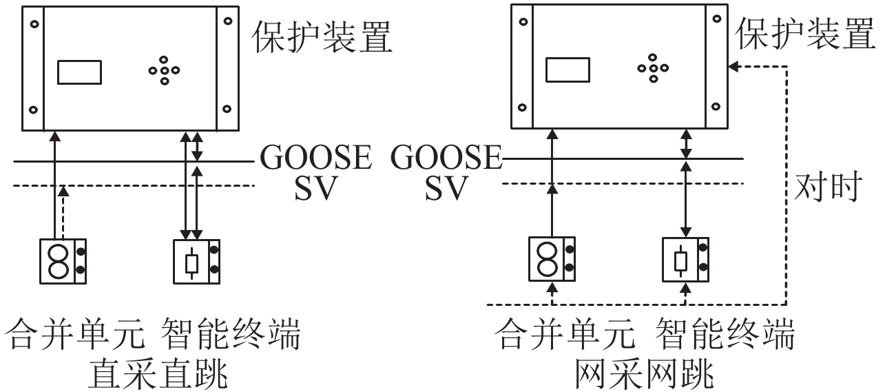
智能变电站的网络结构模式有多种[16],不同的结构下保护系统的可靠性不同,网络结构模式包括直采直跳及网采网跳,直采直跳指保护装置的电压电流采集是从本间隔的电压电流互感器直接采集,保护跳闸也是通过本间隔的GOOSE跳闸网络即直跳网络直接出口不再通过网络交换机,网采网跳即所需数据采集和输出都要经过SV,GOOSE网和网络交换机. 其结构图如图3所示.
|
图 3 不同网络结构模式 Figure 3 Different network structure mode |
采用直采直跳的网络结构模式时交换机和同步对时不影响保护可靠性,可令其失效率为零. 则单套保护结构可靠性框图如图4所示,由串并联关系求得失效率如式(1)和式(2)所示.

|
图 4 单套保护的结构框图 Figure 4 Structure block diagram of single protection |
① 网采网跳网络结构模式下的失效率
| ${\lambda _{{\rm{S1}}}}{\rm{ = }}{\lambda _{{\rm{TS}}}} + {\lambda _{{\rm{MU}}}} + {\lambda _{{\rm{SW}}}} + {\lambda _{{\rm{PR}}}} + {\lambda _{{\rm{IT}}}}. $ | (1) |
② 直采直跳网络结构模式下的失效率
| $ {\lambda _{{\rm{S1}}}}{\rm{ = }}{\lambda _{{\rm{MU}}}} + {\lambda _{{\rm{PR}}}} + {\lambda _{{\rm{IT}}}}. $ | (2) |
由图2得到结构2带节点编号的可靠性框图如图5所示,由图5找到结构2的最小路有4条,如式(3)所示.

|
图 5 设备冗余的结构框图 Figure 5 Structure block diagram of equipment redundancy |
| $ \left\{ {\begin{array}{*{20}{l}} {{P_1} = \left\{ {{\rm{TS}}1,\;{\rm{MU}}1,\;{\rm{SW}}1,\;{\rm{PR}}1,\;{\rm{IT}}1} \right\}},\\[5pt] {{P_2} = \left\{ {{\rm{TS}}2,\;{\rm{MU}}2,\;{\rm{SW}}2,\;{\rm{PR}}2,\;{\rm{IT}}2} \right\}},\\[5pt] {{P_3} = \left\{ {{\rm{TS}}1,\;{\rm{MU}}2,\;{\rm{SW}}2,\;{\rm{PR}}2,\;{\rm{IT}}2} \right\}},\\[5pt] {{P_4} = \left\{ {{\rm{TS}}2,\;{\rm{MU}}1,\;{\rm{SW}}1,\;{\rm{PR}}1,\;{\rm{IT}}1} \right\}}. \end{array}} \right. $ | (3) |
同一元件有相同的可靠性参数,令同步时钟的失效率为λTS,合并单元的失效率为λMU,交换机的失效率为λSW,保护装置的失效率为λPR,智能终端的失效率为λIT. 由式(3)及串并联关系得到该结构的总失效率为式(4)和式(5).
① 网采网跳网络结构模式下的失效率
| $\begin{array}{l}{\lambda _{{\rm{S}}2}} = 1 - (1 - {\lambda _{{\rm{TS}}}}^2)(1 - {\lambda _{{\rm{A}}1}}^2)=\\[6pt]\;\;\;\; {\lambda _{{\rm{TS}}}}^2 + {\lambda _{{\rm{A}}1}}^2 - {\lambda _{{\rm{TS}}}}^2{\lambda _{{\rm{A}}1}}^2,\end{array}$ | (4) |
式中
② 直采直跳网络结构模式下的失效率
| ${\lambda _{{\rm{S}}2}}\; = {({\lambda _{{\rm{MU}}}} + {\lambda _{{\rm{IT}}}} + {\lambda _{{\rm{PR}}}})^2}.$ | (5) |
类似于一次系统电力流可靠性取决于软硬件的有效性,二次系统通信可靠性表征为智能变电站过程层信息流的连通性及实时性. 评价通信可靠性最大难点在于信息传输过程的不透明性、信息流时延的不确定性、信息传输路线的随机性.
信息流主要以报文的形式体现,GOOSE报文主要携带的是分合闸控制、开关位置信息和防误闭锁等重要信息,在保护单元和智能终端之间进行信息交流,最后作用于控制断路器,控制断路器完成相应的操作. SV报文的功能是实现电压、电流交流量的上传,它的信息起始于互感器,经由合并单元和交换机网络后,最终传输到保护单元. IEEE1588用到的4种报文[17]:同步报文、跟随报文、延迟请求报文和延迟请求响应报文分别携带不同的时间同的时间戳及控制信息,其控制信息主要用于对各报文的识别和处理控制,而其携带的时间戳则是时钟同步的关键. SV报文携带的数据流量最大,其次为GOOSE,而对时报文携带的流量最少占用通信资源较少,故同等情况下,SV报文最易发生丢包的情况. 信息流故障与保护系统失效的对应关系如表1所示.

|
图 6 结构2的故障树 Figure 6 Fault tree of structure 2 |
| 表 1 信息流失效分析表 Table 1 Information flow failure analysis table |
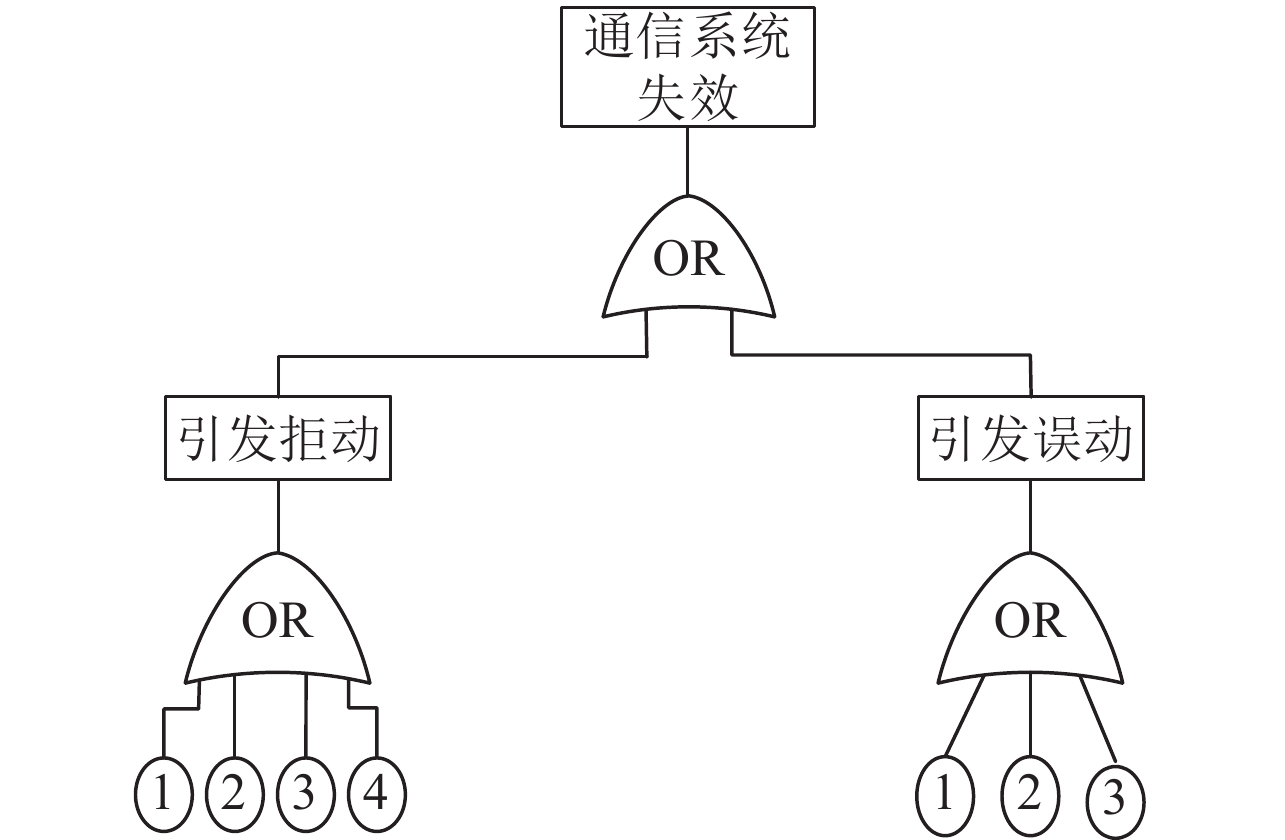
通信可靠性影响因素是由各种报文综合作用的结果,各种报文传输质量问题与系统功能失效的对应关系如表1所示. 本文选用故障树分析法,以各报文的传输质量问题为基本事件,以通信子系统失效为顶事件得到的故障树如图6和图7所示,不同的系统配置结构其故障树也不同.
|
图 7 结构1的故障树 Figure 7 Fault tree of structure 1 |
设Pi(i=1, 2, 3, 4)表示事件i发生的概率,由下行法求得结构1的失效参数为
| $\left\{ {\begin{array}{*{20}{l}}{{\lambda _i} = 2{p_1} + 2{p_2} + 2{p_3} + {p_4}},\\[6pt]{{\lambda _{i{\rm{w}}}} = {p_1} + {p_2} + {p_3}},\\[6pt]{{\lambda _{i{\rm{j}}}} = {p_1} + {p_2} + {p_3} + {p_4}};\end{array}} \right.$ | (6) |
结构2的失效参数为
| $\left\{ {\begin{array}{*{20}{l}}{{\lambda _i} = {{({p_1} + {p_2} + {p_3} + {p_4})}^4} + {{({p_1} + {p_2} + {p_3})}^4}},\\[6pt]{{\lambda _{i{\rm{j}}}} = {{({p_1} + {p_2} + {p_3} + {p_4})}^4}},\\[6pt]{{\lambda _{i{\rm{w}}}} = {{({p_1} + {p_2} + {p_3})}^4}}.\end{array}} \right.$ | (7) |
式中λij表示因信息流故障导致的拒动率,λiw表示因信息流故障导致的误动率.
1.3 人员子系统建模及对可靠性的影响随着现代工业制造水平的提高,现代电力设备的可靠性越来越高,因此人员误操作因素成为变电站事故的主要影响因素之一. 根据《电力系统继电保护及安全自动装置运行评价规程》的定义[18],不考虑制造部门、设计部门、基建部门人员误操作的影响,已经将它们归结到变电站二次物理设备的层面,属于变电站人员误操作的范畴是指调度运行部门、值班运行、维护检修部门和其他部门人员的误操作. 据统计,在220 kV及以上电压等级系统中因人员误操作导致的故障占约38%[19].
人员可靠性的分析不同于电气设备具有确定性,由于人的主观性、生理或心理因素,且与系统及外部环境存在相关性及交互性,导致很难进行量化分析. 由于变电站中人员误操作数据的缺乏,现采用通用模型,即人的认知可靠性模型(HCR)[20],HCR是采用人机工程学及认知心理学原理来评价运行值班人员未能在规定的时间内完成规定的任务的概率的一种模型. HCR模型中的失误概率服从3参数的威布尔分布. 其失效概率公式如式(8)所示.
| ${\lambda _{\rm{r}}} = {{\rm{e}}^{ - {{\left\{ {\frac{{\frac{t}{{{T_{0.5}}}} - \gamma }}{\alpha }} \right\}}^\beta }}}.$ | (8) |
式中t表示允许操作人进行响应的时间,T0.5表示操作人员的执行时间,α、β、γ表示与行为相关的尺度、形状及位置参数.
因人员因素的不确定性现将人员失效率模糊化,根据人员行为分为知识型、规则型和技能型,其参数选取如表2所示,不同的行为类型α、β、γ的取值不同得到的失效率是一个模糊区间. 假定因人员因素导致的失误中拒动和误动各占一半,
| ${\lambda _{\rm{rj}}} = {\lambda _{\rm{rw}}}{\rm{ = 0}}{\rm{.5}}{\lambda _{\rm{r}}}.$ | (9) |
| 表 2 HCR模型部分参数选取表 Table 2 Partial parameters of HCR model |
以往求解智能变电站可靠性指标都是以整个系统有效寿命期的平均值代替实际值,在一定程度上可以表征其系统的可靠性,但不足以令人信服.
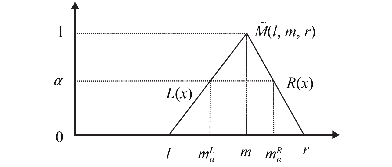
由于产品的质量、设备的运行环境、系统的维修检修水平、各种参数的统计方法以及系统的复杂程度,导致系统的可靠性参数具随机的分散性[15]. 而模糊理论正是研究这种不确定理论的有效工具. 本文采用三角正则模糊数表示系统的可靠性参数,简记为
|
图 8 三角模糊数 Figure 8 Triangular fuzzy number |
图8中
| ${m_{\widetilde M}}(x) = \left\{{\begin{array}{*{20}{c}}{\frac{\displaystyle{x - l}}{\displaystyle{m - l}},l \leqslant x \leqslant m},\\[6pt]{ \frac{\displaystyle{x - r}}{\displaystyle{m - r}},m \leqslant x \leqslant r}.\end{array}} \right.$ | (10) |
由式(10)可将模糊可靠性参数λ、μ一一对应在实数域上.
其四则运算的具体表达式为
| $\left\{ {\begin{array}{*{20}{c}}{{\text{模糊加法}}: {{(M({\rm{ + )}}N)}_a} = [m_a^L + n_a^L,m_a^R + n_a^R]},\\[6pt]{{\text{模糊减法}}: {{(M( - {\rm{)}}N)}_a} = [m_a^L - n_a^L,m_a^R - n_a^R]},\\[6pt]{{\text{模糊乘法}}: {{(M( \times {\rm{)}}N)}_a} = [m_a^L \times n_a^L,m_a^R \times n_a^R]},\\[6pt]{{\text{模糊除法}}: {{(M( \div {\rm{)}}N)}_a} = [m_a^L \div n_a^L,m_a^R \div n_a^R]}.\end{array}} \right.$ | (11) |
传统的马尔科夫状态空间法无法求解转移率为模糊指数分布的系统,因此需将传统的马尔科夫模型进行模糊化处理. 即对传统马尔科夫模型的状态方程进行模糊化处理,得到处理后的方程式为
| $\left\{ {\begin{array}{*{20}{c}}{\widetilde {{{P}}(n)} \cdot \widetilde {{A}} = 0},\\[6pt]{\sum\nolimits_{i = 1}^n {\widetilde {{{P}}(i)} = 1} }.\end{array}} \right.$ | (12) |
式中
若取α=0,0.1,……,1,则可将式(12)分割为11个方程组,如式(13)所示.
| $\left\{ {\begin{array}{*{20}{c}}{\widetilde {{{{P}}_\alpha }(n)} \cdot \widetilde {{{{A}}_\alpha }} = 0},\\[6pt]{\sum\nolimits_{i = 1}^n {\widetilde {{{{P}}_\alpha }(i)} = 1} }.\end{array}} \right.$ | (13) |
通过式(12)可得到不同置信水平下各状态的平稳概率
智能变电站继电保护系统的可修复性使其可沿用状态空间法求解其可靠性指标. 在建立其模糊可靠性框图时做以下假定:① 各个子系统失效互不影响;② 各子系统都具自诊断能力,失效后即可以一定修复率修复并不引进新的故障;③ 各子系统失效都会导致保护误动或拒动,其概率视具体情况而定. ④ 设备子系统已包含硬件和软件.
在以上假设下的智能变电站二次继电保护系统的状态空间如图9所示.

|
图 9 网采网跳模式下继电保护状态空间图 Figure 9 State space diagram of relay protection under net-sampling-net-tripping mode |
由状态空间图得到的模糊状态转移矩阵
| $\widetilde {{A}} = \left[ {\begin{array}{*{20}{c}}{ - \theta } & {\widetilde {{\lambda _1}}} & {\widetilde {{\lambda _2}}} & {\widetilde {{\lambda _3}}} & {\widetilde {{\lambda _4}}} & {\widetilde {{\lambda _5}}} & {\widetilde {{\lambda _6}}}\\[5pt]{\widetilde {{\mu _1}}} & { - \widetilde {{\mu _1}}} & 0 & 0 & 0 & 0 & 0\\[5pt]{\widetilde {{\mu _2}}} & 0 & { - \widetilde {{\mu _2}}} & 0 & 0 & 0 & 0\\[5pt]{\widetilde {{\mu _3}}} & 0 & 0 & { - \widetilde {{\mu _3}}} & 0 & 0 & 0\\[5pt]{\widetilde {{\mu _4}}} & 0 & 0 & 0 & { - \widetilde {{\mu _4}}} & 0 & 0\\[5pt]{\widetilde {{\mu _5}}} & 0 & 0 & 0 & 0 & { - \widetilde {{\mu _5}}} & 0\\[5pt]{\widetilde {{\mu _6}}} & 0 & 0 & 0 & 0 & 0 & { - \widetilde {{\mu _6}}}\end{array}} \right].$ | (14) |
式中
| $\widetilde {{{P}}\left( n \right)} = [\widetilde {{{P}}\left( 0 \right)},\widetilde {{{P}}\left( 1 \right)},\widetilde {{{P}}\left( 2 \right)},\widetilde {{{P}}\left( 3 \right)},\widetilde {{{P}}\left( 4 \right)},\widetilde {{{P}}\left( 5 \right)},\widetilde {{{P}}\left( 6 \right)}].$ | (15) |
联立式(13)、(14)和(15)可以解得
| $\begin{split}\widetilde {{{P}}(0)} = \beta /(\beta + \widetilde {{\lambda _1}}\widetilde {{\mu _2}}\widetilde {{\mu _3}}\widetilde {{\mu _4}}\widetilde {{\mu _5}}\widetilde {{\mu _6}} + \widetilde {{\mu _1}}\widetilde {{\lambda _2}}\widetilde {{\mu _3}}\widetilde {{\mu _4}}\widetilde {{\mu _5}}\widetilde {{\mu _6}}+\\[3pt]\;\;\;\;\;\;\;\;\;\;\;\;\;\;\;\; \widetilde {{\mu _1}}\widetilde {{\mu _2}}\widetilde {{\lambda _3}}\widetilde {{\mu _4}}\widetilde {{\mu _5}}\widetilde {{\mu _6}} + \widetilde {{\mu _1}}\widetilde {{\mu _2}}\widetilde {{\mu _3}}\widetilde {{\lambda _4}}\widetilde {{\mu _5}}\widetilde {{\mu _6}}+\\[3pt]\;\;\;\;\;\;\;\;\;\;\;\;\;\;\;\; \widetilde {{\mu _1}}\widetilde {{\mu _2}}\widetilde {{\mu _3}}\widetilde {{\mu _4}}\widetilde {{\lambda _5}}\widetilde {{\mu _6}} + \widetilde {{\mu _1}}\widetilde {{\mu _2}}\widetilde {{\mu _3}}\widetilde {{\mu _4}}\widetilde {{\mu _5}}\widetilde {{\lambda _6}}).\end{split}$ | (16) |
| $\widetilde {{{P}}(i)} = \widetilde {{{P}}(0)} \cdot \widetilde {{\lambda _i}}/\widetilde {{\mu _i}}\;,\;\;i = 1,2, \cdot \cdot \cdot ,6. \qquad \qquad \quad \;\;\;$ | (17) |
直采直跳模式报文不走网络,因此通信子系统对保护系统可靠性的影响可以忽略不计. 在设备子系统中网络交换机及对时系统对保护的可靠性没有影响,因此设备子系统的失效率需重新计算. 经修正后得到直采直跳模式下继电保护状态空间如图10所示.

|
图 10 直采直跳模式下继电保护状态空间图 Figure 10 State space diagram of relay protection under direct- sampling-direct-tripping mode |
由状态空间图得到系统状态转移矩阵
| $\widetilde {{B}} = \left[ {\begin{array}{*{20}{c}}{ - {\theta _1}} & {\widetilde {{\lambda _1}}} & {\widetilde {{\lambda _2}}} & {\widetilde {{\lambda _3}}} & {\widetilde {{\lambda _4}}}\\[5pt]{\widetilde {{\mu _1}}} & { - \widetilde {{\mu _1}}} & 0 & 0 & 0\\[5pt]{\widetilde {{\mu _2}}} & 0 & { - \widetilde {{\mu _2}}} & 0 & 0\\[5pt]{\widetilde {{\mu _3}}} & 0 & 0 & { - \widetilde {{\mu _3}}} & 0\\[5pt]{\widetilde {{\mu _4}}} & 0 & 0 & 0 & { - \widetilde {{\mu _4}}}\end{array}} \right],$ | (18) |
式中
| $\widetilde {{{P}}(n)} = [\widetilde {{{P}}(0)},\widetilde {{{P}}(1)},\widetilde {{{P}}(2)},\widetilde {{{P}}(3)},\widetilde {{{P}}(4)}].$ | (19) |
联立式(13)、(18)和(19)可以解得
| $\begin{split}\widetilde {{{P}}(0)} = {\beta _1}/({\beta _1} + \widetilde {{\lambda _1}}\widetilde {{\mu _2}}\widetilde {{\mu _3}}\widetilde {{\mu _4}} + \widetilde {{\mu _1}}\widetilde {{\lambda _2}}\widetilde {{\mu _3}}\widetilde {{\mu _4}}+\\\;\;\;\;\;\;\;\;\;\;\;\;\;\;\;\; \widetilde {{\mu _1}}\widetilde {{\mu _2}}\widetilde {{\lambda _3}}\widetilde {{\mu _4}} + \widetilde {{\mu _1}}\widetilde {{\mu _2}}\widetilde {{\mu _3}}\widetilde {{\lambda _4}}),\end{split}$ | (20) |
| $\widetilde {{{P}}(i)} = \widetilde {{{P}}(0)} \cdot \widetilde {{\lambda _i}}/\widetilde {{\mu _i}}\;,\;\;i = 1,2,3,4.$ | (21) |
式中
本文基于模糊可靠性参数,运用状态空间法计算不同设备配置结果及其网络通信的综合可靠性,并分析不同采样跳闸方式下整个保护系统的综合可用度,最后用MATLAB对结果进行仿真.
本文部分数据来源于文献[4~6, 20]及部分现场数据,汇总得到智能变电站保护系统模糊可靠性参数如表3,4和5所示.
| 表 3 设备系统可靠性参数 Table 3 Reliability parameters of equipment system |
| 表 4 通信系统可靠性参数 Table 4 Reliability parameters of communication system |
| 表 5 人员因素系统可靠性参数 Table 5 Reliability parameters of personnel factor system |
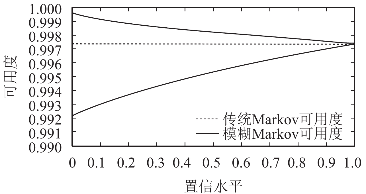
将表3、4和5数据代入式(1)、(7)、(11)、(16)和(21)进行模糊四则运算,并对单套保护系统进行仿真计算得到传统模型和模糊模型的可靠性参数如图11、12和13所示.
|
图 11 不同模型可用度的比较 Figure 11 The comparison of availability of different models |
由图11可以看出,相比于传统Markov模型,模糊Markov模型能全面地表征保护系统在不同工况、不同环境下的综合可用度,虚线以上表示保护系统工作在工况良好、环境优越的情况,虚线以下表示保护系统工作在工况较差且环境恶劣的情况下,由此可看出模糊Markov状态空间法具有更强的适应性. 技术人员可根据不同的条件选择合适的置信水平从而得到精确的综合可用度.
图12为单套保护在不同网络结构模式下的可用度,可以看出直采直跳模式下的可用度大于网采网跳模式,这一结果与《智能变电站继电保护技术规范》[21]中的要求即单间隔保护应采用直采直跳相符.

|
图 12 不同网络结构模式下可用度对比 Figure 12 The comparison of availability under different network structure models |
图13为单套保护和设备冗余两种结构在网采网跳网络结构模式下的可用度对比,由图可知设备冗余这一保护结构的可靠性大于单套保护,且设备冗余可靠性不管在优越环境还是恶劣环境下的可用度接近于1. 这与《智能变电站继电保护技术规范》中220 kV及以上电压等级的继电保护及与之相关的设备和网络等应按照双重化配置这一原则相符.
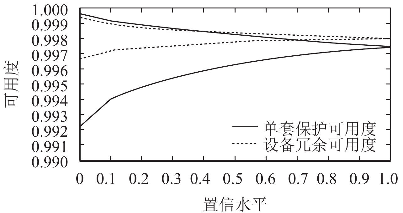
|
图 13 不同结构下可用度对比 Figure 13 The comparison of availability under different structures |
(1) 本文建立了智能变电站保护系统的二次设备、通信及人员子系统的模型,并建立其模糊Markov状态空间模型,最后求解其综合可用度. 通过对比文献[5, 22]的数据可得智能变电站继电保护系统在考虑通信方面影响因素后其可靠性数据低于传统保护.
(2) 经模糊Markov状态空间法得到的综合可用度能准确表征保护系统在各种状态下的可靠性指标,且经模糊化处理的通信子系统的可靠性参数可以有效地避免信息流的不确定性及人为的主观性.
(3) 最后由结果可知本文所建立的智能变电站保护子系统模型及对其可靠性的评估具有一定的合理性及实用性,对智能变电站保护系统的架构具有一定的指导作用.
| [1] | 高翔. 智能变电站变技术[M]. 北京: 中国电力出版社, 2012. |
| [2] |
黄明辉, 邵向潮, 张弛, 等. 基于OPNET的智能变电站继电保护建模与仿真[J].
电力自动化设备, 2013, 5(33): 144-149.
HUANG M H, SHAO X C, ZHANG C, et al. Modeling and simulation of relay protection for intelligent substation based on OPNET[J]. Electric Power Automation Equipment, 2013, 5(33): 144-149. |
| [3] |
方晓洁, 季夏轶, 卢志刚. 基于OPNET的数字化变电站继电保护通信网络仿真研究[J].
电力系统保护与控制, 2010, 23(38): 137-140.
FANG X J, JI X Y, LU Z G. Study on relaying protection communication network in digital substation using OPNET simulation[J]. Power System Protection and Control, 2010, 23(38): 137-140. |
| [4] |
张沛超, 高翔. 全数字化保护系统的可靠性及元件重要度分析[J].
中国电机工程学报, 2008, 1(28): 77-82.
ZHANG P C, GAO X. Analysis of reliability and component importance for all-digital protective systems[J]. Proceedings of the Chinese Society for Electrical Engineering, 2008, 1(28): 77-82. |
| [5] |
张跃丽, 陈幸琼, 王承民, 等. 智能变电站二次系统可靠性评估[J].
电网与清洁能源, 2012, 11(28): 7-12.
ZHANG Y L, CHEN X Q, WANG C M, et al. Reliability assessment of intelligent substation secondary system[J]. Advances of Power System & Hydroelectric Engineering, 2012, 11(28): 7-12. |
| [6] |
樊陈, 倪益民, 窦仁辉, 等. 智能变电站过程层组网方案分析[J].
电力系统自动化, 2011, 18(35): 67-71.
FAN C, NI Y M, DOU R H, et al. Analysis of network scheme for process layer in smart substation[J]. Automation of Electric Power Systems, 2011, 18(35): 67-71. |
| [7] |
王超, 王慧芳, 张弛, 等. 数字化变电站继电保护系统的可靠性建模研究[J].
电力系统保护与控制, 2013, 41(3): 8-13.
WANG C, WANG H F, ZHANG C, et al. Study of reliability modeling for relay protection system in digital substations[J]. Power System Protection and Control, 2013, 41(3): 8-13. DOI: 10.7667/j.issn.1674-3415.2013.03.002. |
| [8] |
于军, 熊小伏, 张媛. 数字化变电站保护系统可靠性新措施及仿真[J].
电网技术, 2009, 33(4): 28-33.
YU J, XIONG X F, ZHANG Y. Research and simulation on new reliability measures for digital substation protection system[J]. Power System Technology, 2009, 33(4): 28-33. |
| [9] |
何瑞文, 谢琼香, 蔡泽祥. 数字化电气信息采集对继电保护可靠性的影响[J].
广东工业大学学报, 2013, 2(30): 68-72.
HE R W, XIE Q X, CAI Z Q. Influence of digital acquisition of the electrical information on the reliability of relay protection[J]. Journal of Guangdong University of Technology, 2013, 2(30): 68-72. |
| [10] |
陈少华, 陈璟华, 杨宜民. 基于多Agent技术的自适应继电保护系统研究[J].
广东工业大学学报, 2005, 1(22): 78-83.
CHEN S H, CHEN J H, YANG Y M. Study on adaptive protection system based on multi-agent[J]. Journal of Guangdong University of Technology, 2005, 1(22): 78-83. |
| [11] |
徐春霞, 张艳霞, 葛跃田. 智能变电站过程层网络数据流的分析与研究[J].
中国电力, 2013, 46(8): 153-159.
XU C X, ZHANG Y X, GE Y T. Analysis and study on intelligent substation process level network data stream[J]. Electric Power, 2013, 46(8): 153-159. |
| [12] |
吴姜, 蔡泽祥, 胡春潮, 等. 基于模糊正态分布隶属函数的继电保护装置状态评价[J].
电力系统保护与控制, 2012, 40(5): 48-52.
WU J, CAI Z X, HU C C, et al. Status evaluation of protective relays based on the membership function in fuzzy normal distribution[J]. Power System Protection and Control, 2012, 40(5): 48-52. DOI: 10.7667/j.issn.1674-3415.2012.05.009. |
| [13] |
刘永欣, 师峰, 姜帅, 等. 智能变电站继电保护状态监测的一种模糊评估算法[J].
电力系统保护与控制, 2014, 42(3): 37-41.
LIU Y X, SHI F, JIANG S, et al. A fuzzy evaluation algorithm for condition monitoring of smart substation relay protection[J]. Power System Protection and Control, 2014, 42(3): 37-41. DOI: 10.7667/j.issn.1674-3415.2014.03.006. |
| [14] | 谢季坚, 刘承平. 模糊数学方法及其应用[M]. 第四版. 武汉: 华中科技大学出版社, 2013. |
| [15] | 程林, 何剑. 电力系统可靠性原理和应用[M]. 第二版. 北京: 清华大学出版社, 2015. |
| [16] |
王同文, 谢民, 孙月琴, 等. 智能变电站继电保护系统可靠性分析[J].
电力系统保护与控制, 2015, 43(6): 58-66.
WANG T W, XIE M, SUN Y Q, et al. Analysis of reliability for relay protection systems in smart substation[J]. Power System Protection and Control, 2015, 43(6): 58-66. DOI: 10.7667/j.issn.1674-3415.2015.06.010. |
| [17] | 高会生. 电力通信网可靠性研究[D]. 保定: 华北电力大学电气与电子工程学院, 2009. |
| [18] | 国家能源局. 电力系统继电保护及安全自动装置运行评价规程: DL/T 623-2010[S]. 北京: 中国电力出版社, 2011. |
| [19] |
陈少华, 马碧燕, 雷宇, 等. 综合定量计算继电保护系统可靠性[J].
电力系统自动化, 2007, 31(15): 111-115.
CHEN S H, MA B Y, LEI Y, et al. Integrative and quantitative calculation of reliability for relay protection system[J]. Automation of Electric Power Systems, 2007, 31(15): 111-115. DOI: 10.3321/j.issn:1000-1026.2007.15.024. |
| [20] |
王洪德, 高玮. 基于人的认知可靠性(HCR)模型的人因操作失误研究[J].
中国安全科学学报, 2006, 16(7): 51-56.
WANG H D, GAO W. Study on erroneous operation due to human factor based on human cognitive reliability (HCR) model[J]. China Safety Science Journal, 2006, 16(7): 51-56. |
| [21] | 国家电网公司. 智能变电站继电保护技术规范: QGDW 441-2010[S]. 北京: 中国电力出版社, 2011. |
| [22] |
张烈, 吕鹏飞, 申华, 等. 2013年国家电网公司220 kV及以上电压等级交流系统继电保护设备及其运行情况分析[J].
电网技术, 2015, 39(4): 1153-1159.
ZHANG L, LYU P F, SHEN H, et al. Analysis on protective relaying and its operation conditions of SGCC in 220 kV and above voltage AC systems in 2013[J]. Power System Technology, 2015, 39(4): 1153-1159. |
 2017, Vol. 34
