在电动汽车快速发展的同时,对电动汽车电池快速充电的要求越来越高。现在主要的快速充电方式有脉冲充电法[1-2]、定化学反应状态法、变电流间歇充电法以及变电压间歇充电法等[3-4]。脉冲充电法,由于电池充电末期所需电流较小,开关电源的导通占空比很小,控制难度加大[5]。定化学反应状态法,虽然充电效率较高,但是制造成本高且充电不完全。变电流/电压间歇充电法,如果电流电压控制不当容易出现电池失水、微短路、硫酸极化等现象[6-7]。此外,上述几种快速充电方式多采用温度控制法、时间控制法、最高电压控制法等快速充电控制技术[8],这些控制技术受电池温度、循环次数等因素影响较大。
因此,考虑电池容量衰减和电池内阻损失等对SOC(state of charge)估算的影响,提出改进型能量守恒SOC估算方法,并根据电池的充电特性,提出三段式(小电流充电、脉冲充电、恒压充电)快速智能充电方式,以缩短电池充电时间,且降低电池温度、循环次数等因素对充电的影响,增强快速充电的安全性与可靠性。
1 改进型能量守恒SOC估算法 1.1 传统能量守恒SOC估算法传统能量守恒法的电池SOC估算策略[9]表达式如下:
| $ {\rm{SOC = }}\frac{{{W_{{\rm{battery}}}} + \int_0^t {E\left( {{\rm{soc}}} \right) \cdot I{\rm{d}}t} }}{{{W_{{\rm{battery}}}}}} $ | (1) |
式中:E(soc)为蓄电池电动势,Wbattery为电池总能量。
上述估算法能够较好地实时估算在动态状况下的荷电状态,但是没有考虑电池容量衰减、电池内阻损失对估算SOC的影响。针对传统能量守恒法的缺陷,考虑电池容量衰减、电池内阻损失对SOC估算的影响,提出改进型能量守恒SOC估算方法。
1.2 改进型能量守恒SOC估算方程影响电池容量衰减[10]的因素有电池充放电循环次数[11]、充放电倍率、温度[12]、充放电深度。电池容量衰减可表示为[13]:
| $ {C_{{\rm{fade}}}} = {C_{{\rm{rated}}}}\left( {1-{L_{{\rm{rate}}}}} \right) $ | (2) |
式中:Cfade为电池衰减后剩余容量,Crated为电池额定容量,Lrate为电池容量衰减率。
由于电池容量衰减率符合Arrhenius模型[14],Lrate可表示为:
| $ {L_{{\rm{rate}}}} = {A_0} \cdot \exp \left( {\frac{{-{E_a}}}{{{\rm{R}} \cdot T}}} \right) \cdot {\left( {n \cdot {C_{{\rm{rated}}}}} \right)^a} $ | (3) |
则Cfade可表示为:
| $ {C_{{\rm{fade}}}} = {C_{{\rm{rated}}}} \cdot \left[{1-{A_0} \cdot \exp \left( {\frac{{-{E_a}}}{{{\rm{R}} \cdot T}}} \right) \cdot {{\left( {n \cdot {C_{{\rm{rated}}}}} \right)}^a}} \right] $ | (4) |
| $ n = {n_{{\rm{Cycle}}}} + {n_{{\rm{Cycl}}{{\rm{e}}_0}}} $ | (5) |
式中:n为电池总循环次数,nCycle为电池实验循环次数,nCycle0为电池实验开始之前已循环次数,这里取0。
为便于计算,可将公式(3) 指数形式变化为线性形式:
| $ \ln \left( {{L_{{\rm{rate}}}}} \right) + \frac{{{E_a}}}{{{\rm{R}} \cdot T}} = \ln \left( {{A_0}} \right) + a \cdot \ln \left( {n \cdot {C_{{\rm{rated}}}}} \right) $ | (6) |
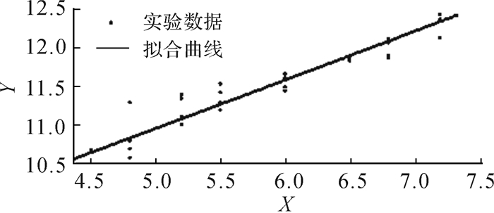
根据电池实际工作状况和实验设备条件,设置实验时温度T=50 ℃,电池实验循环次数为100次。根据电池充放电参数识别实验数据,可得到如图 1所示的参数线性关系,其中坐标Y=ln(Lrate)+Ea/(RT),X=ln(n·Crated)。
|
| 图 1 电池充放电参数辨识实验结果 Fig.1 Experimental result of parameter identification for battery charging and discharging |
得到的拟合公式表达式为:
| $ Y = 0.5712 \cdot X + 8.161 $ | (7) |
其中:参数a等于拟合公式斜率,为0.571 2;ln(A0)等于拟合公式截距,为8.161,A0=3 502;Lrate由实验得到,循环100次时ln(Lrate)=2.803;R为气体常数,R=8.31;Ea=25 118。
将求得参数代入公式(4),可得:
| $ {C_{{\rm{fade}}}} = 11 \times \left[{1-3502 \times \exp \left( {\frac{{-25118}}{{8.31 \times T}}} \right) \times {{\left( {11 \times {n_{{\rm{Cycle}}}}} \right)}^{0.5712}}} \right] $ | (8) |
加入电池容量衰减因素后电池总能量可表示为:
| $ {W_{{\rm{battery1}}}} = {C_{{\rm{fade}}}} \cdot {E_0} $ | (9) |
电池内阻损失Rloss为:
| $ {R_{{\rm{loss}}}} = \int_0^t {R \cdot {I^2}{\rm{d}}t} $ | (10) |
增加电池容量衰减和内阻损失影响因素后的SOC为:
| $ {\rm{SOC = SO}}{{\rm{C}}_0} + \frac{{\int_0^t {E\left( {{\rm{soc}}} \right) \cdot I{\rm{d}}t + \int_0^t {R \cdot {I^2}{\rm{d}}t} } }}{{{W_{{\rm{battery1}}}}}} $ | (11) |
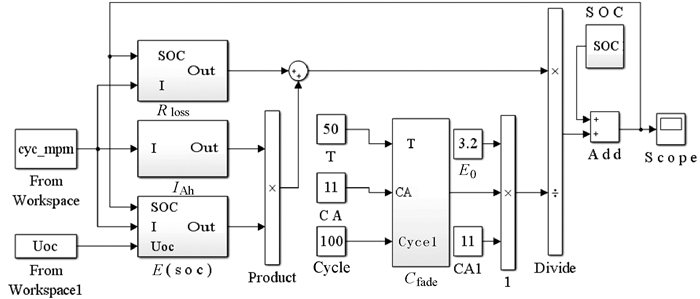
根据上述SOC估算方程建立电池SOC估算仿真模型,如图 2所示。
|
| 图 2 改进型SOC估算仿真模型 Fig.2 Improved SOC estimation simulation model |
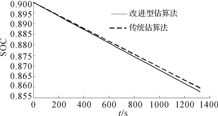
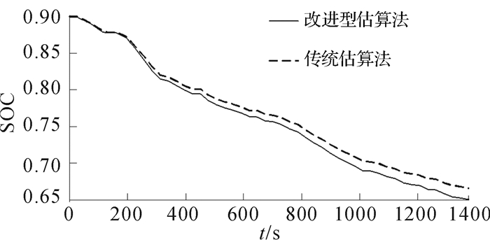
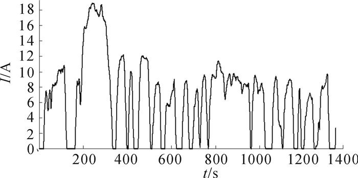
其中子系统Rloss为电池内阻损失,IAh为电流积分。根据公式(11) 可知,随着电池充放电循环次数的增加,电池容量衰减增加,电池实际容量小于额定容量,即公式(11) 计算出的SOC要小于公式(1) 中SOC。而且随着容量衰减的逐渐增加和内阻能量损失的累积,两者差值越来越大。为验证模型的准确性,设置初始SOC为0.9,传统和改进型能量守恒法在0.1 C恒定电流(1.1 A)放电工况下的SOC变化如图 3所示。本文选取UDDS工况对电池模型进行仿真,考虑电池容量,采用1/3倍UDDS工况电流作为实际仿真工况的放电电流,SOC的变化和放电电流的变化如图 4和5所示。
|
| 图 3 0.1 C恒定电流放电工况下2种估算算法获取的SOC曲线 Fig.3 SOC curves obtained by the two estimation algorithms under 0.1 C constant current discharging condition |
|
| 图 4 1/3倍UDDS工况电流放电时2种估算算法获取的SOC曲线 Fig.4 SOC curves obtained by the two estimation algorithms during discharging with 1/3 times UDDS condition current |
|
| 图 5 1/3倍UDDS工况电流放电时的电流变化 Fig.5 The change of current during discharging with 1/3 times UDDS condition current |
显然,改进型能量守恒SOC估算法得到的SOC值要小于传统能量守恒法,更加接近于真实的SOC值,也符合上述理论分析。
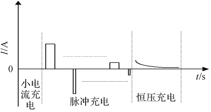
2 三段式智能充电方式根据电池过放后适合小电流预充电的特性,防止大电流持续充电造成的过充,提出三段式智能充电方式,即第1阶段为小电流充电,第2阶段为脉冲充电,第3阶段为恒压充电。由于传统快充控制方法的缺陷,本文采用改进型能量守恒SOC估算法估算所得的SOC值作为三段式智能充电各阶段的判断依据,这种充电方式更加有利于电池快速充电。
1) 小电流充电。
当SOC值低于20%,若采用大电流充电,电池内部化学反应剧烈,这会对电池造成损失,所以采用小电流(0.1C)充电。
2) 脉冲充电。
当SOC值在20%~80%区间时,采用脉冲充电。
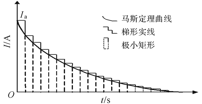
考虑电动汽车蓄电池充电的安全性与快速性,脉冲充电电流可根据马斯定律[15]进行设定,充电电流可表示为:
| $ {I_{\rm{c}}} = {I_{\rm{a}}} \cdot {{\rm{e}}^{-c \cdot t}} $ | (12) |
式中:Ia为t=0时刻的最大电流值,c是充电电流接受比。
图 6中曲线为马斯定理曲线,由于该曲线是指数形式,如按照该曲线充电会增加电路设计难度,控制策略相对复杂。为降低硬件设计难度,简化控制策略,本设计用极小的矩形组代替马斯定理曲线,图 6中阶梯实线为阶梯形充电电流。
|
| 图 6 基于马斯定理曲线的阶梯形充电电流 Fig.6 Step type charging current based on Maas theorem curve |
图 6中的阶梯形充电电流的电容量为各矩形面积之和:
| $ {Q_1} = \sum\limits_0^t {\Delta t \cdot {I_i}} $ | (13) |
式中:Δt为矩形宽度,Ii为矩形高度。
采用马斯定理曲线充电,相同时间内的电容量为:
| $ Q = \int_0^{i \cdot \Delta t} {{I_{\rm{a}}}} \cdot {{\rm{e}}^{-c \cdot t}}{\rm{d}}t $ | (14) |
| $ \Delta Q = {Q_1}-Q $ | (15) |
ΔQ为Q1中比Q多出的部分,可利用反向脉冲放电去除。
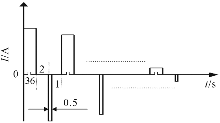
为简化电路设计,降低控制难度,本设计采用充电36 s,间歇2 s,反向放电0.5 s,再间歇1 s的周期循环脉冲充电,充电电流可表示为:
| $ {I_{\rm{c}}} = 22 \times {{\rm{e}}^{-2 \times \left( {t + 0.01} \right)}} $ | (16) |
采用的脉冲充电电流如图 7所示。
|
| 图 7 脉冲充电电流 Fig.7 Pulse charging current |
3) 恒压充电。
当电池组SOC估算值大于80%时,由于脉冲电流非常小,充电电路和电流控制难以实现小脉冲电流,所以采用恒压充电,进行电流自动调节。本设计采用100节11 Ah/3.2 V磷酸锂铁串联而成的电池组,充电上限为400 V,此阶段采用384 V电压充电,直到SOC为100%时停止充电。
综上所述,三段式智能充电过程中电流示意图如图 8所示。
|
| 图 8 三段式智能充电电流 Fig.8 Three-stage intelligent charging current |
根据三段式智能充电方式所设定小电流为1.1 A,脉冲充电公式(16),以及恒定电压,建立智能充电仿真模型,如图 9所示。

|
| 图 9 智能充电仿真模型 Fig.9 Intelligent charging simulation model |
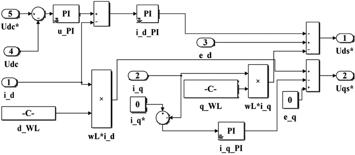
采用双环控制即电流内环电压外环控制,既能控制直流母线电压,又能保证内环电流的快速跟踪[16-17],如图 10所示。
|
| 图 10 电流内环电压外环仿真模型 Fig.10 Current inner loop and voltage outer loop simulation model |
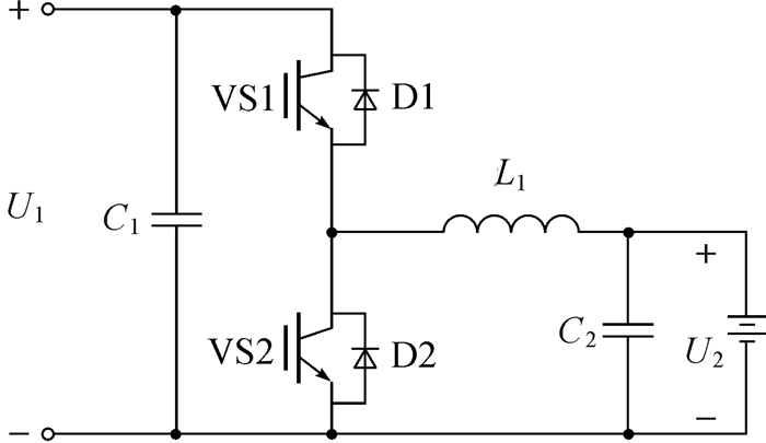
采用双向半桥拓扑结构,通过控制IGBT的开关实现能量的双向传输,实际为升降压Boost/Buck电路[18],如图 11所示。
|
| 图 11 DC/DC双向半桥型拓扑结构 Fig.11 DC/DC bidirectional half bridge topology structure |
充电过程中电压调节采用电压外环电流内环的闭环PI调节,电流调节采用电流环PI调节,经PI调节后得到不同占空比,以其控制DC/DC双向电路中IGBT的通断得到不同的电压和电流[19]。
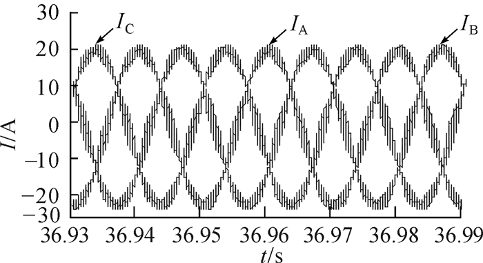
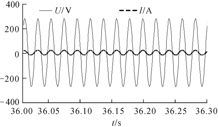
3.3 结果分析图 12为PWM整流交流侧三相稳态电流,表明智能充电系统交流侧按照正弦波变化。交流侧电压和电流同相,功率因素接近1,图 13为PWM整流交流侧A相电压和电流。
|
| 图 12 PWM整流交流侧三相稳态电流 Fig.12 Three phase steady state current for PWM rectifier AC side |
|
| 图 13 PWM整流交流侧A相电压和电流 Fig.13 A phase voltage and current for PWM rectifier AC side |
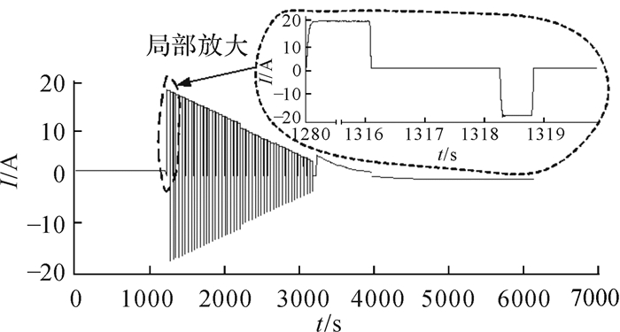
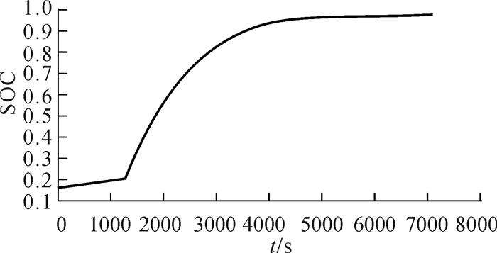
由图 14、图 15仿真结果可知,在初始SOC值设置为15%时,进行0.1C恒定电流(1.1 A)小电流充电,SOC值缓慢上升,可以避免电池因SOC值过低时大电流充电造成的电池损伤。
|
| 图 14 三段式智能充电系统电流与时间关系曲线 Fig.14 The relationship between current and time for the three-stage intelligent charging system |
|
| 图 15 三阶段智能充电系统SOC值与时间关系曲线 Fig.15 The relationship between SOC value and time for the three phase intelligent charging system |
当SOC值达到20%时,转为脉冲充电。此阶段采用39.5 s的周期循环脉冲充电,此阶段SOC增加比较快,充电快速。
当蓄电池SOC值达到80%时,采用1.2倍额定电压值(384 V)对蓄电池进行恒压充电。随着充电时间增加,充电电流由大电流逐渐减为小电流,SOC值上升速度减缓,有利于减少电池自身放热,使蓄电池内部化学反应更加平稳。
4 结论针对汽车蓄电池快速充电的问题,结合传统能量守恒法与马斯定理,提出基于改进型能量守恒SOC估算法的三段式智能充电方式,并进行仿真分析。
1) 考虑电池容量衰减和自身能量损耗对SOC估算的影响,提出了改进型能量守恒SOC估算法,并与传统能量守恒法进行对比分析,验证其准确性。
2) 针对传统充电方式的不足,提出了基于改进型能量守恒SOC估算的三段式智能充电方式,即小电流充电、脉冲充电、恒压充电。
3) 建立了三段式智能充电仿真模型,进行了仿真分析,验证了改进型能量守恒SOC估算法与三段式智能充电方式的安全性、快速性。
| [1] |
王金勇.
蓄电池几种充电方法的优劣[J]. 设备管理与维修, 2003(4): 35–39.
WANG Jin-yong. Advantages and disadvantage of several methods of charging battery[J]. Plant Maintenance Engineering, 2003(4): 35–39. |
| [2] | PASCAL Venet, MICHAEL Millet, JENS Groot. Impact of periodic current pulses on Li-ion battery performance[J]. IEEE Transactions on Industrial Electronics, 2012, 59(9): 3481–3488. DOI:10.1109/TIE.2011.2172172 |
| [3] |
李敬兆. 采用神经网络预测和变结构模糊控制的铅酸蓄电池最优充电技术研究[D]. 合肥: 合肥工业大学电气与自动化工程学院, 2003: 19-57.
LI Jing-zhao. Study on the optimal leaded charging with neural network panda variable structure fuzzy [D]. Hefei: Hefei University of Technology, School of Electrical Engineering and Automation, 2003: 19-57. |
| [4] |
文锋, 姜久春, 张维戈, 等.
电动汽车用锂离子电池组充电方法[J]. 汽车工程, 2008, 30(9): 792–795.
WEN Feng, JIANG Jiu-chun, ZHANG Wei-ge, et al. Charging method for Li-ion battery pack in electric vehicles[J]. Automotive Engineering, 2008, 30(9): 792–795. |
| [5] |
刘玉杰, 姜印平, 孟祥适.
关于快速脉冲充电技术的研究[J]. 蓄电池, 2004, 41(2): 71–73.
LIU Yu-jie, JIANG Yin-ping, MENG Xiang-shi. Study on fast pulse recovery based on PIC single chip[J]. Chinese Labatt Man, 2004, 41(2): 71–73. |
| [6] |
姚雷, 王震坡.
锂离子动力电池充电方式的研究[J]. 汽车工程, 2015, 37(1): 72–77.
YAO Lei, WANG Zhen-po. A research on the charging protocols of Lithium-ion tractio battery[J]. Automotive Engineering, 2015, 37(1): 72–77. |
| [7] |
王鸿雁, 李广凯, 江政昕.
锂离子电池快速充电方法研究[J]. 电源技术, 2012, 36(11): 1616–1619.
WANG Hong-yan, LI Guang-kai, JIANG Zheng-xin. Research on fast charge method for lithium ion battery[J]. Chinese Journal of Power Sources, 2012, 36(11): 1616–1619. DOI:10.3969/j.issn.1002-087X.2012.11.008 |
| [8] |
陈浩. UPS中铅酸电池的快速、安全充电方式的探讨[D]. 上海: 复旦大学信息科学与工程学院, 2005: 11-21.
CHEN Hao. Discussion on fast and safe charging of lead acid battery in UPS[D]. Shanghai: Fudan University, School of Information Science and Technology, 2005: 11-21. |
| [9] |
胡明辉, 秦大同.
混合动力汽车电池管理系统SOC的评价[J]. 重庆大学学报(自然科学版), 2003, 26(4): 20–23.
HU Ming-hui, QIN Da-tong. SOC definition of battery management system used in hybrid vehicles[J]. Journal of Chongqing University (Natural Science Edition), 2003, 26(4): 20–23. |
| [10] |
李哲, 仝猛, 卢兰光, 等.
动力型铅酸电池及LiFe PO4锂离子电池的容量特性[J]. 电池, 2009, 39(1): 26–28.
LI Zhe, TONG Meng, LU Lan-guang., et al. Capacity characteristics of power lead-acid and LiFePO4 Li-ion batteries[J]. Battery Bimonthly, 2009, 39(1): 26–28. |
| [11] | GEING Kevin L, SAZHIN Serfiy V, JAMISON David K, et al. Investigation of path dependence in commercial Lithium-ion cells chosen for pulg-in hybrid vehicle duty cycle protocols[J]. Journal of Power Source, 2011, 196(7): 3385–3403. |
| [12] |
李哲, 韩雪冰, 卢兰光, 等.
动力型磷酸铁锂电池的温度特性[J]. 机械工程学报, 2011, 47(18): 115–120.
LI Zhe, HAN Xue-bing, LU Lan-guang, et al. Temperature characteristics of power LiFePO4[J]. Journal of Mechanical Engineering, 2011, 47(18): 115–120. |
| [13] |
董波. LiFePO4动力电池组放电末端SOC估计研究[D]. 合肥: 合肥工业大学机械工程学院, 2015: 24-61.
DONG Bo. Study on the end of SOC estimation of LiFePO4 battery pack[D]. Hefei: Hefei University of Technology, School of Mechanical Engineering, 2015: 24-61. |
| [14] |
闫怀义, 王迎进.
Arrhenius经验公式的推导及Ea的本质[J]. 绍兴文理学院学报(自然科学版), 2010, 30(8): 12–14.
YAN Huai-yi, WANG Ying-jin. The derivation of Arrhenius empirical formula and the essence of Ea[J]. Journal of Shaoxing University (Natural Science), 2010, 30(8): 12–14. |
| [15] |
熊刚. 车用锂离子电池SOC和电池容量估算研究[D]. 长沙: 中南大学信息科学与工程学院, 2014: 20-43.
XIONG Gang. Research on SOC and capacity estimation of Lithium-ion battery for electric vehicle [D]. Changsha: Central South University, School of Information Science and Engineering, 2014: 20-43. |
| [16] | WING-Chi So, CHIK Tsc, YIM Shu Lee. Development of a fuzzy logic controller for DC/DC converters: design, computer, simulation, and experimental evaluation[J]. IEEE Transactions Power Electronics, 1996, 11(1): 24–31. DOI:10.1109/63.484413 |
| [17] |
万健如, 宫成, 李昆鹏.
电压型PWM整流器预测直接电容功率控制研究[J]. 电力系统保护与控制, 2013, 41(3): 96–101.
WAN Jian-ru, GONG Cheng, LI Kun-peng. Research on predict direct capacitor power control of voltage source PWM rectifier[J]. Power System Protection and Control, 2013, 41(3): 96–101. DOI:10.7667/j.issn.1674-3415.2013.03.017 |
| [18] |
王立欣, 靳刚, 程树康.
混合动力车用PWM整流器控制方法的研究[J]. 电机与控制学报, 2005, 9(2): 199–202.
WANG Li-xin, JIN Gang, CHENG Shu-kang. The study of PWM rectifier control method in hybrid electric vehicle[J]. Electric Machines and Control, 2005, 9(2): 199–202. |
| [19] |
张亚娟, 蒋久春, 牛利勇.
电池测试设备用多重双向DC/DC变换器的研究[J]. 电测与仪表, 2011, 48(7): 69–74.
ZHANG Ya-juan, JIANG Jiu-chun, NIU Li-yong. The research of multiple Bi DC/DC H-Bridge converters[J]. Electrical Measurement & Instrumentation, 2011, 48(7): 69–74. |


