 2013, Vol. 1
The article information
- P. Bhargava, C. P. Paul, C. H. Premsingh, S. K. Mishra, Atul Kumar, D. C. Nagpure, Gurvinderjit Singh, L. M. Kukreja
- Tandem rapid manufacturing of Inconel-625 using laser assisted and plasma transferred arc depositions
- Advances in Manufacturing, 2013, 1(4): 305-313
- http://dx.doi.org/10.1007/s40436-013-0044-z
-
Article history
- Received: 2013-03-10
- Accepted: 2013-10-16
- Published online: 2013-11-30


2.Laser Materials Development and Devices Division, Raja Ramanna Centre for Advanced Technology, Indore 452 013, India
During the past decade, there has been a growing interest in laser based layered manufacturing process, popularly known as laser rapid manufacturing (LRM), for the development of new products and repair of prime components. The process has various advantages over the conventional techniques in terms of reduced cycle time, no specific fixtures and tooling, broader availability of materials for specific application with configurable manufacturing and tailored properties. LRM processes became important because it provided the customized products to address dynamic consumer market, leverage competitive advantage against competitors in product development and improve quality of life by biomedical solutions [1, 2]. Plasma transferred arc (PTA) deposition has been used for deposition of bulk materials for repair of dies and mold, in situ repair of worn-out prime components and surfaces with improved tribological properties [3]. In general, LRM has advantages on dimensional accuracy, improved mechanical properties, finer process control, reduced heat input and lower thermal distortion [4, 5, 6, 7, 8], while PTA has good performance in terms of lower initial investment, lower running cost and higher deposition rate [9, 10, 11]. To quantify the clubbed advantages and limitations of both processes (LRM ? PTA), a comprehensive investigation was carried out by the deposition of Inconel-625 using these processes individually or in tandem. The effect of various processing parameters, such as input power (laser/ plasma), scan speed and powder feed rate on deposition, was investigated. The process parameter windows for both deposition processes were identified. The microstructure and mechanical properties of the deposits were also studied. The interface strength of the deposits was investigated using the adhesion-cohesion testing. 2 Material
Inconel-625 is one of the nickel-chromium based alloys, which is widely used for various naval, aerospace and nuclear applications. It has outstanding fatigue and thermal- fatigue strength; good oxidation and corrosion resistance; excellent resistance to chloride stress corrosion cracking; pitting resistance at elevated temperature; and excellent brazing and welding ability [12, 13]. It derives its strength from the stiffening effect of molybdenum and niobium on its nickel-chromium matrix, thus precipitationhardening treatments are not required. Nickel and chromium provide resistance to oxidizing environment, while nickel and molybdenum to non-oxidizing environment. Pitting and crevice corrosion are prevented by molybdenum. Niobium stabilizes the alloy against sensitization during welding. Inconel-625 is an alloy with many ongoing and potential applications in engineering practice such as heat shields, furnace hardware, gas turbine engine ducting, combustion liners, spray bars, chemical plant hardware and specific seawater components [12]. Hence, Inconel-625 was chosen in the present study. The size of the powder particles used in the study was in the range from 45 μm to 106 μm. The chemical composition of Inconel-625 is presented in Table 1.

The LRM and PTA material deposition were carried on type 316L stainless steel substrates, and each was 75 mm in diameter and 12 mm in thickness. The LRM setup (see Fig. 1) consisted of an indigenously developed 3.5 kW continuous wave CO2 laser system [14], a co-axial powderfeeding nozzle with a volumetric controlled powder feeder as described earlier [1], and a five axis CNC laser workstation which is similar to that mentioned in earlier report [2]. The CO2 laser beam was transferred to 5-axis CNC laser workstation by steering the beam with the watercooled gold coated plane copper mirrors. A concave mirror (radius of curvature is 600 mm) at an inclination angle about 22° was used to focus laser beam at the laser workstation, and a defocused beam of diameter about 1.2 mm was delivered at the fabrication point for LRM. The PTA deposition setup (see Fig. 2) consisted of a PTA source and a 3-phase, 415 V, 50 Hz power supply with output voltage in the range of 75-85 V DC and discharge current in the range of 0.4-20 nm. The argon gas was used for both plasma generation and shielding with a gas flow rate of 1.5 L/min and 7.5 L/min respectively. The standoff distance between plasma torch and work piece was 8 mm throughout the experiment.
 |
| Fig. 1 Schematic arrangement of the LRM system |
 |
| Fig. 2 Schematic arrangement of PTA assisted material deposition setup |
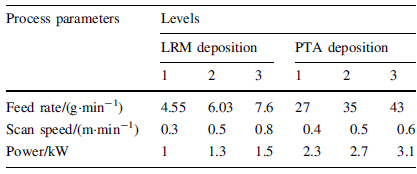
A number of tracks were laid at different sets of processing parameters to identify the process window for continuous and uniform tracks in both processes. Comprehensive experiments were planned as per standard orthogonal L9 array to investigate the effects of power (laser and plasma), scan speed and powder feed rate on the deposition on Inconel-625 samples. Table 2 presents the control factors and their levels used in the experiments for LRM and PTA depositions. The deposited tracks were examined and the optimum process parameters were deduced. These optimum parameters were used for bulk deposition using multi-layer overlapped tracks. These multi-layer overlapped track deposits were used to shape specimens for various mechanical and metallurgical characterizations.
The surface and sub-surface defects in depositing were examined using dye-penetrant tests and ultrasonic testing. The qualified samples were cut, epoxy mounted, ground and polished for microscopic studies. The microscopic studies were carried out using optical microscopes (Make: Nissho Optical TZ-240, and Olympus PME3) and scanning electron microscope (Philips XL30). The tensile test was conducted on the standard sub-size specimen as per ASTM E8. Tensile specimens of 32 mm gauge length and 4 mm thickness were prepared from the deposits of LRM and PTA with orientation of tensile loading parallel/perpendicular to the track deposition direction. The specimen was tested using 150 kN servo hydraulic controlled universal testing machine. The Charpy impact test with a V-notch specimen was carried out at room temperature to evaluate the impact resistance of the material against stress concentration at the change of the section. The adhesion cohesion test was performed using 150 kN servo hydraulic controlled universal testing machine for evaluating the strength of the interface between LRM and PTA deposits.
To estimate the effect of the direction of material deposition on material properties, the specimens were extracted from two orthogonal directions and they were named as 0° and 90°. The 0° referred to the specimen extracted in such a way that the tensile loading axis was parallel to the direction of deposition, while 90° referred to the specimen with the tensile loading axis perpendicular to the direction of deposition. The direction 0° and 90° of deposits in relative to the tensile loading axis are presented in Figs. 3a, 3b. The direction of material deposition was also referred to as rastering pattern. Vickers micro hardness measurement was performed on the cross-section of laser and PTA assisted deposits using Leitz Mini load-2 micro hardness tester with a load of 100 g, as per ASTM standard. The micro hardness was measured along transverse direction of deposits.
 |
| Fig. 3 Direction 0° and 90°of deposits in relative to the tensile loading axis |
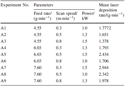
A set of experiments was carried out as per L9 orthogonal array and a number of tracks were deposited. The width and height of the tracks were measured at least at three locations to calculate the deposition rate. The deposits were also examined for visual, macro and micro examination. The set of process parameters which yielded regular and continuous tracks with the highest deposition rate were selected for bulk deposition in both processes. The mean material deposition rate for each experiment was calculated from the experimental results. Tables 3 and 4 summarize the mean deposition rate for both the material deposition processes, as per L9 array.

It was observed that the laser power density in the range of 30-60 kW/cm2 was primarily required for successful track deposition at powder feed rate of 4-8 g/min and scan speed of 0.3-0.8 m/min for LRM. When the laser power density dropped below the specified range, discontinuous tracks with non-uniform cross section were observed. On the other hand, excessive melting of substrate/pre-deposited layer was observed, when the laser power density went above the specified range. A similar trend was observed for multi-layer single track and multi-layer overlapped track depositions. This is in agreement with the earlier observation made by Paul et al. [15, 16]. The deposition trails of the Inconel-625 with PTA at various sets of processing parameters revealed that the discharge power in the range of 1.8-3.5 kW was essentially required for successful deposition with powder feed rate of 20-52 g/min and scan speed of 0.3-0.7 m/min. The discharge power governed the heat energy input and had significant effects on dilution and area of deposit per unit length. As the discharge current increased, there was an increase in the area of deposit up to certain value, and whereafter it decreased. It was due to increased dilution in the substrate.
The scan speed affected the input energy per unit traverse length and powder fed per unit traverse length for both processes, as it was directly related to the interaction time. The increase in scan speed resulted in reduced deposition rate, as the input energy per unit traverse length and powder fed per unit traverse length were decreased. It was observed that the deposition rate increased linearly with the increase in powder feed rate up to a critical value for a given powder density and a given interaction time in the case of single-track deposition using LRM, and thereafter the track did not adhere to the substrate. The observed critical value for LRM deposition was found to be about 12 g/min in our experimental setup. The above observation is primarily due to the fact that the powder flux shielded the laser beam and caused insufficient substrate melting at higher powder feed rate. For PTA deposition, an increase in powder feed rate results in increased deposition till the available discharge power became insufficient to melt and deposit the fed powder. It was observed that the melting of thin layer of the substrate for achieving good metallurgical bond arose from the energy transfer from the molten metal falling on the substrate. High PTA power resulted in high heat input, which yielded discontinuous and porous deposits with high dilution, while low PTA power resulted in porous deposits with very little dilution. The lower and upper limits of material feed rate for PTA deposition in the present setup were 27 g/min and 60 g/min respectively. 4.3 Microscopic examination
The LRM and PTA deposits were cut along both the transverse and the longitudinal cross-sections, polished and etched for macro- and micro-structural examinations. Few pores at the isolated locations were observed in the LRM deposits. These pores may be due to trapped gas. The microstructure examinations of LRM deposits of Inconel- 625 revealed that there were finely intermixed dendritic and cellular microstructures with high dislocation density. Figure 4a presents typical microstructure observed in LRM deposits of Inconel-625. The direction of dendrite growth was along the direction of deposition [17]. The fine dendrite formation was due to inherent rapid cooling rate during laser assisted material deposition, while cellular microstructure was attributed to relatively slower cooling rate during multi-layer deposition. The microscopic studies of PTA deposits revealed that columnar dendrite were observed in deposits. The deposit was free from any specific macro defects. The type and size of microstructure depended on substrate conditions and solidification rate. Substrate conditions with faster cooling rate led to the formation of finer microstructure. This was in agreement with the observations made by Ahn et al. [18]. For microstructure formation at higher heat input, the influence of substrate conditions was predominated by the processing parameters. Figure 4b presents the typical microstructure observed in PTA deposited Inconel-625 samples. The etched transverse cross sections of deposit revealed the directional solidified microstructure. For hybrid mode of material deposition, LRM and PTA processes were used to deposit material in successive tracks and the interface was also studied. Figure 4c presents the microstructure of the deposit in tandem mode. Two distinct microstructures were observed in the regions deposited with different processes. The coarser columnar dendritic structure was observed in the region of PTA deposits while mixed columnar and cellular dendrites were observed in the region of laser deposits. This difference in the microstructure was primarily due to different cooling rates during LRM and PTA deposition. No visible defect was detected at the interface of these deposits. This difference in the microstructure was likely to result in different mechanical properties of deposits depending upon the regions of deposited material, as shown in Fig. 4c. Figures 5a, 5b present the typical microstructure observed in LRM and PTA deposited Inconel-625 samples. It revealed the pattern of layer-bylayer deposition. No sign of oxidation was observed between the layers and within the tracks. The solidification originated from the substrate which acted as a heat sink. Columnar grain (dendrites) growed parallel to the direction toward the free surface of the deposit. This is in agreement to the observations made by Yao et al. [19]. The microscopic examination revealed defect free deposits without any material flaw or crack. The microstructure of PTA deposits also revealed breaking of dendrite arm and remelting due to stirring of melt pool [3]. XRD results showed no significant difference in LRM and PTA deposits.
 |
| Fig. 4 Different mechanical properties of deposits depending upon the regions of deposited material a typical microstructure of LRM deposit, b typical microstructure of PTA deposit, c microstructure at interface of two deposits |
Dye penetrant (DP) testing of the LRM and PTA deposited Inconel-625 material was carried out to detect surface defects, like- surface porosity, cracks, etc. No surface defect could be detected using DP test. The samples were also subjected to ultrasonic testing at 10 MHz using normal probe reflection method to detect subsurface defects. No defects were revealed in the deposits. The surface properties of LRM and PTA deposits were characterized. The measured average surface finish by comparing all the peaks and valleys to the mean line (CLA) value for LRM deposits was from 5 μm to 7 μm, while it was from 100 μm to 150 μm for PTA deposits. The measured dimensional accuracy of deposition for LRM and PTA deposits were greater than 350 μm and 1, 200 μm respectively. These observations indicated that LRM might be deployed for making boundary surfaces, whereas bulk deposition might be done using PTA. The deployment of these two processes led to a dimensional accuracy close to 500 μm.
Figure 6 presents a typical stress-strain curve obtained in tensile testing of laser and PTA deposited Inconel-625 samples. The stress-strain curve did not exhibit distinct yield points, and there was gradual change in slope of tensile curve in elastic-plastic zone. Such behavior was primarily observed in FCC materials [20]. The value of 0.2% yield strength obtained from stress-strain curve was almost same, hence the limit of workable elastic behavior of a material was the same for both LRM and PTA specimens. The fracture of test specimens took place without noticeable necking. This trend was generally observed in cold worked or work hardened condition [20]. Strain of both LRM and PTA deposits confirmed the ductile behavior in deposits. Further, the rastering pattern used for the material deposition did not influence the tensile properties of the material for LRM with overlapping error bar for different rastering patterns. However, Inconel-625 deposited using PTA process indicated anisotropy in the mechanical properties due to the formed microstructures. As compared to conventionally processed Inconel-625 [16], LRM deposited material exhibited improved tensile properties without reduction in percentage elongation while PTA deposited material exhibited comparable tensile strength with slight reduction in percentage elongation. Similar tensile results were obtained by Xu et al. [3]. However, 12%, 25% strain was obtained for ductility varies due to operation mode of plasma source which resulted in different cooling rate in deposition process. The maximum variation in 0.2% yield strength for both the deposits was found to be 20%.
 |
| Fig. 5 Multi-layer overlapped tracks of a LRM and b PTA assisted material deposition |
 |
| Fig. 6 Typical stress-strain curve of laser and PTA deposited Inconel-625 |
To evaluate the hardness of the deposited materials, the Rockwell hardness test was carried out as per ASTM E18. The hardness of LRM and PTA deposited materials was in the range of 46-52 HRc and 37-42 HRc respectively, while that of solution annealed was 27 HRc. The higher hardness in LRM and PTA deposited materials was due to rapid cooling rate during processing, which resulted in finer grain structure. The observation was confirmed through a post annealing treatment of the deposited samples, in which the hardness value was brought down to the range of 29-30 HRc. Hardness profile of hybrid deposition with two successive deposition processes was also carried out. The observed hardness of the deposits without annealing was presented in Fig. 7. A zig-zag pattern was observed in microhardness values in PTA deposits. This pattern might be due to larger phase of carbides (primarily MC and M6C), which were inherently present in Inconel-625 alloy [12]. It was well known that the total heat input in laser assisted processes (like LRM) was significantly less than that in PTA processes due to associated high energy density in case of laser processing. This higher energy density resulted in steep thermal gradient and subsequent faster cooling rate in the materials subjected to laser processing. On the contrary, relatively slower cooling rate was seen during PTA processes. This slower cooling rate was the cause of the larger phases of carbides (primarily MC and M6C) in PTA processed samples. It was also evident in Fig. 7 in the form of larger columnar dendritic structures in the sections of PTA deposited samples.
 |
| Fig. 7 Hardness profile observed in hybrid deposition |
The adhesion strength of coatings was generally evaluated by a tensile adhesion test in which procedure defined in ASTM C633-79. However the test procedure governed the use of adhesive material for joining jig with coated surface, therefore the measurable strength limited the strength of the adhesive. Paul et al. [21] conducted adhesion cohesion test for evaluating bond strength between WC-Co clad layers. Similar procedure was adopted for evaluating the cohesive strength between LRM and PTA layers. In this test, a square of 30 mm × 30 mm and 15 mm thickness was cladded with about 3 mm thick LRM cladding and 12 mm thick PTA cladding layers. Then, the samples were prepared as shown in Fig. 8a. The strength was determined by compressive testing of the specimen using the universal testing machine, as shown in Fig. 8b.
 |
| Fig. 8 Sample for cohesive/adhesive strength compressive testing of the specimen |
Figure 9 depicts a typical load-displacement curve of the adhesion-cohesion test. The displacement was converted from the cross-head displacement rate, thus the loaddisplacement curve had lower slope at the beginning due to compliance of loading system, and later the curve became linear with a sharper slope. It was observed in the curve that the cladding broke at the peak stress rather than no sudden fall of the load values. It was because the fractured surface resisted the movement of the punch and leaded to an apparent material resistance, even after the material failure. Observations after testing revealed that the fracture occurred at the interface. The failure was mostly at the interface. Before failure a displacement of about 2.5 mm was observed, indicating that the nature of interface was more towards ductile. The interface strength of tandem deposition was evaluated employing adhesion-cohesion test and the strength was found to be (325 ± 35) MPa.
 |
| Fig. 9 Typical load-displacement curve obtained from adhesioncohesion test |
The Charpy impact test with a V-notch specimen was carried out at room temperature as per ASTM E23 to get an indication of the impact resistance of the material against stress concentration at the change of the section. This would also indicate the resistance of material against the crack propagation, once a crack was observed in the material. Results of Charpy impact test were presented in Fig. 10. The test results revealed that the impact resistance of laser processed material for 0° and 90° rastering pattern was (102 ± 5) J and (100 ± 3) J, respectively. The obtained impact resistance was at par with that of conventionally processed material, while the impact resistance of PTA deposited material for 0° and 90° rastering pattern was (85 ± 3) J and (90 ± 4) J, respectively. The results revealed that the impact strength for LRM and PTA deposits were found to be within ±15%. The fractographs (see Figs. 11a, 11b) of the impact testing samples confirmed that the shear lip was formed before the failure during impact testing, and it was clearly visible on the fracture surface indicating ductile nature of the fracture.
 |
| Fig. 10 Results of Charpy V-notch impact testing |
 |
| Fig. 11 Fractograph of a laser b PTA deposited Inconel-625 after Charpy V-notch impact testing |
The effects of various processing parameters on the deposition rate were investigated for the material deposition using LRM and PTA processes individually or in tandem configuration. It was found that the maximum deposition rates were 12 g/min and 60 g/min for LRM and PTA process, respectively. Dye penetrant and ultrasonic testing did not find any surface and sub-surface defects in the deposits. The mechanical properties of deposits were investigated for potential application in hybrid manufacturing mode. Almost same mechanical properties with ±20% variation were achieved. The measured surface finish (CLA) value for laser deposits was from 5 μm to 7 μm and for PTA deposits was from 100 μm to 150 μm. The deployment of both processes in tandem led to a dimensional accuracy close to 500 μm. The microstructural studies revealed mixed dendritic-cellular and dendritic microstructures in laser and PTA deposited samples, respectively. The sample produced in tandem configuration revealed different microstructures for different processes with distinct interface in between them. The interface strength was found to be (325 ± 35) MPa. The study confirmed the deployment feasibility of two processes in tandem for potential hybrid mode of material deposition involving LRM and PTA.
Acknowledgment The authors acknowledge the help of team members of Laser Material Processing Division in carrying out the experimental work.| 1. | Paul CP, Bhargava P, Kumar A et al (2012) Laser rapid manufacturing: technology, applications, modeling and future prospects. In: Paulo Davim J (ed) Lasers in manufacturing. Wiley, London, pp 1-67 |
| 2. | Kukreja LM, Kaul R, Paul CP et al (2013) Emerging laser materials processing techniques for future industrial applications. In: Majumdar JD, Manna I (eds) Laser-assisted fabrication of materials, vol 161. Springer, New York, pp 423-478 |
| 3. | Xu F, Lv Y, Liu Y et al (2013) Microstructural evolution and mechanical properties of Inconel-625 alloy during pulsed plasma arc deposition process. Mater Sci Technol. doi:10.1016/j.jmst.2013.02.010 |
| 4. | Paul CP, Jain A, Ganesh P et al (2006) Laser rapid manufacturing of Colmonoy-6 components. Opt Lasers Eng 44:1096-1109 |
| 5. | Song L, Singh VB, Dutta B et al (2011) Control of melt pool temperature and deposition height during direct metal deposition process. Int J Manuf Technol. doi:10.1007/s00170-011-3395-2 |
| 6. | Moat RJ, Pinkerton A, Li L et al (2009) Crystallographic texture and microstructure of pulsed diode laser-deposited Waspaloy. Acta Mater 5:1220-1229 |
| 7. | Nowotny S, Scharek S, Beyer E et al (2007) Laser beam build-up welding: precision in repair, surface cladding, and direct 3D metal deposition. J Therm Spray Technol 16:344-348 |
| 8. | Imran MK, Masood SH Brandt M (2010) Bimetallic dies with direct metal-deposited steel on Moldmax for high-pressure die casting application. Int J Adv Manuf Technol 52:855-863 |
| 9. | d'Oliveira ASCM, Vilar R, Feder CG (2002) High temperature behavior of plasma transferred arc and laser Co-based alloy coatings. Appl Surf Sci 201:154-160 |
| 10. | Gatto A, Bassoli E, Fornari M (2004) Plasma transferred arc deposition of powdered high performances alloys: process parameters optimization as a function of alloy and geometrical configuration. Surf Coat Technol 187:265-271 |
| 11. | Zhao W, Liu L (2006) Structural characterization of Ni-based superalloy manufactured by plasma transferred arc-assisted deposition. Surf Coat Technol 201:1783-1787 |
| 12. | http://www.specialmetals.com/documents/Inconel%20alloy%206 25.pdf. Accessed 5 Sept 2013 |
| 13. | Thivillon L, Bertrand LP, Laget B et al (2009) Potential of direct metal deposition technology for manufacturing thick functionally graded coatings and parts for reactors components. J Nucl Mater 385:236-241 |
| 14. | Nath AK, Reghu T, Paul CP et al (2005) High-power transverse flow CW CO2 laser for material processing applications. Opt Laser Technol 37:329-333 |
| 15. | Paul CP, Negi J, Nath AK (2002) Parametric dependence and fabrication time in laser rapid manufacturing. Met Mater Process 14(3):2163-2172 |
| 16. | Paul CP, Ganesh P, Mishra SK et al (2007) Investigating laser rapid manufacturing for Inconel-625 components. Opt Laser Technol 39:800-805 |
| 17. | Dinda GP, Dasgupta AK, Majumder J (2009) Laser aided direct metal deposition of Inconel-625 superalloy: microstructural evolution and thermal stability. Mater Sci Eng A 509:98-104 |
| 18. | Ahn Y, Yoon B, Kim H et al (2002) Effect of dilution on the behavior of solidification cracking in PTAW overlay deposit on Ni-base superalloys. Met Mater Int 8:469-477 |
| 19. | Lv YH, Liu YX, Xu FJ et al (2013) Plasma transferred arc forming technology for remanufacture. Adv Manuf. doi:10.1007/ s40436-013-0017-2 |
| 20. | Bhargava AK, Sharma CP (2011) Mechanical behavior and testing of materials. PHI Learning Pvt Limited, New Delhi |
| 21. | Paul CP, Alemohammad H, Toyserkani E et al (2007) Cladding of WC-12 Co on low carbon steel using a pulsed Nd: YAG laser. Mater Sci Eng A 464(1):170-176 |