 2013, Vol. 1
The article information
- Feng-Feng Xi, Lin Yu, Xiao-Wei Tu
- Framework on robotic percussive riveting for aircraft assembly automation
- Advances in Manufacturing, 2013, 1(2): 112–122
- http://dx.doi.org/10.1007/s40436-013-0014-5
-
Article history
- Received: 2012-12-23
- Accepted: 2013-02-23
- Published online: 2013-04-06


2. Robotic and Automation Center, Shanghai University, Shanghai 200072, People's Republic of China
3. Department of Automation and Instruments, Shanghai University, Shanghai 200072, People’s Republic of China
Riveting and welding represent two primary joining methods for the assembly of structural components that require strong joint strength. Compared with welding mainly a fusion method, riveting a mechanical method generates no thermal deformation, hence widely used for joining high thermal conductive materials such as aluminum sheet metals used in aircraft assembly [1]. There are hundred thousands of rivets in a regional aircraft and millions in a large continental aircraft. Overall, the operation of aircraft assembly is divided into three stages: subcomponent assembly, component assembly, and line assembly. The subcomponent assembly is the first step to construct the base components for four major sections, namely, fuselage, wing, cockpit and empennage. The component assembly is the middle step to join the subcomponents to form an individual major section. The line assembly is the last step to assemble a whole aircraft by connecting the four major sections together.
The current riveting process in aerospace manufacturing entails a mix of manual riveting, semi-automated riveting, and automated riveting. The semi-automated and automated riveting machines are widely used in North America and Europe, but only limited to component assembly, such as wing skin panels and fuselage skin panels. Subcomponent assembly and line assembly are still conducted manually. The labor incurred producing these subassemblies/ assemblies amounts to as much as fifty percent of the total cost. Manual riveting operations are tedious, repetitious, prone to error, and likely causing health and ergonomic problems [1].
In principle, there are two riveting methods, the first called squeezing (or one-shot) riveting, where a large upsetting force is applied to deform a rivet instantly. This method requires a large riveter operating under high pressure beyond the yield strength of aluminum rivets in a range over 500 lb force. As shown in Fig. 1a, this type of riveter is made of either a hydraulic cylinder or an electromagnetic piston, very heavy, bulky and usually needing a lift-assisted device if used for manual operation. The automated and semi-automated riveting machines employ this type of riveter; hence they are gigantic and only limited to riveting large, simple and relatively flat components. The second method is called percussive (or hammering) riveting, where a small impulsive force is applied to deform a rivet accumulatively by a series of hits. As shown in Fig. 1b, this method uses a rivet gun in size of a regular hand-held power tool, very compact and light, operating under much lower pressure in a range less than 100 psi, very safe and energy efficient. Manual riveting employs this principle.
 |
| Fig. 1 Various rivet tools a Squeezing riveter: length[2400, weight [50 lbs, b Percussive rivet gun: length <1000 weight <5 lbs, c Cframe rivet tooling |
Research on robotic riveting has been mainly centering on squeezing riveting that utilizes heavy-duty industrial robots of large size ([100 kg payload). In the automotive industry, squeezing robotic riveting systems have been fully developed and commercialized for joining metal parts. This technology is called the robotic self-piercing riveting, in which a C-frame tooling, as shown in Fig. 1c, and is designed to have a squeezing riveter mounted on one end as a punch and the other end serving as a hitting base [2]. This system has been widely used for automotive chassis assembly. The application of robotic technology in aerospace manufacturing has been significantly slower than that in automotive manufacturing [3]. Though not commercially available, squeezing robotic riveting systems have been researched in the past by Boeing [4] and recently by EADS in Germany affiliated with AirBus [5]. In addition, a robotic system has been implemented at Bombardier in Montreal that uses two giant Kuka robots to hold large panels that are riveted on a C-frame squeezing riveting machine [6].
Though adhesives are used to bond composites, riveting remains as a primary method for joining composite panels where there is requirement for strong joint strength and prevention of laminate de-bonding. Automated squeezing riveting systems have been developed by AirBus and Boeing for riveting composite panels of fuselages and wings. As composites are being introduced to replace steels for fabrication of automotive structural parts, robotic riveting will likely take over welding as a primary joining method for the future of automotive industry [7].
By comparison, robotic percussive riveting is much more compact. Not only a much smaller riveting gun is used but also a light/medium-payload industrial robot of small size (<50 kg payload) can be applied. The overall system compactness offers a great advantage that a robotic percussive riveting system is able to access tight and awkward areas that a squeezing robotic riveting system is not able to. This advantage is referred to as good tool accessibility. In this paper, a framework of research is presented to show that the successful implementation of a robot application requires in-depth process research pertinent to the application. 2 Framework overview
Prior to describing the framework, a brief summary of industrial robots is provided as background information. Generally speaking, industrial robots are general-purpose load-carrying motion devices. Common robot specifications include: payload, workspace (reach), speed/acceleration and accuracy (repeatability). Industrial robots are normally classified according to payload as: light-payload (<15 kg), medium payload (<50 kg), large payload (<300 kg), and heavy duty (300-1, 500 kg). While robot workspace is proportional to payload, the rest of specifications are disproportional.
The main structure of industrial robots is serial, though parallel robots are being used in some applications. Serial robots are designed to mimic human arms, often called articulated robot arms. Though various serial robots were studied, only two types have been adopted as the main stream of industrial robots. The first is selective compliant articulated robot arm (SCARA), a 4-axis robot that imitates the movement of a human arm when sit, as shown in Fig. 2a. The primary use of SCARA robots is for electronic component assembly. The second is programmable universal manipulation arm (PUMA), a 6-axis robot that emulates the movement of a human arm when stand, as shown in Fig. 2b. The majority of industrial robots fall under this category. Both types of robot are designed with a decoupling feature between positioning (first 3 axes) and orienting (remaining axes). The positioning of SCARA follows a cylindrical coordinate system, while that of PUMA follows a spherical coordinate system.
 |
| Fig. 2 Two common industrial robots. a 4-axis SCARA robot. b 6-axis PUMA robot |
The initial application of industrial robots was concentrated on pick-and-place applications with grippers as the main tooling. Since then, they have been explored for various manufacturing applications both contact and non-contact. A good example of non-contact robot application is robotic welding, widely practiced in the automotive industry, where a weld gun is used not in contact with the workpiece. A good example of contact robot application is robotic polishing, widely adopted in the automotive and aerospace industry, where a polishing tool is used in contact with the workpiece. The robot companies who sell robots for these applications usually offer add-on modules in the general robot motion planning software. This indicates that the successful implementation of a robot application requires understanding of the process itself and interaction with the robot.
For this reason, we have developed a process planningdriven approach for the development of our robotic percussive riveting system, a new application for aircraft assembly automation. Figure 3 shows the developed robotic percussive riveting system. It includes a 6-DOF industrial robot that replaces the first worker for holding/ moving a percussive rivet gun; a 5-axis computer numerical control (CNC) gantry system that replaces the second worker for holding/moving a bucking bar. The entire riveting process is automated through synchronization between the robot and gantry. Furthermore, the choice of a gantry system instead of a second robot allows it to serve as a jig for mounting sheet metals.
 |
| Fig. 3 Developed robotic percussive riveting system [13] |
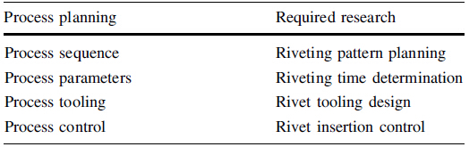
Given that the goal of process planning is to generate a plan in order to successfully produce a product [8], this planning contains a number of key considerations: process sequence, process parameters, process tooling, and process control. As outlined in Table 1, these key considerations are used to guide our research for the purpose of implementing our robotic percussive riveting system. The research methods are described as follows.
Process sequence deals with the steps of a process, which is process specific. Commercial robot planning programs do not provide this feature. Hence, there is a need to study the riveting process. Riveting requires drilling a hole first and then inserting a rivet for fastening. Two riveting processes are exercised in practice, simultaneous and sequential. The first one is to drill and rivet together on a rivet spot, which demands a large tooling to combine a drill and a rivet gun. This process is typically applied on large automated riveting machines where tool accessibility is not of concern for the assembly of large and flat panels. The second process is to drill a series of holes first at the required rivet spots and then switch to a rivet gun for riveting. This process keeps the tooling compact and light, with good tool accessibility for tight and awkward areas, hence is employed for manual operation. Since our system is developed to replace manual operation, the second process is considered here.
In riveting, the required rivet spots are determined by rivet patterns in light of industry standards. For automation, there are two ways to obtain the coordinates of these spots. The first one is to extract from CAD models, as modern aircraft components are designed using CAD. The second way is to compute these spots directly according to rivet patterns. While our development can accommodate both, only the second case is presented here, as the first case is straightforward.
Figure 4 provides a taxonomy of rivet patterns. As depicted in Fig. 5, lap joints are formed by overlapping two pieces of sheet metal, which is asymmetric causing the secondary bending [9]. Butt joints, on the other hand, are created by aligning two pieces of sheet metal to maintain symmetry. Both joints can be laid out in single, double and multiple rows as depicted in Fig. 6. Rivet patterns can be of chain type with rows lined up forming a grid or of zigzag type with rows offset up or down.
 |
| Fig. 4 Taxonomy of rivet patterns |
 |
| Fig. 5 Riveted joints a Lap joint, b Butt joint (single cover), c Joint strength |
 |
| Fig. 6 Rivet rows a Single row, b Double row, c Multiple row |
According to the aerospace standards [10], rivet size should be determined first with respect to the thickness of sheet metals, followed by rivet spacing. Symbolically, rivet size can be expressed as

Rivet spacing is a function of the rivet diameter and the riveting pattern, expressed as

A rivet planning software package has been developed that can compute all the rivet spots based on the abovementioned information. Figure 7 displays two snap shots of the software, with the first showing the animation window and the second showing the rivet spot planning window. Furthermore, this package is being developed to include joint strength analysis. Joint strength is defined as the joint's ability to resist against tension, shear, cleavage and peel, as shown in Fig. 5c. In general, the riveted joint strength is proportional to the number of rows, called joint efficiency [11]. The common failures of the riveted joints are caused by the in-plane force (tension-shear shown in Fig. 6), including breaking of the sheet at the hole section, shearing of the rivet, crushing of the sheet and rivet, and shearing of the hole [10]. Joint strength is also pertinent to the type of joints, symmetric better than asymmetric. Joint strength analysis can be performed using standard stress analysis methods [11] or more advanced finite element methods [12].
 |
| Fig. 7 Developed rivet planning software |
As shown in Fig. 3, in percussive riveting a rivet is placed between a rivet gun and a bucking bar to subject to repetitive impulses from the hammer of the gun. Due to these impacts, the rivet is deformed plastically to join two pieces of sheet metal together. Upon the determination of riveting process sequence, both the robot holding the gun and the gantry holding the bucking bar can be programmed to follow a path specified according to a given rivet pattern and move from spot to spot. However, this program does not know how much time is needed to perform riveting at each spot. Hence, there is a need to study process parameters, which involves riveting process modeling.
The said modeling comprises of two theories, impact dynamics and plasticity [13]. Impact dynamics is applied to model the kinetic energy generated by the percussive gun, and plasticity is applied to model the rivet plastic deformation caused by the impact. As shown in Fig. 8a, a percussive rivet gun is pneumatically driven and composed of a piston and a hammer. Under a compressed air supply, the piston is pushed to drive the hammer to hit the rivet. As illustrated in Fig. 8b, at the start point of the piston stroke, the air pressure on its rear end is higher than that on its front end, so the piston moves forward. As it moves close to the end of its stroke, the pressure difference on the two ends reverses, thereby bringing the piston back. The stroke cycle repeats till the air supply is turned off. The reciprocal of the stroke cycle time is called the triggering frequency. Figure 9 shows a test result of the vibration experiment conducted to establish an empirical relation between the triggering frequency and the supply air pressure.
 |
| Fig. 8 Modeling of a percussive gun [13] a Schematics of a percussive rivet gun, b Impact modeling of a percussive rivet gun |
 |
| Fig. 9 Vibration experiment on percussive rivet gun [13] |
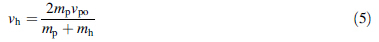
The key in impact dynamics modeling is to determine the hammer velocity hitting the rivet. First, the piston dynamics can be related to the air supply as, without consideration of friction


The hammer velocity is the velocity hitting the rivet which in turns hits the bucking bar. Each hit induces a small rivet plastic deformation and the accumulation of a series of hits results in a large rivet deformation. For this reason, the rivet is discretized into N elements, each modeled as a spring-mass-damper system, as shown in Fig. 10. The spring forces are modeled by a bilinear stress-strain curve containing both elastic and plastic deformation. Consequently, the dynamics comprising the hammer, rivet and bucking bar can be expressed by a set of 2N + 2 first-order nonlinear ordinary differential equations as [13]

where y is a vector representing the displacements of the N elements and the hammer. Note that the bucking bar is fixed, no displacement. Equation (6) can only be solved by computer. The simulation result given in Fig. 11 illustrates how a rivet deforms incrementally under a series of hits.
 |
| Fig. 10 Dynamic modeling of hammer, rivet and bucking bar [13] |
 |
| Fig. 11 Simulation of rivet plastic deformation [13] |
This simulation program is being embedded into the rivet planning software shown in Fig. 7 for the purpose of computing the required rivet time at each rivet spot. At first the required rivet deformation is obtained by calculating the difference between the original rivet length and the thickness of two pieces of sheet metal. Then, the simulation program will run to determine the number of hits needed to produce the required rivet deformation. At last, the required rivet time can be decided by multiplying the number of hits and the time interval of hits (i.e. reciprocal of the triggering frequency). 3.3 Process tooling
Though with rivet path planned and rivet time determined, actual implementation still cannot be guaranteed unless the tool is ensured to do the job. Different riveting methods bring up different issues in tooling design. In the conventional squeezing riveting, a large static force is applied, the main concern being the robot rigidity to withstand the static force. In percussive riveting, however, a series of impulsive (relatively small) forces is applied; the main concern becomes robot vibration. The general guidance of robot tooling design states that the tool should be designed lightweight, in compact size, and with large holding force against vibrations [14]. In other words, the key issue is how to keep the tool small yet strong. Hence, there is a need to study tool design.
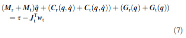
Attachment of a tool to the robot end-effector will change the system kinematics and dynamics.With the tool mounted, kinematic analysis should be carried out with respect to tool center point (TCP) instead of the center point of the endeffector (usually the center point of the mounting plate for the industrial robot). This analysis can be readily accommodated by treating the tooling system as an add-on body in the multibody system of the robot, as shown in Fig. 12. Therefore, the system dynamic equations can be given as [15]
 |
| Fig. 12 Robot system with tooling [15] |
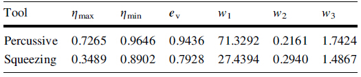
Efforts have been made to relate the system dynamics to the afore-mentioned three considerations of the general guidance, thereby creating a new theory for the tooling design. For this purpose, three new indices are introduced to evaluate the influence of the tooling system on the overall robot system dynamics [15]. The first one, η, is a kinetic energy ratio defined as

The second one, ev, is the robot vibration ratio defined as
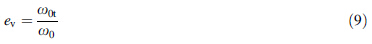
 [15]. Since η is less than 1, the tooling
system will reduce the fundamental natural frequency,
thereby addressing the issue of vibration.
[15]. Since η is less than 1, the tooling
system will reduce the fundamental natural frequency,
thereby addressing the issue of vibration.
The third one is the dynamic manipulability ellipsoid
(DME) that measures the acceleration capability of the tool
tip, thereby addressing the issue of compact size. The
acceleration of TCP can be expressed as at  Assuming that the tool accelerates from rest, i.e.
  , the
TCP acceleration can be related to the joint actuation forces
using Eq. (7) as [15]
, the
TCP acceleration can be related to the joint actuation forces
using Eq. (7) as [15]

In terms of the afore-mentioned three indices, the two tooling designs as shown in Fig. 13 are compared. It can be seen from Table 2 that our tooling design for robotic percussive riveting yields a better performance than the traditional tooling design for automated squeezing riveting, because the index values of the former are overall higher than those of the latter.
 |
| Fig. 13 Comparison of two tooling systems a Percussive b Squeezing |
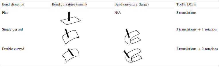
In addition, a part feature-based method has been attempted to map sheet metal part features onto the tool approach direction (TAD). This mapping will not only help further tune the tooling design but also assist in determining correct directions for the tool to have a proper access for drilling and riveting. Generally, aircraft sheet metal parts can be classified in terms of bend direction and curvature. As shown in Table 3, sheet metal parts can be flat, single curved and double curved shapes, each requiring 3, 4 and 5 degrees-of-freedom (DOFs), respectively, in order to position the tool normal to the surface. Though tool's DOFs are identical for both small and large curvatures, tool accessibility is different. The parts with large curvature would have tight spaces, difficult for the tool to access the rivet spot.
Tool accessibility is further affected by the areas surrounding the rivet spot. For this purpose, the taxonomy of a typical airframe assembly is provided in Fig. 14 to look at overall geometric constraints. It is true to say that fuselage and cockpit components involve parts with small curvatures, whereas wing and empennage components involve parts with large curvatures. Airframe is the main body of an aircraft, made of structural members and covered by skins. While bolts are used to join structural members, rivets are used to join skins. In other words, riveting process is mainly associated with aircraft skin assembly that may be divided into 3 steps: skin-stiffening, skin-joint, and skin-to-structure.
 |
| Fig. 14 Taxonomy of airframe assembly |
Skin-stiffening is to provide rigid support to a skin panel by riveting a number of stringers at the back of the panel. There are different shapes of stringer including Z, L, Y, I and hat-shape. Tool accessibility is affected not only by the size and geometry of the stringer but also the spacing between the stringers, as shown in Fig. 15a. Skin-joint is to join skin panels; there are two main joint designs, doubler (symmetric, as shown in Fig. 15b) and splice (asymmetric). Apparently, the size and geometry of the joint will also affect tool accessibility. Skin-to-structure is to mount skin panels onto a structure member, such as wing spar (as shown in Fig. 15c) or fuselage longerons (not shown). Probably, this is the most difficult part of skin assembly as the tool will be confined by the structures. In other words, as the skin assembly steps move up, tool accessibility becomes worsen.
 |
| Fig. 15 Skin assembly. a Skin-stiffening. b Skin-joint. c Skin-tostructure |
Process control is to study control methods for drilling and riveting. There are two main issues pertaining to robotic riveting, localization and visual servoing. Localization is to transfer the coordinates of the rivet spots to those in the robot frame. As shown in Fig. 16, a position sensor system is used to measure both the jig and the rivet gun. By measuring three tooling balls attached to the jig, the jig frame, denoted by sHj, can be determined using a threepoint method [16]. Likewise, by measuring three makers attached to the tool, the tool frame, denoted by sHt, can also be determined. Then the jig frame can be expressed with respect to the tool frame as

 |
| Fig. 16 Localization |
Visual servoing is to control the tool tip to reach each rivet spot precisely based on visual sensing. As mentioned before, the riveting process adopted here is sequential, i.e. drilling all the holes first based on a planned path, and then riveting them along the same path. Though the identical path program is used for both, there are two sources of error needing advanced control for riveting. One is robot repeatability and another hole tolerance. Despite calibration to reduce system errors, industrial robots still exhibit a repeatability problem due to various uncertainties (random errors). For the robot used in our riveting system, it has a path repeatability of 0.6 mm and a position repeatability of 0.2 mm. In general, the hole is drilled with a tolerance of 0.1-0.2 mm bigger than the rivet in diameter. Apparently, the robot repeatability would not be able to guarantee each time the successful insertion of a rivet from the tip of the rivet gun to inside the hole. Unsuccessful rivet insertion would cause damage to sheet metal skins or to the tooling system. For this reason, advanced controls are investigated.
Our control method consists of two parts, one dealing with the insertion path and another dealing with the hole geometry. The first part is to carry out a continuous measurement of tHj based on the afore-mentioned position sensing system; the goal is to keep track of the tool pose in the course of insertion. This is done based on a Kalman filter method [17]

 is a state vector including three variables for the
tool position and other three for the tool orientation; Φk-1
is a state transition matrix; and wk-1 is a noise vector.
Figure 17 shows a simulation result of the relative pose
estimation to demonstrate the effectiveness of the method.
is a state vector including three variables for the
tool position and other three for the tool orientation; Φk-1
is a state transition matrix; and wk-1 is a noise vector.
Figure 17 shows a simulation result of the relative pose
estimation to demonstrate the effectiveness of the method.
 |
| Fig. 17 Kalman filter method—red solid curves represent the nominal values of relative pose; whereas black dash plots represent the estimated values by Kalman filter |
The second part is to determine accurately the position of the hole center in the jig frame, because though the holes are drilled according to a planned path, they will deviate due to various errors. This is a one-time measurement using a highresolution camera mounted on the CNC gantry. Efforts have been devoted to improve the accuracy of the hole center position that is computed from a digital image. This work is also being applied to the tooling system self-calibration. 4 System implementation and concluding remarks
The research results presented in this paper have been applied to implement our robotic percussive riveting system. Figure 18 shows the physical system involving three controllers for three subsystems, one for the robot, one for the tooling and one for the bucking bar gantry. All three controllers are integrated, with the robot controller being the main controller for synchronization. A complete riveting control sequence has been generated, starting from position the gun → position the bucking bar → insert rive → extend the bucking bar → rivet → retract the gun → retract the bucking bar → move to the next spot. This control sequence has been successfully tested and implemented to perform percussive riveting on sheet metal panels and composite panels as shown in Fig. 19.
 |
| Fig. 18 Robotic percussive riveting system |
 |
| Fig. 19 Robot riveted samples. a Front-metal. b Side-metal. c Back-metal. d Composite |
Our experience gained through this development has clearly indicated that a successful robot application to the automation of a process requires in-depth research on the process and the interaction with the robot. The said research can be systematically carried out according to process planning as this plan involve a list of key considerations including: process sequence, process parameters, process tooling, and process control. It has been demonstrated that through this list, a number of key research issues were identified for robotic percussive riveting including rivet pattern planning, rivet time determination, rivet tooling design and rivet insertion control. The detailed research on these issues has led to know-how for the successful implementation of our robotic percussive riveting system.
| 1. | Campbell FC (2006) Manufacturing technology for aerospace structural materials. Elsevier, Amsterdam, pp 495-537 |
| 2. | Mortimer J (2001) Jaguar uses X350 car to pioneer use of selfpiercing rivets. Indus Robot 28(3):192-198 |
| 3. | Morey B (2007) Robot seeks its role in aerospace. Manuf Eng 139(4):AAC1-AAC6 |
| 4. | Inman J, Carbrey B, Calawa R et al (1996) Flexible development system for automated aircraft assembly, SAE aerospace automated fastening conference and exposition, October 1996. Bellevue, WA |
| 5. | Kleebaur R (2006) Where precision counts above all else. The High Flyer 2:12-14 |
| 6. | Monsarrat B, Lavoie E, Cote G et al (2007) High performance robotized assembly system for challenger 300 business jet nose fuse panels, AeroTech 2007. Los Angeles, CA |
| 7. | Kim SJ, Paik SH, Ji KH et al (2007) 3D riveting process simulation of laminated composites. Key Eng. Mater. 334-335: 405-408 |
| 8. | Groover MP (2004) Fundamentals of modern manufacturing, materials, processes and systems, 2nd edn. Wiley, NewYork |
| 9. | Skorupa M, Korbel A (2008) Modeling of the secondary bending in riveted joints with eccentricities. Arch Mech Eng IV(4): 369-387 |
| 10. | AC 43.13-1B (1998) Acceptable methods, techniques, and practices-aircraft inspection and repair. Federal Aviation Administration of USA, issued on Sept 8, 1998 |
| 11. | Bhandari LB (2006) Introduction to machine design. Tata McGraw-Hill, New York |
| 12. | Yoon TH, Kim SJ (2011) Refined numerical simulation of threedimensional riveting in laminated composites. AIAAA J Aircraf 48(4), July-August |
| 13. | Li Y, Xi F, Behdinan K (2010) Modeling and simulation of percussive riveting for robotic automation. ASME J Comput Nonlinear Dynam 5(2):021011 |
| 14. | Jenkins H (2005) Design of robotic end effectors. In: Kurfess TR (ed) Robotics and automation handbook. CRC Press, Boca Raton |
| 15. | Li Y, Xi F, Mohamed R et al (2011) Dynamic analysis for robotic integration of tooling systems. ASME J Dynam Syst Measur Control 133(4):041002 |
| 16. | Lin Y, Tu X, Xi F et al (2013) Robust pose estimation with an outlier diagnosis based on a relaxation of rigid body constraints. ASME J Dynam Syst Measur Control, to appear in Jan |
| 17. | Janabi-Sharifi F, Marey M (2010) A Kalman-Filter-based method for pose estimation in visual servoing. IEEE Trans Robot 26(5): 939-947 |