 2017, Vol. 5
The article information
- Xu Zi-Li,Lu Song,Yang Jun,Feng Yong-Hui,Shen Chun-Tai
- A wheel-type in-pipe robot for grinding weld beads
- Advances in Manufacturing, 2017, 5(2): 182-190.
- http://dx.doi.org/10.1007/s40436-017-0174-9
-
Article history
- Received: 18 April, 2016
- Accepted: 17 April, 2017
- Published online: 23 May, 2017


2 Shanghai Electric Central Research Institute, Shanghai 200063, People's Republic of China
In order to facilitate nondestructive testing and inspection of pipes, the welding scar and overlap of the girth weld (see Fig. 1a) along the inner-walls of pipes need to be polished. For example, in the pipelines of fire power plants and large boiler headers, the inner pressure may vary from several to hundreds of MPa. If the welding quality is insufficient, equipment failure may occur under high temperature and pressure, which could be disastrous for human safety [1]. Most grinding equipments for the inner-walls of pipelines are large and have cantilever structures. This equipment is suitable for large diameter pipelines, but not for small diameter pipelines. Currently, the polishing of girth welds on the inner walls of pipelines is performed manually (see Fig. 1b). Unfortunately, this type of manual operation is associated with many problems such as high labor intensity, poor working environment, low production efficiency, and uncontrolled polish quality.

|
|
|
Therefore, an in-pipe polishing robot would be a good solution. Currently, most of the existing polishing robots are fixed single-arm robots with large multi-axis equipments [2–4]. These polishing robots are mainly used for outer surface grinding. The outstanding advantages of these types of robots are their high grinding efficiency and high stability. The disadvantages include poor mobility and insufficient ability to deal with local and inner surfaces. There are very few inner surface-polishing robots used in engineering applications owing to the complicated working environments and relatively large development difficulties. The KASRO working robot [5] and the sewer access module (SAM) robot [6] can be fitted with modules for drilling, grinding, and inspecting inner pipe surfaces. However, they cannot be used for working in pipes with a variable diameter. The DeWaLoP robot is used for cleaning fresh water pipes in diameter ranging from 800 mm to 1 000 mm [7–10], but is not suitable for grinding the overlap of the girth weld along the inner-walls of these pipes.
In this study, a novel in-pipe polishing robot was developed through a cooperative effort by Shanghai Electric Group and Shanghai University. It can be used in the grinding operation of inner pipelines, thereby reducing the operation intensity and improving the grinding efficiency and grinding quality. In this paper, the working principle, structure, and the control system of the robot are analyzed, the operating process is described, and the experimental results of the robot prototype are discussed.
The paper is organized as follows: Sect. 2 describes an analysis of the working principle of the robot; in Sect. 3, the theory of the structural design is introduced; the control system of the polishing robot is introduced and the operation flow is given in Sect. 4; in Sect. 5, the experimental results of the physical robot prototype are discussed; and lastly, the conclusion and future works are briefly presented at the end.
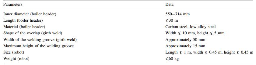
2 Working principle of the robot2.1 Functional requirementsThe body of a boiler header, as shown in Fig. 2a, is welded by seamless pipes, and the diameter generally ranges from 89 mm to 914 mm. The thickness ranges from 7 mm to 150 mm, and the length is approximately 23 m. The areas for improvement in the weld quality include the welding groove (see Fig. 2b) after two boiler headers are welded together in addition to the various joints and holes along the inner surface of the boiler header. These imperfections create a complicated working environment that needs to be taken into consideration in the design of the robot.

|
|
|
When the inner wall of the boiler header is polished, the robot is placed on the turning rolls horizontally, and the position of the robot is adjusted by the roller frame. The main functional requirements of the inner-wall robot are as follows.
(ⅰ) The robot must be able to work in pipes in diameter ranging from 550 mm to 714 mm. It must be able to move, locate, and avoid obstacles in the boiler headers.
(ⅱ) The robot will be equipped with a wire laser, a small light source, CCD cameras, and other sensors to enable it to locate the target overlap accurately.
(ⅲ) The robot must be able to implement local polishing in addition to whole-ring polishing of the boiler header.
(ⅳ) The operator must monitor the polishing area and evaluate the polishing quality by means of the CCD camera mounted on the robot.
In addition, other design criteria required for easy operation of the robot are assembled and summarized, as shown in Table 1.
The robot primarily comprises the moving structure and grinding structure. The moving structure moves the robot to the working position. The grinding structure is used to grind the weld bead along the inner walls of pipes. The image of the grinding operation is captured by the CCD camera and transmitted to a human-computer interface via a cable.
The working principle of the grinding structure is shown in Fig. 3. A pneumatic grinder is used as the grinding tool. For better contact between the grinding wheel and the inner wall of the boiler header, the grinding structure requires two degrees-of-freedom (DOFs) to adjust the position of the grinder. That is, the rotational DOF enables the grinder to rotate about the axis of the pipe while the second DOF is used for radial movement.

|
|
|
A force feedback control strategy was implemented in the radial adjustment module in order to achieve good grinding performance of the robot, as shown in Fig. 4. When the acting radial force between the grinding wheel and the weld bead differs from the desired force, the radial displacement of the grinding mechanism is adjusted to compensate for the force. Thus, the force feedback control strategy maintains a stable radial force while the grinding mechanism rotates.

|
|
|
A force sensor was installed at the junction of the grinding wheel and the grinding mechanism. Although the acting force between the grinding wheel and the weld bead is zero, the measured value of the force sensor changes when the grinding mechanism rotates because of the gravity of the grinding wheel. As shown in Fig. 5, F represents the acting force between the grinding wheel and the weld bead, Fs the measured force from the sensor, and G1 the radial component force of the gravity of the grinding wheel. Therefore, the acting force F can be calculated as
|
(1) |

|
|
|
The prototype of the polishing robot consists of three main structures: the motion structure, the positioning structure, and the polishing structure. An image of the polishing robot prototype is shown in Fig. 6. The prototype contains six functional units, including the polishing unit, the radial adjustment unit, the circumferential rotation unit, the cylinder jack-up unit, the robot body, and the motion unit. Furthermore, the robot has been equipped with two CCD cameras in order to be able to monitor the polishing area and polished surface.

|
|
|
Generally, an in-pipe robot can be categorized depending on its motion mechanism, such as wheel type [11–14], caterpillar type [15, 16], inchworm type [17, 18], walking type [19, 20], or screw type [21, 22]. According to the structural characteristics and the operation requirements of the boiler header, the wheel type was chosen for the robot in this study. Of the four wheels designed for the robot, the front two were driven by servo motors independently, and the two rear wheels were passive wheels. Furthermore, the left and the right wheels were arranged at a 90° relative to each other to achieve the movement and positioning of the robot in the pipelines.
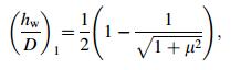
To ensure the robot's mobility, the diameter of its wheels needed to be larger than those of the holes it would encounter in the boiler header. Additionally, the robot needed to be able to move slowly when crossing obstacles. Accordingly, the obstacle-crossing capability of the robot in a static state was analyzed, as shown in Fig. 7. In Ref. [23], the maximum height of the front wheel that could move over obstacles was calculated as
|
(2) |

|
|
|
where D is the diameter of the front wheel and μ is the coefficient of sliding friction. For the front wheel, the maximum height of obstacle hw is irrelevant to the parameters of the robot.
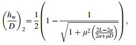
Moreover, the maximum height of the rear wheel that can pass the obstacle is calculated as [23]
|
(3) |
where L is the length between the front wheel and the rear wheel and a is the length from the font wheel to the center of gravity. For the rear wheel, the maximum height of obstacle hw is relevant to the parameters of the robot.
Based on the study of boiler headers in diameter ranging from 550 mm to 714 mm, it is known that the maximum diameter of the holes is 60 mm and the minimum distance between two holes is 180 mm in the axial direction of the boiler header. Therefore, for the wheel-type polishing inpipe robot, the diameter of the wheels was designed to be 125 mm and the length between the front wheel and the rear wheel was 320 mm.
Before the polishing operation, the robot uses the cylinder head and the clamp block to contact the inner-wall of the pipe. The clamping block and the wheels form a three-point support, which acts as a stable platform for the polishing operation.
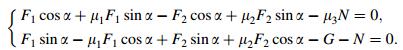
In order to analyze the robot's ability to withstand torsional moment in the process of polishing, a coordinate system was established based on the center of the boiler header as the origin. As shown in Fig. 8, F1, F2 are the supporting forces that the inner wall of the boiler header exerts on the left wheel and right wheel respectively. R is the radius of the boiler header, G the gravity of the robot, N the pressure that the inner wall of the boiler header acts on the cylinder roof, and α is the angle between the horizontal plane and the line connecting the contact point of the wheel and the center of the boiler header. μ1, μ2, and μ3 are the friction coefficients of the left wheel, right wheel, and clamp block, respectively, on the inner wall of the boiler header.

|
|
|
According to the static analysis, the following formulas can be obtained as
|
(4) |
Owing to the symmetrical arrangement of the boiler header wheel, F=F1=F2, it is
|
(5) |
Furthermore, the moment balance equation at the origin, O, is
|
(6) |
where M1 is the torque produced by the robot's grinding force. According to Eqs. (5) and (6), it could be calculated as
|
(7) |
According to the above formula, the robot's ability to withstand torsional moment would increase with pressure and frictional force, which the inner wall of the boiler header exerts on the cylinder lifting plate. Moreover, with an increasing radius of the boiler header, the angle α gradually decreases and the torsional moment gradually increases.
3.2 Positioning structureThe positioning at the welding overlap was achieved via interaction of the CCD camera and line lasers. The principle of the positioning is shown in Fig. 9, in which three line lasers and a CCD camera were used (line lasers a, b, c, and CCD d). Line laser a and laser b were located just below the polishing wheel, and emitted laser lines respectively from both sides of the polishing wheel to the pipe wall. Line laser c was located at the back side of the polishing wheel. However, its emitted laser line was opposite to the highest point of the polishing wheel. The CCD and the line laser c were disposed symmetrically. The CCD was used to capture information from the internal environment and the image of the polishing area.

|
|
|
The specific positioning method is described as follows: firstly, the robot enters the pipeline; then the lasers and the CCD camera become activated. A discontinuous signal of laser line c means that the weld bead has been found. The robot moves forward until the weld bead is in the middle of laser lines a and b. The robot stops at the desired position.
3.3 Grinding structureThe radial adjustment module was divided into two parts: the manual adjustment component and the automatic adjustment component. Firstly, the rotation center of the circumferential rotation component was aligned with the central axis of the boiler header through manual adjustment of the screw mechanism. Then, the radial position of the polishing wheel was adjusted by the servo motor to drive the ball screw mechanism. The polishing wheel rotated to face the polishing area via the circumferential rotation unit. The force sensor in the radial adjustment unit was used to detect the polishing pressure of the polishing wheel. The robot adjusted the radial position of the polishing wheel according to the polishing pressure of the force sensor, so the polishing could be conducted within a certain pressure range.
4 Control system4.1 Control systemThe control system consists of a human interface, a control cabinet, and the robot body, as shown in Fig. 10. The communication between all control units and IPC was performed by a CAN bus, and CANopen was employed as the communication protocol. Four DC servomotors were used to control the robot's movement and position of the grinding mechanism. For the IPC, there were five digital inputs for collecting the signals of the proximity sensors, one analog input for collecting the signal of the force sensor, and two digital outputs for controlling two solenoid valves. The robot's air cylinder of the supporting mechanism and the grinding wheel were driven by the air pressure. Furthermore, the control handle was used as the interactive input. Two CCD cameras communicating with the IPC via Ethernet were used as the video monitoring system. Another one was added to the front of the robot's body for observing the environment of the forward motion. The last one was added to the grinding module for observing the grinding area. The power module could supply DC 24 V for driving all functional modules. Moreover, the control system software adopted VS2010 as the application development infrastructure. WPF was used as the application framework and C# was used as the programming language.

|
|
|
According to the settings, the robot followed an orderly working process, as shown in Fig. 11.

|
|
|
With the assistance of a CCD camera, two laser lines emitted from the line lasers were located by the robot on the two sides of the weld bead. A sensor was installed at the top of the cylinder head and used to determine whether the lifting block was raised or not. In the process of grinding, the position of the grinding wheel was adjusted by the signal of the force sensor.
5 Experiments5.1 Manual grinding experimentIn order to investigate the effects of the grinding force vibrations, a UR5 industrial robot with a pneumatic grinder was used to carry out the grinding experiment, as shown in Fig. 12. The experimental acting force and the speed of the movement were obtained by simulating manual grinding. The optimized acting force was approximately 50 N and the moving speed was 29 mm/s. The manual grinding experiment provided a reference for adjusting the robot's grinding force.

|
|
|
In order to confirm the effectiveness of the gravity compensation strategy, a rotary motion experiment of the grinding mechanism was conducted when the acting force F between the grinding wheel and the weld bead was zero. As depicted in Fig. 13, the results show that the feedback acting force is approximately equal to zero during the experiment when the gravity compensation is utilized.

|
|
|
The experimental platform of the robot prototype was constructed as part of this study. The boiler header was comprised of a common steel pipe having an inner diameter of 660 mm, the outer diameter of 830 mm and an axial length of 6 m. Figure 14 shows the experimental process: (a) the robot was hoisted into the boiler header; (b) the moving performances of the robot, such as acceleration, deceleration, stop, forward and backward, were tested by sending the instructions to the robot's motion module; (c) the robot performed grinding on the weld bead in the boiler header; (d) the condition of the grinding operation was monitored by an operator via CCD camera; (e) a surface polished by manual grinding; (f) a surface polished by robot grinding.

|
|
|
The experimental results show that the robot could achieve all kinds of movement accurately and timely according to the control instructions. Moreover, the grinding surface by robot grinding was smoother than that by manual grinding. Thus, the quality of robot grinding is higher and more reliable.
6 ConclusionsA simple and novel wheel-type in-pipe polishing robot was designed and prototyped in this study. The working principle as well as the structure and control system are presented herein. Experiments were conducted, confirming the ability of the robot to move, locate, and polish accurately and quickly with high quality. The robot is capable of meeting application requirements effectively, and has the advantageous characteristics of compact structure, strong adaptability, good driving performance, and high grinding efficiency. Future works will include further study of automation and reliability of the polishing robot.
| 1. | Yang HJ (1996) Safety monitoring of boiler pressure vessel in power station. China Water & Power Press, Beijing, pp 96-126 |
| 2. | Zhang HM, Yang XC(2012)Interface between LabVIEW and FANUC robot. Adv Mater Res 443, 464-470 |
| 3. | Rafieian F, Girardin F, Liu Z, et al(2014)Angular analysis of the cyclic impacting oscillations in a robotic grinding process.Mech Syst Signal Process 44, 160-176 doi:10.1016/j.ymssp.2013.05.005 |
| 4. | Chen Q, Sun Z, Zhang W et al (2008) A robot for welding repair of hydraulic turbine blade. In: IEEE conference on robotics, automation and mechatronics, Chengdu, China. pp 155-159 |
| 5. | KASRO working robot. http: //prokasro. de/en/products/workingrobots-pneumatic. Accessed 20 Apr. 2016 |
| 6. | Mirats JosepM, Tur WilliamGarthwaite(2010)Robotic devices for water main in-pipe inspection: a survey.J Field Robot 27(4), 491-508 doi:10.1002/rob.v27:4 |
| 7. | Luis AM, Markus V (2011) Developing water loss prevention-DeWaLoP in-pipe robot system. In: 20th international workshop on robotics in alpe-adria-danube region, Bron, Czech Republic, pp 1-9 |
| 8. | Mateos LA, Zhou K, Vincze M (2012) Towards efficient pipe maintenance: DeWaLoP in-pipe robot stability controller. In: international conference on mechatronics and automation, Chengdu, China, pp 1-6 |
| 9. | Mateos LA, Vincze M (2013) LaMMos-Latching mechanism based on motorized-screw for reconfigurable robots. In: international conference on advanced robotics, Montevideo, Uruguay, pp 1-8 |
| 10. | Mateos LA, Vincze M(2012)DeWaLoP in-pipe robot position from visual patterns. Mex Int Conf Adv Artif. 7629, 239-248 |
| 11. | Qiao JW, Shang JZ(2013)Application of axiomatic design method in in-pipe robot design.Robot Comput Integr Manuf 29(4), 49-57 doi:10.1016/j.rcim.2012.10.007 |
| 12. | Park JJ, Moon JW, Kim H et al (2013) Development of the untethered in-pipe inspection robot for natural gas pipelines. In: international conference on ubiquitous robots and ambient intelligence, Jeju, Korea, pp 55-58 |
| 13. | Min J, Setiawan YD, Pratama PS et al (2014) Development and controller design of wheeled-type pipe inspection robot. In: international conference on advances in computing, communications and informatics. Delhi, India, pp 789-795 |
| 14. | Ye C, Liu L, Xu X et al (2015) Development of an in-pipe robot with two steerable driving wheels. In: international conference on mechatronics and automation, Beijing, China, pp 1955-1959 |
| 15. | Kakogawa A, Ma S, Hirose S (2014) An in-pipe robot with underactuated parallelogram crawler modules. In: IEEE international conference on robotics and automation, Hong Kong, China, pp 1687-1692 |
| 16. | Sahari KSM, Anuar A, Mohideen SSK et al (2012) Development of robotic boiler header inspection device. In: joint international conference on soft computing and intelligent systems, Kobe, Japan, pp 769-773 |
| 17. | Qiao J, Shang J, Goldenberg A(2013)Development of inchworm in-pipe robot based on self-locking mechanism.IEEE/ASME Trans Mechatron 18(2), 799-806 doi:10.1109/TMECH.2012.2184294 |
| 18. | Tanaka T, Harigaya K, Nakamura T (2014) Development of a peristaltic crawling robot for long-distance inspection of sewer pipes. In: IEEE international conference on advanced intelligent mechatronics, Besancon, France, pp 1552-1557 |
| 19. | Yu X, Chen Y, Chen M et al (2015) Development of a novel inpipe walking robot. In: IEEE international conference on information and automation, Lijiang, China, pp 364-368 |
| 20. | Galvez JA, Santos PGD, Pfeiffer F(2001)Intrinsic tactile sensing for the optimization of force distribution in a pipe crawling robot.IEEE/ASME Trans Mechatron 6(1), 26-35 doi:10.1109/3516.914388 |
| 21. | Nayak A, Pradhan SK(2014)Design of a new in-pipe inspection robot.Proced Eng 97, 2081-2091 doi:10.1016/j.proeng.2014.12.451 |
| 22. | Li T, Ma S, Li B et al (2015) Design and locomotion control strategy for a steerable in-pipe robot. In: IEEE international conference on mechatronics and automation, Beijing, China, pp 1228-1233 |
| 23. | Yin QH, Kong FR(2012)Crossing ability analysis of triaxial differential pipeline robot. J Mech Electr Eng 29(12), 1371-1375 |