 2017, Vol. 5
The article information
- Wang Hua,Ye Jian-Min,Liang Hang-Feng,Miao Zhong-Hua
- A medical image encryption algorithm based on synchronization of time-delay chaotic system
- Advances in Manufacturing, 2017, 5(2): 158-164.
- http://dx.doi.org/10.1007/s40436-017-0178-5
-
Article history
- Received: 9 October, 2016
- Accepted: 25 April, 2017
- Published online: 1 June, 2017


With the rapidly developing electronic technology, hospitals are adopting an increasing number of electronic equipment, including the picture archiving and communication systems (PACS) [1]. In such systems, the diagnosis results of patients are stored in the form of digital images. These images contain the patients' personal information. Random access to these images may cause serious social problems [2]. Consequently, storing and safely transferring patient data are presently becoming hot topics.
Using cryptography technology to protect digital information is an effective method. In the 1970s, conventional encryption algorithms, such as data encryption standard (DES), advanced encryption standard (AES) and international data encryption algorithm (IDEA) [3] processed information as a binary stream. A digital image has its own characteristics, such as high correlation in adjacent pixels, data redundancy, uneven distribution of energy, etc. [4]. Hence, the conventional encryption algorithm cannot be successfully applied to a digital image.
In recent years, increasing attention has been focused on the research of an image encryption technique based on chaos synchronization [5]. Many methods were adopted to realize chaos control and synchronization. These included the control Lyapunov function [6], nonlinear control [7], adaptive control [8], back stepping control [9], passive control [10], and sliding-mode control [11] methods, etc. In a real physical process, some time-delays are trivial, such that they can be ignored. However, others cannot be disregarded, particularly in long-distance communication and with transmission congestion. Therefore, studying the synchronization in such systems with delays is important and necessary [12–15].
In this study, we mainly focused on the medical image encryption technology based on chaos synchronization. Firstly, we deal with the problem of designing a linear controller to realize the chaotic synchronization for the time-delay chaotic system. Subsequently, we apply the newly developed method in the research of medical image encryption. Thirdly, some simulation works are presented to illustrate the feasibility of the proposed algorithm.
2 Time-delay chaotic system synchronizationSome necessary lemmas are introduced herein before the main results are presented.
Suppose C=C([-r, 0], Rn) is the Banach space of continuous functions mapping the interval [-r, 0] into Rn with the topology of uniform convergence. Let xt ∈ C be defined by xt(θ) = x(t+θ), -r≤θ ≤ 0.
The following autonomous equation must be considered as

|
(1) |
where f : C→Rn is a completely continuous function, and the solutions of Eq. (1) continuously depend on the initial data.
Lemma 1 [16] Let V(t, xt) be a differentiable scalar functional for all t ≥ 0 and xt ∈ C. M is a positive number. If there is a bounded continuous function Φ1[0, ∞) → [0, ∞), which is L1[0, ∞) with 
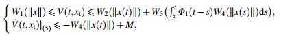
|
(2) |
where Wi (i = 1, 2, 3, 4) is a wedge, and the solutions of Eq. (1) are uniformly bounded.
Lemma 2 [17] We are particularly interested in the globally asymptotically stable (GAS) problem of the cascade delay system in the following form

|
(3) |
where 

If
(ⅰ) the equilibrium η = 0 of system 
(ⅱ) the equilibrium Ψ = 0 of 
(ⅲ) the solution of the whole system (Eq. (3)) is bounded.
The equilibrium Ψ=0, η=0 of the whole system (Eq. (3)) is GAS.
Lemma 3 [18] Let a1 and b1 be the two n-dimensional vectors, and 

|
(4) |
This study aims to design a linear controller for the chaotic secure communication system with state delay to realize the synchronization between the transmission and the reception ends. Therefore, the original message can be recovered at the reception end.
Consider the following time-delay chaotic system as the transmitter system
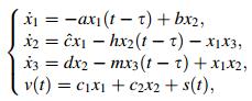
|
(5) |
where x1, x2, and x3 are state variables; a, b, 


|
|
|
The receiver system is presented as
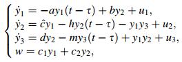
|
(6) |
where w is the output of the receiver system, and u1, u2 and u3 are the controllers to be designed. We assume here that all the states y1, y2 and y3 are available for the feedback controller. The synchronization errors are denoted as ei = yi -xi(i = 1, 2, 3). Subtracting Eq. (6) from Eq. (4) yields the following error system

|
(7) |
The slave system (Eq. (6)) can successfully synchronize the drive system (Eq. (5)) if the synchronization error system (Eq. (7)) is stable. We will adopt three steps in the following to design the linear controllers that attain this goal.
Step 1 Design u1 = -be2 -k1e1, where the controller parameter k1 can be determined later by the solution of a linear matrix inequality (LMI). The first equation of the error system (Eq. (7)) will be presented as follows when the controller is applied

|
(8) |
In the following, we will prove that the error system (Eq. (8)) is asymptotically stable and bounded. The following candidate of the Lyapunov-Krasovskii function is considered as

|
(9) |
Its derivation along the solution of the system (Eq. (8)) is then calculated, and we obtain
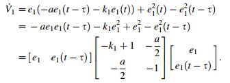
|
(10) |
We know from the Lyapunov-Krasovskii stability theory that the error system (Eq. (8)) will be asymptotically stable and bounded if a scalar k1 exists, such that the following LMI is solvable

|
(11) |
In other words, a constant ρ1 exists, such as |e1| ≤ ρ1.
Step 2 Consider the second and third equations of the error system (Eq. (7))

|
(12) |
The system (Eq. (12)) can be simplified as follows when e1 = 0

|
(13) |
The linear controllers should then be designed as u2 = -k2e2(t), u3 = -k3e3(t), where the controller gains k2, k3 are to be later determined by the solution of an LMI.
Consider the following candidate of the LyapunovKrasovskii function
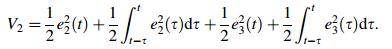
|
(14) |
Its derivation along the solution of the error system (Eq. (13)) is calculated to obtain
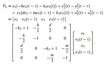
|
(15) |
We know from the Lyapunov-Krasovskii stability theory that the simplified error system (Eq. (13)) is asymptotically stable if two real numbers (i.e., k2 and k3) exist, such that the following LMI is solvable

|
(16) |
We can see that the error system (Eq. (13)) is greatly simplified than Eq. (12) because we can consider e1 as zero. Any item coupled with e1 can be treated as zero, which is one advantage of the proposed method.
Step 3 In this step, we will prove that the solution of the whole error system (Eq. (7)) is bounded. Step 1 showed that the error state e1 was bounded by a positive constant ρ1. Hence, we only need to prove that the error states e2 and e3 are bounded under the suppression of the linear controller u2, u3. Consider the following candidate positive function

|
(17) |
Its derivation along the error system (Eq. (7)) is calculated to obtain

|
(18) |
We know from Step 1 that |e1| is bounded by |e1| ≤ ρ1. The transmitter system (Eq. (6)) is a chaotic system; hence its states are bounded. Some positive constants, such |xi| ≤ ki, are then found to exist. We can obtain the following equation from Lemma 3

|
(19) |
where ηi(i = 1, 2, 3) are arbitrary positive constants.
Subsequently, we can obtain the following inequality

|
(20) |
Denote

|
(21) |
We can see that M is a positive constant. We can conclude from Lemma 1 that the solutions of the error system (Eq. (7)) will be bounded if some positive real numbers ηi(i = 1, 2, 3) and general real numbers ki(i = 2, 3), such that the LMI Φ < 0, exist. Combining the proof process of Steps 1-3, we know from Lemma 2 that the time-delay chaotic error system (Eq. (7)) can be stabilized by the linear controller ui(i = 1, 2, 3).
3 Simulation of the chaos synchronization systemThe simulation work herein was processed in MATLAB R2010a. A DDE23 solver was used to solve the delay differential equations. The parameter values are as follows: 

|
|
|
Figure 2 shows that the trajectories of the receiver systems can asymptotically approach the trajectory of the transmitter chaotic systems, while Fig. 3 illustrates that the error states asymptotically approach zero. The controller proposed was linear and easy to be applied in a real physical process.

|
|
|
In the process of secure communication, the signal "s" to be transmitted is first embedded in the chaotic signals. The synthesized signal will then be transmitted through a common channel. A slave chaotic system is used at the receiver terminal. The controller in the receiver terminal can drive the system to synchronize with the transmitter system, and the original signal "s" can be decrypted. Figure 4 shows a diagram of the whole process.

|
|
|
In this section, a medical skull image P measuring M × N was used for encryption. x1(0), x2(0) and x3(0) were the initial values of the transmitter system. Although the transmitter (Eq. (5)) and receiver (Eq. (6)) systems were continuous systems, the simulation work was conducted using a computer, and discrete sequences were produced. Hence, we can directly utilize the sequence produced by MATLAB to do the encryption work. An encryption method was proposed in Ref. [19], shown as follows.
Step 1 Transform the plain matrix P0 to a vector 
Step 2 Divide the obtained vector 

|
(22) |
where N1 is determined by the user and 
Step 3 Generate a chaotic sequence (xjk), j = 1, 2, ..., Nk, k = 1, 2 of length Nk. The sequence is generated by iterating the chaos system given by Eq. (5).
Step 4 Quantize the (xjk), j = 1, 2, ..., Nk coefficients by applying Eq. (23). Here, denote the obtained key stream as

|
(23) |
Step 5 Sort the chaotic sequences according to the ascending order to get the address sequence code 
After verification, we found that the method of Ref. [19] was effective for the general image. The medical image mainly contained the black and white colors. Hence, dividing it into different blocks was hard. This method was not suitable for the medical image, and realizing the encryption took much time. Figure 5 shows the encryption result.

|
|
|
We aim to improve and optimize this method in combination with the inherent characteristics of a medical image.
Step 6 Generate the cipher blocks (cj), j = 1, 2, ..., Nk by applying

|
(24) |
Step 7 Concatenate. Firstly, let's construct a vector c of length MN from the blocks (cj), j = 1, 2, ..., Nk. Also, we can denote this vector as c(MN). Then two chaotic sequences (xjk), j = 1, 2, ..., Nk; k= 1, 2 of length M × N can be generated by iterating the chaotic system (Eq. (5)).
Step 8 Embed the signal s in the output of the drive system by v = c1x1 + c2x2 + s. Here, v is a vecotor containing M × N elements and we can denote it as v(MN). Then the original image can be encrypted by reshaping the vector v to a matrix V0 of size M × N.
The whole encryption process can be described in Fig. 6.

|
|
|
The image was encrypted after the abovementioned steps have been performed. The image signal can by recovered if the receiver system synchronizes the transmitter system. The decryption process is the inverse process of the encryption process, and it is omitted here.
4.3 Encryption and decryption simulation experimentA medical skull image measuring 128 × 128 was adopted in this section as the signal to be encrypted (see Fig. 7). The encryption key was generated by the transmitter chaotic system. Figure 8 shows the obtained encryption image.

|
|
|

|
|
|
The slave chaotic system (Eq. (6)) was used to generate the decryption key. The decrypted image can be obtained after the above decryption process (see Fig. 9).

|
|
|
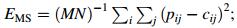
The peak value signal-to-noise ratio (PSNR) is usually used to evaluate the visual impression of the cipher image. The cipher image was equal to add noise to the plain image. The encryption effect defined as follows will then be better when the PSNR value (RPSN) is lower:

|
(25) |
where Ψmax is the maximum of the pixel color component;

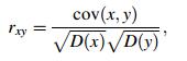
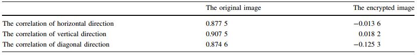
The standard test medical image of size 128 × 128 was selected herein to test the property of the resisting statistical analysis. We randomly selected 1 000 pairs of two adjacent pixels, including vertically, horizontally, and diagonally adjacent pixels, to calculate the correlation of the two adjacent pixels. We then calculated the correlation coefficient of each pair using the two following formulas [20]

|
(26) |
|
(27) |
where x and y are the gray-scale values of the two adjacent pixels in the image. The following discrete formulas are employed in the numerical computation

|
(28) |
|
(29) |
|
(30) |
Table 2 shows the results of the horizontal, vertical, and diagonal directions. The correlation coefficients of the cipher images were very small, which implied that no detectable correlation existed between the original and its corresponding cipher images. Therefore, the proposed algorithm had high security against statistical attacks.
This paper proposed a novel linear feedback controller to achieve synchronization and secure communication in time-delay chaotic systems. A secure message can be successfully recovered. The key has a long enough period and can be used for medical image encryption. Compared with the general image, the medical image has large pieces of black and white areas. This characteristic enables the traditional encryption to have no obvious effect. The proposed algorithm made up for the shortcomings, and the numerical simulations were provided to show the effectiveness of our methods.
Acknowledgements This project supported by the National Natural Science Foundation of China (Grant Nos. 51375293, 31570998), and the Science and Technology Commission of Shanghai Municipality (Grant No. 16511108600).| 1. | Zhu Z, Zhang W, Wong K, et al(2011)A chaos-based symmetric image encryption scheme using a bit-level permutation.Inf Sci 181(6), 1171-1186 doi:10.1016/j.ins.2010.11.009 |
| 2. | Wang Y, Wong KW, Liao X, et al(2011)A new chaos-based fast image encryption algorithm.Appl Soft Comput 11(1), 514-522 doi:10.1016/j.asoc.2009.12.011 |
| 3. | Patil P, Narayankar P, Narayan DG, et al(2016)A comprehensive evaluation of cryptographic algorithms: DES, 3DES, AES, RSA and blowfish.Proc Comput Sci 78, 617-624 doi:10.1016/j.procs.2016.02.108 |
| 4. | Lei ZK, Sun QY, Ning XX(2010)Image scrambling algorithms based on knight-tour transform and its applications.J Chin Comput Syst 31(5), 984-989 |
| 5. | Chen GR, Dong XN(1998)From chaos to order: methodologies, perspectives and applications.Methodol Perspect Appl World Sci Singap 31(2), 113-122 |
| 6. | Wang H, Han ZZ, Zhang W, et al(2009)Synchronization of unified chaotic systems with uncertain parameters based on the CLF.Nonlinear Anal Real World Appl 10(2), 715-722 doi:10.1016/j.nonrwa.2007.10.025 |
| 7. | Chen MY, Han ZZ(2003)Controlling and synchronizing chaotic genesio system via nonlinear feedback control.Chaos Solitons Fractals 17(4), 709-716 doi:10.1016/S0960-0779(02)00487-3 |
| 8. | Yassen MT(2006)Adaptive chaos control and synchronization for uncertain new chaotic dynamical system. Phys Lett A 350(1), 36-43 |
| 9. | Li GH(2006)Projective synchronization of chaotic system using back stepping control.Chaos Solitons Fractals 29(2), 490-494 doi:10.1016/j.chaos.2005.08.029 |
| 10. | Wang FQ, Liu CX(2007)Synchronization of unified chaotic system based on passive control.Phys D Nonlinear Phenom 225(1), 55-60 doi:10.1016/j.physd.2006.09.038 |
| 11. | Tavazoei MS, Haeri M(2007)Determination of active sliding mode controller parameters in synchronizing different chaotic systems.Chaos Solitions Fractals 32(2), 583-591 doi:10.1016/j.chaos.2005.10.103 |
| 12. | Mei J, Jiang MH, Wang B, et al(2013)Finite-time parameter identification and adaptive synchronization between two chaotic neural networks.J Franklin Instit 350(6), 1617-1633 doi:10.1016/j.jfranklin.2013.04.005 |
| 13. | Aghababa MP, Khanmohammadi S, Alizadeh G(2011)Finitetime synchronization of two different chaotic systems with unknown parameters via sliding mode technique.Appl Math Model 35(6), 3080-3091 doi:10.1016/j.apm.2010.12.020 |
| 14. | Wang H, Zhang XL, Wang XH, et al(2012)Finite time chaos control for a class of chaotic systems with input nonlinearities via TSM scheme.Nonlinear Dyn 69(4), 1941-1947 doi:10.1007/s11071-012-0398-y |
| 15. | Jiang GP, Zheng WX, Chen GR(2004)Global chaos synchronization with channel time-delay.Chaos Solitons Fractals 20(2), 267-275 doi:10.1016/S0960-0779(03)00374-6 |
| 16. | Burton T (1985) Stability and periodic solutions of ordinary and functional differential equations. Academic Press, London |
| 17. | Wang H, Wu JP, Sheng XS, et al(2015)A new stability result for nonlinear cascade time-delay system and its application in chaos control.Nonlinear Dyn 80(1-2), 221-226 doi:10.1007/s11071-014-1862-7 |
| 18. | Cao Y, Sun Y, Cheng C(1998)Delay-dependent robust stabilization of uncertain systems with multiple state delays.IEEE Trans Automat Contr 43, 1608-1612 doi:10.1109/9.728880 |
| 19. | Mannai O, Bechikh R, Hermassi H, et al(2015)A new image encryption scheme based on a simple first-order time-delay system with appropriate nonlinearity.Nonlinear Dyn 82(1-2), 107-117 doi:10.1007/s11071-015-2142-x |
| 20. | Zhu CX, Huang DZ, Guo Y(2010)A image encryption algorithm with multi chaotic maps and output feedback.Geomat Inf Sci Wuhan Univ 35(5), 528-531 |