 2017, Vol. 5
The article information
- H.C. Fang,S.K. Ong,A.Y. C. Nee
- Adaptive pass planning and optimization for robotic welding of complex joints
- Advances in Manufacturing, 2017, 5(2): 93-104.
- http://dx.doi.org/10.1007/s40436-017-0181-x
-
Article history
- Received: 28 February, 2017
- Accepted: 2 May, 2017
- Published online: 1 June, 2017


Driven by the lack of skilled welders as well as the requirement on welding quality and efficiency, robotic work cells have been the solution for the general welding industry [1]. Today's industrial welding robot systems, however, cannot replace skilled human workers in welding complex joint structures, e.g., cross-tubular structure of jack-up rigs in shipyards or offshore industries, due to the need for long setup time and tedious teaching procedures. The major challenges on planning welding tasks for such complex work-pieces are, namely, the presence of all-position welding positions that requires special welding process skills, and the non-uniform and irregular geometries of the welding groove. Addressing the first challenge would need the development of an adaptive welding knowledge base from which suitable welding parameters can be drawn for different welding positions. The second challenge would require suitable task planning methods to address unexpected changes in the welding groove model. Therefore, such a welding task should be planned at both the welding pass and robot path levels, with suitable welding parameters determined based on best welding practices.
Many types of robot welding systems have been developed to address the all-position welding, for instance, the use of auxiliary base track or gantry system to increase the reach of a robot, adoption of turntable or positioner to translate all the welding positions into horizontal or flat position, etc. [2]. For robot programming methods, offline programming with graphical user interfaces remains dominant in today's industrial welding robot systems [3, 4], providing a CAD-based environment in which the welding task can be planned, modified and simulated prior to task execution. Augmented reality-based robot programming methods [5–7] improved offline programming by enabling adequate human intervention during task planning; this approach is more suitable for generating collision-free paths for un-structured/ad-hoc working environments, e.g., a shipyard.
In multiple welding pass planning, the relationships between the welding bead shape and the welding parameters have been extensively studied. Thus far, there is no universal formulation of the welding bead model that is suitable for most welding scenarios. Welding bead geometry has been approximated into different shapes, e.g., parallelograms or trapezoids [8], sine functions and parabola function [9–11], etc. Experimental methods, e.g., regression analysis [12, 13] and artificial neural networks (ANNs) [14, 15] have been reported to have superior performance in predicting welding bead shape based on welding parameters, i.e., wire feed rate, wire diameter, welding speed, welding current, arc voltage, etc., as compared to induced equations [8, 11], in which the amount of weld material deposited is proportional or equal to the amount of wire melted. Nevertheless, the performance of experimental methods is highly dependent on the validity of the experimental data used for training the welding bead model. In addition, most of the reported studies focused on pass planning for welding thick plates without considering variations in the groove geometry. Yan et al. [16] developed a multi-pass planning algorithm to minimize the number of passes required to fill the deep groove with uniform cross section based on the available welding parameters.
Performing an arc welding task with general industrial welding robots always presents a task redundancy, which is the rotation of the torch around its symmetry axis that has no effect on the inclination angle of the torch. Huo and Baron [17, 18] addressed this issue by developing a twist decomposition algorithm to generate feasible robot paths considering robot joint limits and singularity avoidance. Ogbemhe and Mpofu [19] reviewed general robot trajectory planning and trajectory tracking methods that could be applied in robotic arc welding task planning. This paper adopted a beam search algorithm based method for robot path planning optimization [20], using which the robot motion for a given welding pass was optimized considering both the welding task requirement and the kinematic capabilities of the robot, i.e., the robot joint movement along a welding pass had to be minimized subject to the robot reachability, singularity avoidance, and robot motion consistency.
An adaptive approach is proposed in this paper, in which a welding task with irregular welding groove geometry is planned at both the welding pass and robot path levels. Welding pass planning involves the determination of the number of segments, layers, and passes to fill the groove. The size of the welding bead is tuned by adjusting the relevant welding parameters to fit the cross section of the groove. With proper welding torch orientation and welding speed, the associated robot paths are generated to achieve minimum accumulative joint motion. The pass planning result based on the proposed approach is simulated in the planning of the welding task of a full-size Y-type joint.
2 Overview of the adaptive approach for robotic welding of complex jointsFigure 1 outlines the proposed architecture for adaptive robot planning and optimization for welding complex joints. It contains two main modules including welding pass planning and adaptation, robot path planning and optimization. One objective of the pass planning module is to generate a set of welding passes subject to consistent welding parameters, taking the welding groove model and the welding bead model as the inputs. The second objective of the module is to adjust or modify the welding passes for the compensation of possible discrepancies between the actual thickness of the cumulative welding seams and that of the planned results. The planned pass data will be used as input to the robot path planning module. For each welding pass, the selection of the welding travel angle and work angle are in accordance with the welding position based on welding expertise. The corresponding robot path to achieve minimum joint motion is generated subject to two constraints, viz., reachability and singularity avoidance.

|
|
|
Figure 2a depicts a CAD model of a scaled-down Y-joint structure, which consists of a main pipe and a branch pipe with a 45° intersection angle between the two pipes. Figure 2b shows the welding groove model reconstructed from the scanning data of a Y-joint obtained using a 3D profile scanning device. The groove model is represented by a sequence of cross-sections, with the curve (in red color) defining the centroid of the groove.

|
|
|
The boundary of a cross section is given by a set of sequentially parameterized points (blue dotted curve in Fig. 3). In this research, the cross section is represented by four spatial points (P1–P4). The first three points (P1–P3) are located using a threshold technique by computing and filtering the tangent vector at each point. The point P4 lies on the outer surface of the main pipe and is located based on the requirement on the welding thickness for different joints included angle [19]. Figure 3 defines the local coordinate frame associated with each cross section. The mid-point of P2–P3 denotes the origin of the coordinate frame (O); the direction of P3–P2 defines the x-axis; the y-axis is within the plane of cross section perpendicular to x-axis; The normal of the cross section denotes to the z-axis, which can also be used to define the welding direction. Noting that there could be two alternative welding directions while keeping y-axis the same, the alternative x-axis and z-axis should be chosen with an opposite direction.

|
|
|
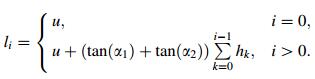
As shown in Fig. 3, the groove base width at a particular cross section is denoted by u, and the height of the cross section or the groove depth, is denoted by H. Pm is the intersecting point between the bi-sector of the cross section and the segment P1–P4, and H is determined by projecting point Pm to the y-axis. α1 and α2 are the two angles defined between the two sides of the cross section and the y-axis, which will be used for pass layout planning. hi and li denote the height and width of the ith layer, and wi, j denotes the base width of jth pass at the ith layer. As illustrated in Fig. 3, the base width for the ith layer can be calculated using Eq. (1).
|
(1) |
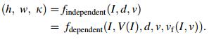
In this research, three types of independent welding parameters are considered, namely, welding current (I), welding speed (v), and contact-tube workpiece distance (CTWD). Another two correlated parameters are arc voltage (V) associated with welding current, and feed rate (vf) associated with both welding current and welding speed. These parameters are taken as variables for welding bead geometry modelling, i.e., to determine both the height (h) and the width (w) of the weld bead generated with respect to the different welding positions (κ). As given in Eq. (2), in which findependent gives the function considering the independent welding parameters only, while the function findependent takes into account both the independent and the dependent variables. The associated coefficients for the two functions can be determined using the linear regression approach given a sufficient set of welding parameters data.
|
(2) |
Common practices in manual arc welding suggest that in arc welding, it is best to keep the welding parameters unchanged in order to produce a stable and consistent weld pass. In this research, however, the welding parameters will need to be adjusted along a welding pass to cater for the changes in groove geometry. Here, it is assumed that changing welding current and CTWD may have a more significant effect on welding quality deterioration. Therefore, these two parameters remain unchanged, with both welding speed and weave size modifiable within their respective range. The effect of welding speed on the weld bead dimension would be that the higher the welding speed, the lower the bead height, and the narrower the bead width.
2.3 Multi-pass representationIn multi-layer and multi-pass welding, a number of distinct parameters need to be determined to represent a specific welding pass for multi-pass data management. The parameters can be categorized into three types, namely, welding pass index, parameters relevant to the welding process, and subsequent robot path generation, as shown in Table 1.
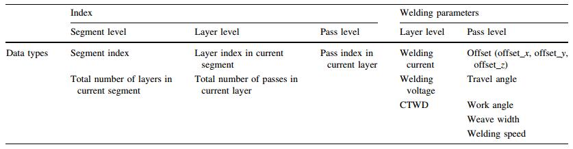
The output for pass planning includes the segment index, the number of layers planned to fill-up this segment, the number of passes at each layers, and the welding parameters associated with each layer and pass. The index is managed in three levels, i.e., segment level, layer level and pass level. At each layer, the same set of welding parameters, such as welding current and arc voltage, CTWD, is used. At each pass, the welding parameters, e.g., the position offset, travel angle, work angle, welding speed and weave width are stored as planned for each groove section. Noting that the position offset can be given with respect to either the centroid pass, or the robot origin coordinate frame.
2.4 Assumptions and general planning strategyWelding bead modeling has been a highly complex and computational task. Considering the effect of the bead shape modeling on the welding pass planning, a few assumptions based on common welding practices are made as follows:
(ⅰ) The fewer number of welding segments, the better is the welding quality as the overlapped area often has poor welding quality.
(ⅱ) Up-hill welding direction is preferred for all welding positions.
(ⅲ) The number of layers for all the cross sections of a segment remains unchanged. In addition, the number of passes to fill-up any layer remains the same. This is to reduce the number of start and end welding areas within the segment.
(ⅳ) For each welding pass, the welding current (and arc voltage) and the CTWD are maintained unchanged during the planning stage, aiming at reducing possible welding defects due to the variations in these parameters during welding process.
(ⅴ) The weld bead geometry (i.e., width and height) along the pass can be adjusted through changing the welding speed, or introducing weave to compensate for the geometry variation in the cross section. It is also assumed that the weave will have no effect on welding speed.
(ⅵ) To achieve a flat layer surface, the weld bead shape is modelled using a parallelogram for the first few passes, and a trapezium for the last pass, as illustrated in Fig. 3. It can also be modelled using a parabolic curve [16], in which the overlapped area between adjacent passes should be equal to the valley area between the passes.
3 Welding pass planning and adaptationThe proposed pass planning and adaptation methodology can be further divided into three sequential modules, viz., (ⅰ) welding groove representation and segmentation, (ⅱ) welding pass planning and optimization to fill-up each segment, and (ⅲ) pass planning results adaptation or replanning at any welding intervals, where there could be updated groove scanning data available after a few layers of welding. These three modules will be presented in details respectively in the following sections.
3.1 Welding groove segmentationIn the welding of a cross-tubular structure, the welding groove is typically divided into a few segments to reduce the distortion caused by uneven welding heat distribution. The number of segments should be adequate as too many segments would result in excessively overlapped welding zones, and a higher possibility of lower welding quality. Secondly, it is possible that no continuous robot motion exists to cover the entire groove without encountering a singular configuration. Thirdly, the presence of non-uniform groove geometry would require the groove to be divided into multiple segments to facilitate pass planning in achieving more consistent welding pass solution.
The initial criteria for identifying welding segments can be the reachability of the welding robot being used, or based on the welding position, groove angle, etc. If an uphill welding direction is only allowed, at least two segments are needed. Typical numbers of segments are 2, 4 or 6, as illustrated in Fig. 4a. Figure 4b describes a groove segmentation scheme based on different welding positions, e.g., horizontal position (segment 1), overhead position (segment 2), and vertical position (segments 3 and 4).

|
|
|
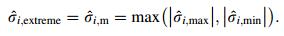
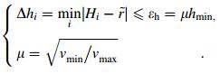
Another welding groove segmentation scheme can be based on the variations in groove geometry. Each of the resulting segment aims to yield a relatively less variation in both groove depth and width, viz., within an allowable range, such that a set of consistent welding parameters can be determined for all the passes and layers planned to fillup the segment. This variation range is governed by the maximum changes permitted in the two adjustable welding parameters, namely, welding speed and weave. Figure 5 describes the detailed procedure for groove segmentation based on this criterion.

|
|
|
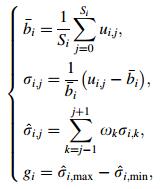
All the cross sections of a groove are first grouped into segments based on an initial segmentation scheme (e.g., welding positions (as illustrated in Fig. 4b). The number of segments is denoted by Nt. Secondly, for each segment, the average groove base width is calculated; the variation on each cross section is calculated and smoothened by weighted averaging of variations of the neighboring cross sections, using Eq. (3). In Eq. (3), 

|
(3) |
where 

|
(4) |
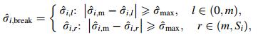
This cross section determined using Eq. (4) serves as the starting point for searching possible break points (

|
(5) |
where 
|
(6) |
If no break point is identified, the boundary of the segment remains unchanged, and it proceeds to the next segment. If one or two break points have been identified, the break point(s) are taken as the new (final) boundary of the segment; the remaining cross sections are grouped into temporary segment, and checked to determine whether it can be combined into the other neighbouring segment.
This segmentation loop will end till no new break point can be identified. Considering the possible reachability of the welding robot, the length of each segment, or the number of cross sections within a segment should not be too large. In this case, the segment will be divided into two or more shorter segments.
3.2 Welding pass planningWith the optimized groove segmentation results, the layerby-layer pass planning strategy will be applied to each segment for pass generation. The proposed approach will continue planning for the next layer if the accumulated weld thickness is less than the average groove depth. The planning procedure is illustrated in Fig. 6.

|
|
|
For a given segment, the first layer is planned by default. The average groove depth 


|
(7) |
Considering the variations groove width, the tuning of two welding parameters, i.e., welding speed and weave, is implemented to compensate the pass width in each cross section. For the jth cross section, if the initial number of passes is Ai, j, the tuning strategies are
(ⅰ) If Ai, j < Ai: Increase welding speed to reduce the bead width, so as to increase the number of passes; else
(ⅱ) Increase weave to increase the bead width, so as to reduce the number of passes needed to fill-up the given layer.
After planning this layer, the accumulative weld height and the groove depth are compared and checked whether the next layer is needed. Otherwise the planning procedure will proceed to the next segment.
3.3 Welding pass adjustmentIn multiple-layer welding, after a few layers of welding, the actual thickness of the cumulative welding seams is likely to be different compared to the planned results. Therefore, the welding layers and passes for filling the rest of the welding groove need to be adjusted or re-planned. Figure 7 gives a procedure for pass adaptation, and an estimated welding thickness 

|
|
|
In this module, the pass adaptation takes the same groove segmentation results as presented in Section 4.2. Assuming that the new segment can be represented using the same set of cross sections, with P2 and P3 adjusted to be in accordance with the updated weld thickness, and denoted by 


|
(8) |
With the estimated weld thickness 

|
(9) |
After finishing the re-planning for this layer, the weld thickness will be updated by adding the bead height of the current layer, and Eq. (8) will be re-evaluated for the remaining layer till the accumulative weld thickness is greater than the groove depth. It is possible that the all the remaining layers need to be re-planned if the welding parameters available are limited.
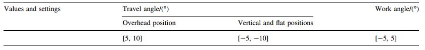
4 Robot welding path generationThe welding pass planning and adaptation module provides the position information for the robot welding torch to reach and follow. Figure 8 shows a procedure for generating robot paths for all the welding passes. The inclination angle associated with the welding work angle and the travel angle, both are defined with respect to the local coordinate frame, should be chosen in accordance with pipe welding procedures [21], as shown in Table 2. The centroid pass is first loaded to form the ''centreline'' to define the relative position offsets associated with all the filling passes, then the position information and welding torch inclination angles along each filling pass can be represented with respect to the robot origin coordinate frame. A beam search algorithm based path planner is adopted to find the optimal path with the minimum joint motion considering both path consistency and robot reachability [20]. For a given pass, the planner first generates a solution space that contains all the possible solutions for all the waypoints to account for both functional redundancy and different welding robot configurations (ϕ). If no consistent robot path exists for any robot configuration, the segment is further divided into two sub-segments. With a feasible joint solution space, a beam search strategy is then applied to determine the optimal robot path with minimum joint motion.

|
|
|
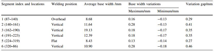
The proposed approach for robot arc welding pass planning and adaptation was implemented to fill up the welding groove of a full-size Y-type joint. The two pipes forming the Y-type workpiece have the same dimensions, each with an inner diameter 230 mm and an outer diameter 327 mm, and the intersecting angle between the two pipes is 45°. The groove model was obtained using a line-profile laser scanner, and digitalized into 360 cross sections. The plot of all the cross sections is shown in Fig. 2b. Table 3 summarizes the welding parameters obtained from a set of welding experiments, in which the workpiece is 500 mm × 100 mm × 12 mm mild steel plate and shielding gas is 80% argon + 20% CO2.

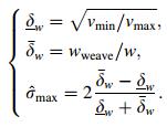
In this implementation, the maximum weave size is set to be 2/3 of the weld bead width. Based on the welding speed range as listed in Table 3, the maximum variation allowable in groove base width is 
|
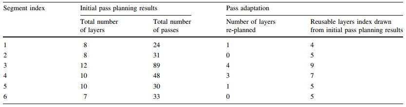
Table 5 summarizes the pass planning and adaptation results for the six segments. For initial pass planning results, it includes the total number of layers and total number of passes needed to fill-up each of the segments. It can be observed that segment 3 requires the most number of layers and passes as it yields the largest base width. The pass adaptation was carried out with the assumption the estimated weld thickness 

In this research, constant welding parameters are selected for generating the planned passes for the same layer. Table 6 summaries the number of passes of each layer and the welding parameters associated with the layer in groove segment 4, including arc voltage, welding current, CTWD and electrode feed rate. The welding parameters used for pass adaptation as in the scenario described in Table 5 are also included. Figures 9 and 10 depict the layout of the planned passes and the adaptation passes in one cross-section of the same groove segment.

|

|
|
|

|
|
|
It is noted in Table 6 that the number of passes of some of the layers are less than their previous layer, e.g., the 4th layer and the 6th and 7th layers in pass planning results, and the 4th and 5th layers in pass adapation results. This is due to the larger weave size incorporated in these layers with different sets of welding parameters used. With pass adaptation, the remaining un-filled groove requires seven layers of welding passes, in which the first three layers would need to be replanned, the subsequent four layers are transferred from the previous pass planning results for reuse.
5.2 Robot path generationWith the pass planning results, the pass locations are set to the robot path planner for optimal robot path generation. The example passes are selected to be the middle pass of the first layer in each segment. According to the pass planning results, the CTWD for all the six passes is 10 mm. Choosing the welding direction to be the up-hill direction, and the travel angle and the work angle based on Table 2, the robot paths for the first five segments are generated successfully, and the robot configurations for these paths are confined to 2, 0, 0, 0, 0 respectively, as shown in Figs. 11a–e. However, robot path generation for the pass in segment 6 has failed due to the path inconsistency, i.e., not a single robot configuration can be found such that the joint solutions of the sampled welding torch poses for all the waypoints along the pass are confined to this robot configuration. Therefore, segment 6 is equally divided into two sub-segments, with all the passes in segment 6 are divided accordingly. For the two passes divided from the middle pass of first layer of segment 6, the two robot paths are generated and optimized as shown in Figs. 11f, g, with the robot configuration confined to 3 and 0, respectively.

|
|
|
Multi-layer and multi-pass planning is crucial to the success of the subsequent welding robot motions in producing good quality welds in robotic welding of complex joints. This paper presents a theoretical study on welding pass planning and adaptation to weld a nonuniform and irregular groove for a Y-type joint. The groove is first divided into four segments based on the welding positions, and the groove segmentation is optimized based on the maximum allowable variations in the groove base width. For each resulting segment, a layerby-layer approach is presented to determine the number of layers and the number of passes in each layer. In this approach, a welding parameters adjustment scheme is proposed to maintain the number of passes of any unchanged layer across all the cross section of the segment. A pass adaptation method is developed in case there is a need for pass modification or re-planning after a number of layers of welding. With these passes, the associated robot paths are generated to achieve minimum accumulative joint motion subject to robot reachability and path consistency.
The proposed welding pass planning and adaptation approach can be further evaluated by transferring the planned data into welding robot controller codes in actual groove welding for validation. Improvement can be made to extend the pass planning method to be adaptable for different types of joints, e.g., T-type joints and K-type joints. More comprehensive welding experiments will be necessary such that a more accurate weld bead model can be achieved based on the collected welding parameters data. In addition to tuning the welding speed and weave size during pass planning, it would be useful to investigate the effect of changing other welding parameters, e.g., welding voltage and current, etc., to develop a more flexible robotic welding planning system.
Acknowledgements This research is supported by the Singapore A*STAR Agency for Science, Technology and SERC Industrial Robotic Programme on Robotic Welding of Complex Joint (Grant No. 1225100006).| 1. | Lorincz J (2015) Robotic welding fills skills gap with quality production. http://www.sme.org/MEMagazine/Article.aspx?id=8589936441. Accessed 26 Oct 2015 |
| 2. | Lin W, Luo H (2015) Robotic welding. In: Nee AYC (ed) Springer handbook of manufacturing engineering and technology: robotics and automation. Springer, London, pp 2404-2444 |
| 3. | Pires JN, Loureiro A, Bölmsjo G (2006) Welding robots: technology, system issues and application. Springer, London |
| 4. | Neto P, Mendes N(2013)Direct off-line robot programming via a common CAD package.Robot Auton Syst 61(8), 896-910 doi:10.1016/j.robot.2013.02.005 |
| 5. | Reinhart G, Munzert U, Vogl W(2008)A programming system for robot-based remote-laser-welding with conventional optics.Annals of the CIRP 57(1), 37-40 doi:10.1016/j.cirp.2008.03.120 |
| 6. | Fang HC, Ong SK, Nee AYC(2012)Interactive robot trajectory planning and simulation using augmented reality.Robot Comput Integr Manuf 28(2), 227-237 doi:10.1016/j.rcim.2011.09.003 |
| 7. | Fang HC, Ong SK, Nee AYC(2014)Novel AR-based interface for human-robot interaction and visualization.Adv Manuf 2(4), 275-288 doi:10.1007/s40436-014-0087-9 |
| 8. | Yang C, Ye Z, Chen Y, et al(2014)Multi-pass path planning for thick plate by DSAW based on vision sensor.Sensor Rev 34(4), 416-423 doi:10.1108/SR-04-2013-649 |
| 9. | Cao Y, Zhu S, Liang X, et al(2011)Overlapping model of beads and curve fitting of bead section for rapid manufacturing by robotic MAG welding process.Robot Comput Integr Manuf 27(3), 641-645 doi:10.1016/j.rcim.2010.11.002 |
| 10. | Xiong J, Zhang G, Gao H, et al(2013)Modeling of bead section profile and overlapping beads with experimental validation for robotic GMAW-based rapid manufacturing.Robot Comput Integr Manuf 29(2), 417-423 doi:10.1016/j.rcim.2012.09.011 |
| 11. | Suryakumar S, Karunakaran KP, Bernard A, et al(2011)Weld bead modeling and process optimization in hybrid layered manufacturing.Comput Aided Design 43(4), 331-344 doi:10.1016/j.cad.2011.01.006 |
| 12. | Ganjigatti JP, Pratihar DK, Choudhury R(2007)Global versus cluster-wise regression analyses for prediction of bead geometry in MIG welding process.J Mater Process Tech 189, 352-366 doi:10.1016/j.jmatprotec.2007.02.006 |
| 13. | Lee JI, Um KW(2000)Prediction of welding process parameters by prediction of back-bead geometry.J Mater Process Tech 108, 106-113 doi:10.1016/S0924-0136(00)00736-6 |
| 14. | Kim I, Son J, Park C, et al(2002)A study on prediction of bead height in robotic arc welding using a neural network.J Mater Process Tech 130, 130-131-229-234 |
| 15. | Nagesh DS, Datta GL(2002)Prediction of weld bead geometry and penetration in shielded metal-arc welding using artificial neural networks.J Mater Process Technol 123, 303-312 doi:10.1016/S0924-0136(02)00101-2 |
| 16. | Yan SJ, Ong SK, Nee AYC (2016) Optimal pass planning for robotic welding of large-dimension joints with deep grooves. In: Proceedings of 9th international conference on digital enterprise technology (det2016)—intelligent manufacturing in the knowledge economy era, 29-31 March 2016, Nanjing, China |
| 17. | Huo L, Baron L(2008)The joint-limits and singularity avoidance in robotic welding.Ind Robot 35(5), 456-464 doi:10.1108/01439910810893626 |
| 18. | Huo L, Baron L(2011)The self-adaptation of weights for jointlimits and singularity avoidances of functionally redundant robotic-task.Robot Comput Integr Manuf 27(2), 367-376 doi:10.1016/j.rcim.2010.08.004 |
| 19. | Ogbemhe J, Mpofu K(2015)Towards achieving a fully intelligent robotic arc welding: a review.Ind Robot 42(5), 475-484 doi:10.1108/IR-03-2015-0053 |
| 20. | Fang HC, Ong SK, Nee AYC(2016)Robot path planning optimization for welding complex joints.Int J Adv Manuf Technol doi:10.1007/s00170-016-9684-z |
| 21. | Rampaul H (2002) Pipe welding procedure, 2nd edn. Industrial Press, New York |