 2017, Vol. 5
The article information
- Azarhoushang Bahman, Zahedi Ali
- Laser conditioning and structuring of grinding tools-a review
- Advances in Manufacturing, 2017, 5(1): 35-49.
- http://dx.doi.org/10.1007/s40436-016-0167-0
-
Article history
- Received: 17 June, 2016
- Accepted: 21 December, 2016
- Published online: 28 February, 2017


Grinding is usually the last step in the machining of workpieces and components requiring high levels of precision and surface quality. Therefore the performance of a grinding tool has a great influence on the quality of the workpiece and the process efficiency. Wheel conditioning is one of the most important factors affecting the performance of the grinding tool [1-5].Owing to the mechanical and thermal loads on the cutting grains and bonding of the tool during the grinding process, the grinding tool is subjected to both macro-and micro-wear [6, 7]. The roundness and the profile of the tool change as a result of the macro wear. However, micro-wear leads to changes in the micro topography of the grinding tool. As a result, the grinding tool becomes dull (or sharp in exceptional cases) [8]. Accordingly, the selection of an appropriate conditioning process is a key prerequisite for ensuring an efficient grinding process.
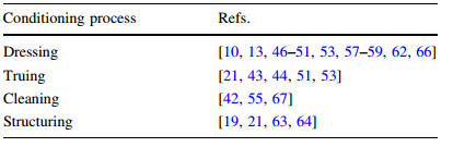
The tool conditioning is performed to generate the required form and profile accuracy, tool roundness and optimal micro topography of the grinding tool for a particular grinding process [4, 9]. The term "conditioning comprises truing, dressing and cleaning processes" [4, 8, 10]. The required form accuracy, profile and roundness of the grinding tool are attained by truing. Therefore, the truing process alters the macro topography of the grinding tool. Dressing generates a specific micro topography on the cutting surface of the grinding tool [6, 8, 9, 11]. With conventional grinding tools and vitrified bonded grinding tools both truing and dressing are usually carried out by the same process using diamond dressers, where the combination is commonly called dressing [11]. Cleaning is the regeneration of the micro topography of the grinding tool by removing the grinding chips and swarf, which penetrate into the pores of the grinding tool (loaded wheel) or which sometimes even become cold welded to the surfaces of the individual particles of grit (grinding tool clogging) [6, 10].
Based on the type of abrasive and bond, and the required profile of the grinding tool, different conditioning processes and tools may be utilized [6, 8]. The conditioning processes can be divided into four main groups according to their material removal mechanisms, namely mechanical, thermal, chemical and electrochemical (hybrid) conditioning processes [8, 12]. While mechanical process was the only type of conditioning process to be used in industry in the past, today there are other conditioning processes such as thermal, chemical and hybrid conditioning processes. However, mechanical conditioning, i.e., conditioning using diamond dressers or SiC/Al2O3 dressing tools, is still the most common conditioning process [8]. Nevertheless, the number of conditioning processes and their variants has grown continuously. In mechanical conditioning processes with diamond dressers, the abrasive grains and the bond are cut by the dresser [5, 8, 9]. However, aluminium oxide and silicon carbide dressing tools, which also belong to the mechanical conditioning tools, only cut and remove the bond [6, 8]. In non-mechanical conditioning the grains and bond of the grinding tool are eroded or ablated (instead of being mechanically cut) by applying electrochemical and thermal processes, such as laser conditioning, spark erosion electrical discharge machining (EDM), and electrochemical machining (ECM), electrolytic in process dressing [13-16].
Generally rotary diamond dressers are utilized for conditioning of vitrified bonded superabrasive (cubic boron nitride (cBN) and diamond) wheels [8, 17]. However, high dressing forces are generated in the contact zone between the dresser and the grinding tool, which cause wear to the dresser and partial fracture and/or crack propagation in the bond of the grinding tool. Owing to the gradually increasing wear of the dressing tool, the conditioning process loses its accuracy continuously after a certain number of dressing cycles, requiring that the dresser be periodically re-profiled and replaced after a defined time, which is associated both costly and time consuming. Compared to vitrified bonds, the conditioning of resin and metal bonded superabrasive grinding tools is even more complicated and time and cost intensive. For this purpose, either aluminium oxide and/or silicon carbide tools are generally used (in the form of a dressing wheel and as a mechanical conditioning process). However, the material removal rate of the conditioning process and the acquirable profile accuracy of the grinding tool are very limited [6, 8]. The dressing (sharpening) of the resin and metal bonds, i.e., influencing the micro topography of the grinding tool, directly in the grinding machine is generally possible using these conditioning tools [6, 8, 9, 18]. However, to alter the macro topography of the resin and metal bonded superabrasive grinding tools (truing) with alumina and/or silicon carbide conditioning wheels, the grinding tools are generally removed from the grinding spindle and mounted in a special conditioning machine. Thus the process is associated with high downtimes, additional costs, inaccuracies, low efficiency and limited profiling flexibility. Other disadvantages include the very high wear of the conditioning wheel and dust production in the case of dry machining, which is why a constant air suction in the conditioning machine is required [8].
Several researchers have considered the structuring as an additional conditioning step [4, 19-21]. The structuring of grinding tools is a novel method for reducing the cutting forces and temperatures and, hence, increasing the process efficiency by reducing the number of static, dynamic and kinematic cutting edges. This method has been the subject of several studies aiming to improve the cutting efficiency and coolant flow in the grinding zone [4, 17, 22]. The production of structures on the surface of the grinding tools using diamond dressers (mechanical method) is generally limited to the vitrified bonded tools [17, 21, 23-25]. Additionally, the possible structure patterns when utilizing diamond dressers are very limited. Furthermore, mechanical structuring is associated with the same technical limitations as the conditioning of superabrasive tools with diamond dressers, e.g., high wear of the dresser and, therefore, a continuous loss of the accuracy after each structuring cycle.
To overcome some of the technical limitations involved by mechanical conditioning and structuring of grinding tools, non-mechanical and unconventional conditioning processes such as laser conditioning have been developed to increase the process accuracy and flexibility while reducing costs and processing time. The application fields for machining with laser beams have been expanding in recent years with the advancement of the pulsed laser technology. The laser, as a fast, efficient, non-contact and versatile tool, is especially established in machining of difficult to cut materials such as high strength Ti/Ni based superalloys (e.g., Ti6Al4V [26-28], Inconel [29, 30]), super-hard materials (e.g., diamond [31, 32], cubic boron nitride [33]) and ceramics (e.g., Al2O3 [34, 35], SiC [34], Si3N4 [36, 37]). In addition to its high flexibility, a pulsed laser exhibits other positive characteristics such as targeted heat input, a small or even no heat-affected zone, force and contact free machining and simple spatial and temporal control [25]. Through the use of laser beams to condition the grinding tools, the disadvantages of mechanical conditioning and structuring processes can be overcome. Therefore, the use of a laser for the conditioning of superabrasive grinding tools, especially with metal, resin and hybrid bonds, can be beneficial. With the laser, grinding tools with various bond and abrasive types are conditioned reproducibly, with no wear and high accuracy. Furthermore over the long term, that is much more costefficient than the conventional methods [38].
However, laser conditioning and structuring has still not been extensively utilized in the industry. This review paper aims to address the material removal mechanism of the grinding tool in laser conditioning and structuring, describe the state of the art and discuss the technical barriers for its acceptance in manufacturing. This paper is organized into five sections. Following the introduction, Sect. 2 discusses the material removal mechanisms of laser conditioning. Section 3 summarizes the setups for laser conditioning and structuring. Experimental results are presented in Sect. 4. The technical challenges for the manufacturing application of laser conditioning are discussed in Sect. 5.
2 Material removal mechanisms of laser conditioningLaser conditioning is basically a thermal process which ablates the grinding wheel components to the extent required for the selected process, i.e., cleaning, sharpening, dressing and profiling. To limit the heat affected zone within the characteristic dimensions associated with the micro topography of common grinding wheels (grain/pore size and distance), most of the current literature address the application of pulsed lasers, which provide greater controllability of the thermal ablation process. The laser material interaction mechanism can be generally classified into three categories according to the laser pulse width tp, electron cooling time te and lattice heating time tl: continuous wave (CW) lasers, short pulsed lasers and ultrashort pulsed lasers [39]. If the pulse width is much larger than the electron-lattice coupling time (tp > 250 ms >> tl >> te), thermal ablation takes place mainly by the melting mechanism and the laser is said to be a CW laser [40]. The short pulsed lasers operate over smaller pulse width values in the order of nanoseconds, but the laser energy absorbed by the free electrons still has enough time to be transferred beyond the electrons and the lattice [40]. In the case of short pulsed lasers there is a slight amount of melting followed by rapid vaporization and the heat affected zone is smaller than that of CW laser [39]. The pulse width of ultrashort pulsed lasers is less than the electron cooling time (tp < te ≈ 1 ps << tl). In ultrashort pulsed laser treatment there is not enough time for the heat to be conducted into the solid medium. Therefore, provided the pulse energy exceeds the binding energy of the lattice, the lattice bond breaks instantaneously without any energy transfer to the neighbouring ions [39, 41].
Accordingly, a direct solid-vapor transition can be achieved with negligible melting and no residual debris. Considering the variations in the grinding wheel components (different types of abrasive grain and bond materials) and the demand for high controllability, the CW lasers are not suitable choices for precise grinding wheel conditioning. The development of the ultrashort pulsed lasers in recent years has enhanced the applicability of lasers in grinding. Besides the melt-free ablation, the ultrashort pulsed lasers are able to perform selective removal of the grinding wheel components [42, 43]. The determining factor affecting the selective ablation is the binding energy deviation among the radiated components. Figure 1 presents scanning electron microscope (SEM) images of two metal-bonded cBN and diamond abrasive surfaces, where the bonding material is selectively ablated by a picosecond Yb:YAG laser (with an average power of 50 W and peak pulse energy of 125 μJ) without inducing thermal damage to the grains. The cBN tool was irradiated with 50 μJ of pulse energy with a 10 mm/s scanning speed, while the diamond tool was irradiated with 37.5 μJ pulse energy and 20 mm/s scanning speed. The characterization of suitable laser treatment parameters (pulse energy and scanning speed) is discussed in Ref. [42], based on the desired conditioning process and the thermal properties of the wheel components. Accordingly, the range of conditioning processes from cleaning and sharpening (ablation of bonding material and chip loading, and the retention of abrasive grains) to dressing, structuring and profiling (controlled ablation of bonding material and abrasive grains) can be achieved with ultrashort pulsed lasers.

|
| Fig. 1 Selective ablation of metal-bonded cBN and diamond grinding tools |
The mechanism of laser processing further depends on the kinematics of the laser-workpiece interaction. The absorbed laser energy and the extent of beam reflection depend on the laser incidence angle over the wheel surface [44]. In addition, the desired conditioning process might require proper motion characteristics of the grinding wheel and the laser scanning. These requirements include tangential or radial radiation, grinding wheel angular position or velocity, axial motion and relative beam-workpiece speed (scanning speed) and can be provided by the machine axes and spindle and/or laser scanner.
3 Set-ups for laser conditioning and structuring of grinding toolsThe first laser conditioning setup was demonstrated in 1989 by Ramesh et al. [45, 46]. The setup consisted of a Nd:YAG laser (pulsed laser with a pulse width of around 460 μs and a pulse repetition rate of 15 Hz) and a fixture for mounting the grinding wheel, which also controlled the rotation and axial movement of the wheel. The laser beam was focused perpendicularly to the wheel surface through a plano-convex lens. The rotational speed of the wheel was synchronized with the laser pulse repetition rate, to achieve a slight overlap of the focused laser spots and form a continuous groove on the wheel periphery [46]. The setup was used for the dressing of a vitrified bond aluminium oxide grinding wheel.
The other developed laser conditioning setups are very similar to those of Ramesh. The main differences between the setups are the type of the laser system (e.g., Nd:YAG [10, 21, 46-53], CO2 [10, 54-56], Yb:YAG [21, 38, 42, 57], diode [54]), the laser beam transmitting system (i.e., mirrors [13, 21, 38, 42, 46-48, 51, 57] or fiber-optics [10, 43, 49, 50, 55, 58, 59]) and the laser beam position relative to the grinding tool's surface (i.e., tangential [10, 21, 43, 52, 53, 57, 60], perpendicular [10, 46-49, 51, 52, 55, 58-60] or on a defined incident angle [44]). The utilized laser beam can also be classified into CW laser [50, 58, 61], pulsed laser (pulse width C 1 μs) [10, 44, 46, 47, 49, 53, 55, 56, 62], short pulsed laser (1 μs[pulse width C 1 ns) [21, 43, 48, 51, 59, 63] and ultrashort pulsed laser (pulse width B 1 ns) [13, 19, 21, 38, 42, 57, 64]. The principle of the laser conditioning and structuring is illustrated in Fig. 2.

|
| Fig. 2 Laser conditioning and structuring of grinding tools |
Mirrors were chosen as the transmission system of the laser beam in Fig. 2, since the majority of the studies utilized this method given the higher flexibility relative to fiber laser heads. Moreover, the combined f-theta lens technology provides improved process controlling. The f-theta lenses exhibit a flat focal point, uniform spot diameter and a near spot velocity at the scan plane [65].
An additional difference between the utilized laser conditioning setups is the wheel mounting system. Generally, grinding tools were conditioned by laser outside of the grinding machine. In this case, either a special fixture was developed, consisting mainly of a motor (rotating the grinding tool), a flange (mounting the wheel on the spindle) and one or two translation axes [13, 19, 46, 48, 49, 59]. Otherwise the grinding tool was mounted on a lathe or laser machine [48, 51, 53, 64]. However, very few studies attempted to integrate the laser system directly into the grinding machine and condition the grinding tool directly on the spindle in order to reduce the downtime and increase the process efficiency [38, 43, 60, 62, 63].
4 Experimental resultsSeveral experiments (as summarized in Table 1) have addressed the laser conditioning and structuring of grinding tools. These experiments are described in this section according to the utilized process. When studying the effects of laser conditioning, some researchers used conventional grinding wheels (vitrified bonded aluminum oxide wheels) [46, 47, 50, 55, 56, 58, 67], while others used superabrasive (cBN and diamond) grinding tools.
|
The first attempts to study the effects of the laser dressing of grinding wheel surfaces were performed in the late 1980s by Ramesh and Radhakrishnan [46, 47]. They studied the interaction of laser pulses with a vitrified bonded alumina wheel (Φ250 mm 9 25 mm, AA60 K5 V8). A special fixture was developed to mount the grinding wheel, rotate it and move the wheel axially to generate the required helical path during laser dressing. A high power pulsed Nd:YAG laser was used to irradiate the surface of a rotating grinding wheel (the surface of the wheel was at the focal plane of the scanning lens), to which the laser beam was applied radially (perpendicularly) to the grinding wheel. Their study found that craters were formed by the laser irradiation, with these being surrounded by a recast layer exhibiting multiple cracks. The extent of damage had a direct relation with the intensity of the laser being used. It was reported that the laser dressed wheel led to an initial increase in the grinding forces owing to the rubbing action of the smooth recast molten layer (which was deposited on the wheel after laser dressing). However, this recast layer was removed as continuing grinding, resulting in a reduction of the grinding forces and an improvement of the workpiece surface finish [46]. With an appropriate selection of the laser intensity and its focusing conditions, the laser dressing generated a wheel surface topography, which could produce grinding results comparable to or better than those obtained with sharp diamond dressers [46]. Figure 3 shows the surface topography of the laser dressed grinding wheel.

|
| Fig. 3 Photograph of a the laser dressed wheel surface (Nd:YAG laser, pulse width 460 μs, focussed spot diameter 0.15 mm, wheel rotation speed: 0.25 r/min, pulse repetition rate: 15 Hz) and b the diamond dressed wheel surface (single point dresser) [46] |
Hosokawa et al. [49] investigated the laser dressing of a metal (bronze) bonded diamond grinding wheel (SD120N75M; 30 mm 9 30 mm 9 15 mm). The wheel surface was irradiated perpendicularly by a pulsed Nd: YAG laser (pulse width 2.5 μs). The irradiation removed the bond partially, which was subject to melting, vaporization and resolidification. To prevent the solidification of the molten bond on the wheel surface, an air jet was directed on the laser irradiated spot. The whole wheel surface was dressed and the appropriate grain protrusion height was generated by precise control of the laser pulse width, repetition rate and wheel rotation speed. Utilizing optimized laser parameters led to damage free diamond particles, where micro-cracks and graphitization of the diamond grains were not observed. HP-SiC was plungeground with conventionally dressed and laser dressed grinding wheels in order to examine the grinding performance of the laser dressed diamond wheel. Both grinding wheels (i.e., conventionally and laser dressed wheels, which had the same specification) indicated almost comparable forces, which were kept fairly constant up to V'w=50 mm3/mm (stock removed per unit width of cut). The surface topography changes of the laser dressed wheel before and after grinding are shown in Fig. 4. Figure 4 indicates that, the metal bond firmly holds the diamond grains during the grinding process and is not thermally deteriorated as a result of laser dressing [49].

|
| Fig. 4 Grinding wheel surface topography a after laser dressing, b after 100 grinding passes (cutting speed vs=25 m/s, workpiece speed vw=10 m/min, depth of cut ae=10 μm) [49] |
The above mentioned efforts into the application of a laser as a dressing tool were mainly based on the noncontact thermal ablation, which could resemble the action of a dressing tool. However, owing to the available laser devices, which were either CW or pulsed lasers with a rather large pulse width (microseconds or longer), it was not physically possible to distinguish between the grinding wheel components during the thermal ablation. Therefore, almost the same grinding force and surface roughness levels as those produced by conventional dressing methods could be achieved.
Zahedi and Azarhoushang [13, 66] compared the grinding performance of laser dressed and conventionally dressed grinding wheels. A Yb:YAG picosecond laser (pulse width: 10 ps, the maximum pulse energy: 125 μJ, repetition frequency: 400 kHz) was used for the laser dressing. The laser beam was conducted to a 2D-optical laser scanner through a set of mirrors and guides. A resin bonded cBN grinding wheel (B151C75BH-R, B1A1 D:100 T:15 X:5 H:20H7) was chosen for the cylindrical plunge grinding of hardened 100Cr6 bars (56 HRc). Considering the results of previously performed thermal analyses of the pulsed laser treatment [38, 42], and with regard to the thermal and mechanical properties of the cBN grains and the resin bond, the required pulse energy values for the effective ablation of the grains and the bond material were found to be about 62 μJ and 5 μJ, respectively. The gap between these energy values defines the range of pulse energies required for the treatment of bond material without damaging the cBN grains [13]. Therefore, the chosen pulse energy was 50 μJ and the rotational speed of the grinding wheel and the axial feed of the laser scanner were adjusted so that the relative scanning speed was 200 mm/s, while the pitch of the laser grooves was 50 μm. Accordingly, the groove depth was measured and found to be about 70 μm on the grinding wheel surface. Therefore, the grains (with an average size of about 151 μm) were not lost, while a sufficient amount of cutting edges and chip pockets were provided. At the same time an equivalent grinding wheel was dressed conventionally with a green SiC dressing wheel and sharpened using alumina blocks. Table 2 presents the laser and conventional dressing and cylindrical plunge grinding parameters.
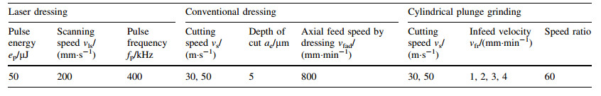
Images of the two processes and the resulting surfaces are presented in Fig. 5. Pullout of some grains on the surface of the conventionally dressed grinding wheel (marked with the red ellipse), and adjacent laser grooves on the laser-dressed grinding wheel can be seen in Fig. 5 [66].

|
| Fig. 5 Comparison between conventional and laser dressed grinding wheels a dressing procedure and the generated surface topography (before sharpening) of the conventionally dressed grinding wheel, b the laser dressed grinding wheel, c confocal images of the conventionally dressed wheel, and d laser-dressed grinding wheel [13] |
The conventionally dressed and sharpened wheel, compared to the laser dressed grinding wheel, incurred a higher grinding force and power [13]. Grinding with the laser dressed grinding wheel reduced the tangential force values up to 45%. It was reported that the more effective ablation of the bond material and retention of the grains (selective treatment of the components), as well as the more effective protrusion of the grains in the laser-dressed wheel were the main reasons for the reduction in the grinding force. Figure 6 presents the values of the specific grinding power and the tangential force resulting from plunge cylindrical grinding with both conventionally and laser dressed grinding wheels at various cutting speeds and infeed velocities [13].

|
| Fig. 6 a Grinding power, and b tangential force vs. infeed velocity for conventionally dressed and laser-dressed wheels [13] |
Other researchers also studied the effects of laser dressing on the grinding process. Timmer [52] used a Nd:YAG laser to dress both diamond and cBN grinding wheels with different bond types, both radially and tangentially relative to the wheel surface. Yung et al. [68] utilized an acousto-optical Q-switched Nd:YAG laser to dress a resin bond cBN wheel. A 10%-15% reduction of grinding force compared to conventional dressing, as well as a damage free wheel surface (no damaged cBN grains), was reported. Furthermore, the Q-switched laser exhibited a lower heat accumulation on the wheel surface relative to continuous wave laser processing. Dold et al. [57] studied the touch dressing of electroplated diamond wheels, using an ultrashort pulsed picosecond laser. Diamond grains could be cut without any remarkable graphitization effects. A comparison of the wheel topography before and after mechanical and laser touch dressing shows that the Abbott-Firestone-Curves are very similar, as surface roughness values (Ra and Rz). Rabiey et al. [59] investigated the potential of the laser dressing of hybrid bonded (a mixture of vitrified and metal bonds) grinding wheels using short pulsed fiber laser (pulse width: 125 ns). It was reported that lower grinding forces and consequently a lower specific energy and heat generation resulted from utilizing the laser dressed wheel, relative to the conventionally dressed (i.e., dressing with SiC wheels) one. However, the laser dressed wheel had a higher surface roughness and showed a higher radial wear.
The introduction of the short pulsed, and subsequently the ultrashort pulsed lasers to the grinding technology made it possible to control the thermal effects of the laser radiation on the individual components of different grinding wheel types. As a result, a wide range of laser-dressed grinding wheels, for which the grain protrusion and extent of thermal ablation could be selectively controlled, providing more favourable grinding force and workpiece surface characteristics than conventionally dressed wheels. Furthermore, the process time could be reduced and a higher dressing precision and repeatability could be achieved. As the mechanical dressing of superabrasive grinding wheels is challenging, and the deviation in the thermal properties of superabrasive wheel components (cBN/diamond grains and different bond types) is generally larger than that in conventional wheels, laser dressing can be especially considered as being a promising alternative for mechanical dressing for superabrasive grinding tools.
4.2 Laser truingThe truing of grinding tools using a laser enables the generation of complicated convex and concave profiles on the surface of the grinding tools (regardless of the abrasive and bond types) and hence defines the macroscopic form of the grinding wheel. Accordingly, it requires the highest degree of precision among all the laser-conditioning processes. The technical limitations of mechanical truing can be overcome by laser truing. Not only can laser conditioning ablate abrasive grains and bond from the grinding tool surface to generate the required geometry reproducibly and with high accuracy, it is much more cost-effective in the long-term than the conventional mechanical methods [38].
Researchers have examined mainly tangential laser irradiation on the grinding wheel surface, to define a precise geometry around the wheel periphery when performing laser truing [21, 43, 53, 60]. The tangential laser conditioning improves the controllability of the laser penetration depth into the wheel surface, and hence the profile accuracy. Kang et al. [53] conducted the truing of resin and metal bonded diamond wheels by utilizing pulsed Nd:YAG laser radiation on the grinding wheel surface. It was observed that the resin bond started to decompose, the bronze bond either melted or evaporated, and all damaged diamond grains were removed owing to the sputtering effects of the bond material. Wang et al. [44] utilized a pulsed YAG laser (pulse width 0.2-0.5 ms) with a maximum power of 400 W for the truing of a small vitrified cBN grinding wheel. The highest processing speed was 1 500 mm/min; the pulse frequency was varied from 100 Hz to 400 Hz, and the rotational speed of the wheel was maintained between 1 000 r/m and 2 000 r/m. The laser truing result (macro topography of the wheel) and the micro-profile after mechanical and laser processing are shown in Fig. 7. Characterization of the wheel surface after laser processing revealed (unlike the mechanical processing, Fig. 7c) resolidification of molten ceramic (see Fig. 7b), which exhibited a porous structure different from that of the original wheel surface. Additionally, using the energy balance equation, they developed a model to calculate several of the parameters required for laser truing. A new spatial distribution was obtained for the laser energy absorption at any position on a cylindrical surface between 0° and 90°. The presented model predicted the effect of processing parameters such as the incident angle (irradiation position) and focal offset on the absorbed energy and the effect of incident power and processing speed on the volume of material removed.

|
| Fig. 7 a Wheel surface profile after laser turning, b wheel surface conditions after laser processing, and c after mechanical preparation [44] |
Walter et al. [60] introduced an online (integrated into a five-axis machine) laser truing method for relatively small hybrid bonded cBN grinding tools (tool diameter, D: 10-15 mm, tool width, b: 10 mm, grit size B91) using a short pulsed fiber laser (pulse width\200 ns). The influence of the laser processing parameters on the truing performance was characterized and demonstration tools with different profile geometries were successfully produced. A minimum edge radius of redge\20 lmwas measured at the tip of a 90° profile edge on the ground workpiece, which was equivalent to the corner radius of the tool profile. The authors believe that the generation of such edge or corner qualities requires not only the removal of the bond material, but also the precision truing of the abrasive grains (considering the comparably large grain size), which cannot be realized by conventional dressing methods (e.g., by SiC wheels). Longterm grinding tests with the laser profiled tools (up grinding of hardened bearing steel 100Cr6; 60 HRc) demonstrated good in-service behaviour (constant grinding forces) and overall durability of the laser trued and profiled wheels.
The generation of larger macrostructures is also possible through tangential laser radiation and precise relative positioning of the laser beam and grinding wheel surface according to the desired profile form. In a recent research performed by KSF, a metal-bonded diamond grinding wheel (D76-C50-MB from Baerhausen) was used for profiling experiments to generate equilateral notch profiles with a depth of 2 mm and width of 4 mm. Figure 8 shows the grinding wheel during tangential laser ablation and the trace of the laser beam across the generated wheel profile. In this study, a picosecond Yb:YAG laser (pulse width: 10 ps, the maximum pulse energy: 125 μJ, repetition frequency: 400 kHz) was used with a pulse energy of 100 μJ and a scanning speed of 200 mm/s.

|
| Fig. 8 a Tangential laser ablation for profiling of a diamond grinding wheel, and b the scanned profile across the wheel periphery |
The topography of the two abreast profiles and the actual microscopic views of a generated notch are illustrated in Fig. 9. The retained diamond grains on the grinding wheel surface, which exhibit sufficient protrusion, are suitable situation for the material removal process. In the case of coarse grinding wheels with a larger average grain size, where higher protrusion of the grains would be required prior to grinding, the selective feature of laser treatment would be of great advantage. Accordingly, the above mentioned procedure can be followed by a finishing phase, where the laser power is set not to damage the grains and to remove the bond material.

|
| Fig. 9 a Confocal image of two notches generated with tangential laser profiling, and b the microscopic view of a laser-generated notch |
Chen et al. [43] designed and constructed an online (integrated in a surface grinding machine) tangential laser profiling device. The device consisted of a pulsed fiber laser (pulse width: 210 ns, average power: 40 W), a surface grinder, a motorized three-dimensional (3D) translation stage, laser displacement sensors and a laser power meter, and was used to true a coarse-grained bronze-bonded diamond grinding wheel (diameter 100 mm; width 10 mm; grain size 120#). Figure 10 shows the circular runout error of the grinding wheel surface as measured by a laser displacement sensor at three different cross-sections, which were equally spaced along the wheel axis before and after profiling. Utilizing the laser truing device, the mean circular runout and the axial gradient error of the grinding wheel surface reached 9.5 μm and 0.8 μm, respectively, thus satisfying the application requirements for a coarsegrained grinding wheel. However, the diamond grains on the surface of the profiled wheels were graphitized in an air atmosphere, where the relative intensity of the graphite characteristic peak (1 581.96 cm-1) in the Raman spectrum was 8.46 × 10³ a.u. The degree of graphitization decreased as a result of either blowing air or spraying a water mist from the side, such that the relative intensities of the graphite characteristic peaks dropped to 6.56 × 10³ a.u. and 5.82 × 10³ a.u., respectively.

|
| Fig. 10 Circular runout error at different locations on wheel surface a before, and b after profiling [43] |
Owing to the force-free material removal process, the relatively small diameter of the laser beam at its focus point and the small heat affected zone point to the use of an ultrashort pulsed lasers (owing to very low or no thermal damages on the surface of the grinding tool) is particularly interesting for precise, sharp-edged convex and concave profiles. The production of these kinds of profiles with mechanical truing, i.e., utilizing diamond dresser or SiC dressing wheels, is either very demanding or impossible.
It should be noted that, as the beam energy is not uniformly distributed over the cross-section of a normal laser beam, precise truing within a range of few micrometers could lead to a considerable loss of energy through the core of the beam, given that it barely comes into contact with the target surface. Accordingly, when using the same set of equipment laser truing is more time-consuming than other laser conditioning processes and could require laser units with a higher average power. This could be an economic barrier. Furthermore, in this aspect, short pulsed lasers might be preferable to the ultra-short pulsed ones, which are normally available with higher average powers with the same amount of investment and technical effort. However, highly attainable precision and controllability with ultrashort pulsed lasers could be required to reach a compromise between the two laser categories.
4.3 Laser cleaningLasers were used by several researchers [42, 55, 67] to clean ground chips and remove loaded materials from the surface of a grinding tool while causing minimal damage to the bond and abrasive grains. In term of the thermal properties, the bond material, cutting grains (abrasives) and ground chips are different, and the selective characteristics of ultrashort pulsed laser treatment would be a determining factor when cleaning of abrasive surfaces [42]. In the case of metal grinding, the cleaning takes place either by direct evaporation of the clogged chips, or by releasing the chips through the slight ablation of the surrounding bond material. However, unlike laser dressing, the only aim of laser cleaning is the ablation of the loaded and clogged materials (ground chips) from the surface of the grinding tool without any ablation of the bond material and/or the abrasives.
Chen et al. [55] used two types of pulsed lasers (a Nd:YAG laser with a pulse width range of 0.3-20 ms and a CO2 laser with a pulse width range of 0.3-80 ms) to explore the effects of laser irradiation on an aluminum oxide grinding wheel (grit size 46) with clogged metal chips (Inconel 718). The offset between the lens focus point and the wheel surface was introduced as one of the most important parameters affecting the laser cleaning and was changed between 5 mm and 105 mm. The process was influenced by the offset distance, since the laser power density decreases as the focus offset increases. The other influential factors were founded to be the laser energy and the pulse length. Effective laser cleaning of an aluminium oxide grinding wheel could be achieved with either a Nd:YAG laser or a CO2 laser as long as reasonable laser parameters were applied. However, as the CO2 laser had a longer wave length than the Nd:YAG laser, the energy absorption of the metal chips was consequently smaller. Therefore, a higher CO2 laser intensity was required to melt the metal chips.
Figure 11 shows the laser cleaning of a grinding wheel under different conditions and with a laser focus offset of 105 mm. The laser pulse was radiated continually onto the wheel surface (the surface shown on the left side of the figure) for about 3 min. Because of the heat accumulation, the temperature on the wheel surface was elevated, causing the wheel surface to be thermally damaged, even though the laser was not powerful enough to clean the clogged chips. The wheel surface became darker after being subjected to the laser radiation, which indicated that the wheel surface was damaged. The surface presented on the right side of the figure was radiated with the same laser power and a reduced focus offset distance and the laser pulses were radiated over the wheel surface for 3 min including continuous 5 s pulses and 25 s intervals. Because of the dissipated heat during the radiation intervals, the wheel surface was not damaged and the most of the metal chips were melted and removed owing to higher laser power density.

|
| Fig. 11 Nd:YAG laser cleaning of a rotating Al2O3 grinding wheel[55] |
Chen et al. [55] claimed that the high speed of the rotating wheel may help with the cleaning process by expelling the melted chips from the wheel surface. Laser cleaning experiments demonstrated that the cleaning effect depends not only on the laser parameters but also on the heat accumulation in the wheel during the laser cleaning process. A suitable irradiation interval could help to prevent any heat accumulation.
The thermal behaviour of the target surface is the key point affecting the laser cleaning of grinding wheels. Since ultra-short pulsed lasers provide the highest selectivity and controllability in the thermal ablation of radiated media, these laser types are the most suitable for the removal of clogged chips. In the case of vitrified or hybrid bonded grinding wheels, where the thermal properties of the chips and the bonding material lie in different ranges, the laser cleaning parameters could be set according to the thresholds of the workpiece material; however, in the case of resin and metal bonded wheels, a slight ablation of the bonding material would be inevitable, as their thermal properties would be lower or within the same range as the clogged chips. In this case, the laser cleaning would be accompanied by a sharpening effect.
4.4 Laser structuringLaser structuring is a new, non-mechanical preparation method for grinding tools. Using mainly ultrashort pulsed lasers precise micro-structures can be produced on the surface of grinding tools. The laser structuring of grinding tools, as an additional conditioning step, has been investigated by several researchers in order to enhance the cutting conditions [4, 19, 21, 38, 42, 64]. The structuring increases the percentage of active cutting grains and the chip thickness per grain and thereby the overall grinding efficiency [18].
Walter et al. [19, 64] presented a structuring method, utilizing a picosecond pulsed laser, which was found to be applicable to the micro scale structuring of superabrasive cBN grinding tools. The process allowed for the fabrication of arbitrary precise surface structures, enabling a high degree of geometrical and dimensional control of the generated features and, thus, the grinding behaviour of a tool [64]. SEM images and micro-Raman analysis indicated that the thermal impact of picosecond laser processing on the cBN abrasives could be neglected. Several structured cBN grinding tools with different patterns but equal active tool surface areas were fabricated, to study the influence of the pattern geometry on the grinding behaviour of the tools. The grinding performance and wear of the structured tools were tested and compared with a nonstructured (mechanically dressed and sharpened) tool [19]. The experiments (grinding of hardened bearing steel type 100Cr6; 60 HRc) were carried out at a constant specific material removal rate of Q'w=2 mm3/(mm·s) and a constant cutting velocity (vc=60 m/s). The corresponding normal grinding force Fn and surface roughness Ra values are shown in Fig. 12. For a non-structured benchmark tool, the measurements showed a steady rise in the cutting force. In contrast, the structured tools maintained relatively constant cutting forces throughout the entire test period. The force results were interpreted in combination with the workpiece roughness measurements. Figure 12a shows that the surface roughness produced with the non-structured tool remains constant after initial run-in. On the other hand, a steady increase of the workpiece roughness was observed with the structured tools [19].

|
| Fig. 12 a Normal grinding force and b workpiece roughness Ra vs. specific material removal for non-structured and different structured tools[19] |
Figure 13 compares SEM micrographs of the structured tool surfaces immediately after laser structuring (top) and after endurance tests with V'w=10 200 mm3/mm material removal, where structure traces are still visible on the worn tool surfaces [64]. However, comparison with the initial surface conditions reveals a considerable degradation of the original structures. The enhanced micro wear did not lead to significantly higher radial tool wear, relative to that of the non-structured tool. The authors claimed that there was a critical dimension for the features of a pattern (minimum size of abrasives clusters) below which an undesirably high level of degradation of the tool topography was inevitable.

|
| Fig. 13 SEM micrographs of a structured tool surface after laser structuring (top) and after wear test with V'w=10 200 mm3/mm material removal (bottom) at different magnifications [64] |
The investigations indicated that the pattern geometry had a strong effect on the grinding characteristics. Grinding forces could be reduced by up to 50% by using the laser structured tools. However, depending on the pattern type, a significant increase in the ground surface roughness and an increase in the radial wear of the structured tools were reported [19].
Given that high quality scanning in two and three dimensions is currently possible, laser structuring is a promising method for generating micro and macro structures over a vast range of grinding wheel types using different grain and bonding systems. Owing to the high controllability of the thermal effects, ultra-short pulsed lasers are the best choice for this purpose. The literatures provide some pointers on the types of structures and their corresponding performance. However, as an infinite number of structures at the micro and macro level could be generated, which could exhibit different lubricating and kinematic features, laser structuring could still be an open research topic for different applications. Long-term structure persistence and the corresponding wheel behaviour are the key factors affecting decisions about a desirable structure type.
5 Concluding remarksGiven the evidence in the available literature, it can be concluded that effective and reliable laser conditioning processes can be achieved using an appropriate laser type, and setup and process parameters. The selection of a laser type might be dependent on a compromise between the process time, precision and controllability. Short and ultrashort pulsed lasers provide outstanding ablation control, while the attainable treatment rate could be limited. This limitation could be a determining factor in profiling and truing processes, where the ablation rate is of a great significance. However, controllability is more important to the cleaning, dressing and structuring processes, for which the ultrashort pulsed lasers are the most suitable choices. With the current state of the laser technology nearly every grinding wheel conditioning process can be covered. However, the successful and efficient application of laser conditioning requires the characterization of process parameters, i.e., the laser pulse energy, scanning speed and pulse frequency in addition to the laser type. The establishment of process kinematics is another critical step towards this purpose, where the radiation strategies, i.e., normal or tangential ablation, and the setup mobility requirements should be defined. Accordingly, combined conditioning processes for achieving the desired micro and macro topographies on the grinding wheels could be realized.
Furthermore, the economic aspects of laser conditioning in terms of capital investment regarding the apparatus, qualified and trained personnel and process time have to be precisely evaluated. A better understanding of the laser conditioning process, to enable the optimal selection of the equipment and parameters, will widen the acceptance and application of lasers in grinding technology. Moreover, novel development in laser technology, which will support both academia and industry with more efficient and economically effective units will give further impetus to the promotion of the laser conditioning concept.
| 1. | Daneshi A, Jandaghi N, Tawakoli T (2014) Effect of dressing on internal cylindrical grinding. Procedia CIRP 14:37-41 |
| 2. | Rowe WB (2014) Grinding wheel dressing. In:Rowe WB (ed) Principles of modern grinding technology, 2nd edn. William Andrew, Waltham, pp 63-82 |
| 3. | Shih AJ(2000) An experimental investigation of rotary diamond truing and dressing of vitreous bond wheels for ceramic grinding. Int J Mach Tools Manuf 40, 1755-1774 doi:10.1016/S0890-6955(00)00022-5 |
| 4. | Wegener K, Hoffmeister HW, Karpuschewski B, et al(2011) Conditioning and monitoring of grinding wheels. CIRP Ann Manuf Technol 60, 757-777 doi:10.1016/j.cirp.2011.05.003 |
| 5. | Linke BS (2007) Wirkmechanismen beim Abrichten keramisch gebundener Schleifscheiben. Shaker, Aachen |
| 6. | Klocke F, Kuchle A (2009) Grinding, honing, lapping. Springer, Berlin |
| 7. | Kitzig H, Tawakoli T, Azarhoushang B(2016) A novel ultrasonicassisted dressing method of electroplated grinding wheels via stationary diamond dresser. Int J Adv Manuf Technol 86(1), 1-8 |
| 8. | Azarhoushang B, Rasifard A(2014) Das Abrichten als ein integraler Bestandteil des Schleifprozesses. Diam Bus 49, 66-73 |
| 9. | Marinescu ID (2007) Handbook of machining with grinding wheels. CRC, Boca Raton |
| 10. | Westkämper E(1995) Grinding assisted by Nd:YAG lasers. CIRP Ann Manuf Technol 44, 317-320 doi:10.1016/S0007-8506(07)62333-6 |
| 11. | Malkin S, Guo C (2008) Grinding technology:theory and applications of machining with abrasives. 2nd edn. Industrial Press, New York |
| 12. | Tawakoli T, Rasifard A (2011) Dressing of grinding wheels. In:Jackson JM, Davim PJ (eds) Machining with abrasives. Springer, US, Boston, pp 181-244 |
| 13. | Zahedi A, Azarhoushang B, Akbari J, et al(2016) Optimization and application of laser-dressed cBN grinding wheels. Adv Mater Res 1136, 90-96 doi:10.4028/www.scientific.net/AMR.1136 |
| 14. | Schöpf M, Beltrami I, Boccadoro M, et al(2001) ECDM (electro chemical discharge machining), a new method for trueing and dressing of metal bonded diamond grinding tools. CIRP Ann Manuf Technol 50, 125-128 doi:10.1016/S0007-8506(07)62086-1 |
| 15. | Wei C, Hu D, Xu K, et al(2011) Electrochemical discharge dressing of metal bond micro-grinding tools. Int J Mach Tools Manuf 51, 165-168 doi:10.1016/j.ijmachtools.2010.10.008 |
| 16. | Pavel R, Pavel M, Marinescu I(2004) Investigation of predressing time for ELID grinding technique. J Mater Process Technol 149, 591-596 doi:10.1016/j.jmatprotec.2004.02.026 |
| 17. | Rabiey M (2011) Dry grinding with CBN wheels, the effect of structuring. Dissertation, Universität Stuttgart |
| 18. | Azarhoushang B (2011) Intermittent grinding of ceramic matrix composites:unterbrochenes Schleifen von keramischen Faserverbundwerkstoffen. Dissertation, Stuttgart University, Shaker Publication |
| 19. | Walter C, Komischke T, Kuster F, et al(2014) Laser-structured grinding tools-generation of prototype patterns and performance evaluation. J Mater Process Technol 214, 951-961 doi:10.1016/j.jmatprotec.2013.11.015 |
| 20. | Tawakoli T (2014) Moderne schleiftechnologie und feinstbearbeitung 2014:neue entwicklungen und trends aus forschung und praxis. In:The seminar of moderne schleiftechnologie und feinstbearbeitung. Stuttgart, Volkan |
| 21. | Zahedi A, Azarhoushang B (2016) Strukturieren und profilieren mittels laser:moderne schleiftechnologie und feinstbearbeitung. In:The seminar of neue entwicklungen und trends aus forschung und praxis. Volkan |
| 22. | Tawakoli T, Rabiey M(2008) An innovative concept and its effects on wheel surface topography in dry grinding by resin and vitrified bond CBN wheel. Mach Sci Tech 12, 514-528 doi:10.1080/10910340802515989 |
| 23. | Tawakoli T, Heisel U, Lee DH, et al(2012) An experimental investigation on the characteristics of cylindrical plunge dry grinding with structured cBN wheels. Procedia CIRP 1, 399-403 doi:10.1016/j.procir.2012.04.071 |
| 24. | Nakayama K, Takagi J, Abe T(1977) Grinding wheel with helical grooves-an attempt to improve the grinding performance. CIRP Ann Manuf Technol 26, 133-138 |
| 25. | Azarhoushang B(2014) Das abrichten als integraler bestandteil des schleifprozesses:unkonventionelle Abrichtprozesse. Diam Bus 50, 82-89 |
| 26. | Kong MC, Miron CB, Axinte DA, et al(2012) On the relationship between the dynamics of the power density and workpiece surface texture in pulsed laser ablation. CIRP Ann Manuf Technol 61, 203-206 doi:10.1016/j.cirp.2012.03.038 |
| 27. | Yang J, Sun S, Brandt M, et al(2010) Experimental investigation and, 2010, 3D finite element prediction of the heat affected zone during laser assisted machining of Ti6Al4V alloy. J Mater Process Technol 210, 2215-2222 doi:10.1016/j.jmatprotec.2010.08.007 |
| 28. | Tangwarodomnukun V, Likhitangsuwat P, Tevinpibanphan O, et al(2015) Laser ablation of titanium alloy under a thin and flowing water layer. Int J Mach Tools Manuf 89, 14-28 doi:10.1016/j.ijmachtools.2014.10.013 |
| 29. | Ahn DG, Byun KW (2009) Influence of cutting parameters on surface characteristics of cut section in cutting of Inconel 718 sheet using CW Nd:YAG laser. Trans Nonferrous Metals Soc China 19:s32-s39 |
| 30. | Anderson M, Patwa R, Shin YC (2006) Laser-assisted machining of Inconel 718 with an economic analysis. Int J Mach Tools Manuf 46:1879-1891 |
| 31. | Fabis PM(1996) Laser machining of CVD diamond:chemical and structural alteration effects. Surf Coat Technol 82, 320-325 doi:10.1016/0257-8972(95)02774-2 |
| 32. | Butler-Smith PW, Axinte DA, Daine M(2011) Ordered diamond micro-arrays for ultra-precision grinding-an evaluation in Ti-6Al-4V. Int J Mach Tools Manuf 51, 54-66 doi:10.1016/j.ijmachtools.2010.09.006 |
| 33. | Kovalenko V, Yao J, Zhang Q, et al(2013) Laser milling of the intractable materials. Procedia CIRP 6, 504-509 doi:10.1016/j.procir.2013.03.068 |
| 34. | Samant AN, Dahotre NB(2009) Laser machining of structural ceramics-a review. J Eur Ceram Soc 29, 969-993 doi:10.1016/j.jeurceramsoc.2008.11.010 |
| 35. | Dhupal D, Doloi B, Bhattacharyya B(2008) Pulsed Nd:YAG laser turning of micro-groove on aluminum oxide ceramic (Al2O3). Int J Mach Tools Manuf 48, 236-248 doi:10.1016/j.ijmachtools.2007.08.016 |
| 36. | Fortunato A, Guerrini G, Melkote SN, et al(2015) A laser assisted hybrid process chain for high removal rate machining of sintered silicon nitride. CIRP Ann Manuf Technol 64, 189-192 doi:10.1016/j.cirp.2015.04.033 |
| 37. | Kang DW, Lee CM(2014) A study on the development of the laser-assisted milling process and a related constitutive equation for silicon nitride. CIRP Ann Manuf Technol 63, 109-112 doi:10.1016/j.cirp.2014.03.087 |
| 38. | Zahedi A, Tawakoli T, Akbari J, et al(2014) Conditioning of vitrified bond CBN grinding wheels using a picosecond laser. Adv Mater Res 1017, 573-579 doi:10.4028/www.scientific.net/AMR.1017 |
| 39. | Gadag S (2011) Studying the mechanism of micromachining by short pulsed laser. Southern Methodist University, Dallas |
| 40. | Giridhar MS, Seong K, Schuelzgen A, et al(2004) Femtosecond pulsed laser micromachining of glass substrates with application to microfluidic devices. Appl Opt 43, 4584-4589 doi:10.1364/AO.43.004584 |
| 41. | Varel H, Ashkenasi D, Rosenfeld A, et al(1997) Micromachining of quartz with ultrashort laser pulses. Appl Phys A 65, 367-373 doi:10.1007/s003390050593 |
| 42. | Zahedi A, Tawakoli T, Azarhoushang B, et al(2014) Picosecond laser treatment of metal-bonded CBN and diamond superabrasive surfaces. Int J Adv Manuf Technol 76, 1479-1491 |
| 43. | Chen G, Deng H, Zhou X, et al(2015) Online tangential laser profiling of coarse-grained bronze-bonded diamond wheels. Int J Adv Manuf Technol 79(9), 1477-1482 |
| 44. | Wang XY, Wu YB, Wang J et al (2005) Absorbed energy in laser truing of a small vitrified CBN grinding wheel. J Mater Process Technol 164-165:1128-1133 |
| 45. | Ramesh BN, Radhakrishnan V, Murti YVGS(1989) Investigations on laser dressing of grinding wheels-Part I:preliminary study. J Eng Ind 111, 244 doi:10.1115/1.3188756 |
| 46. | Ramesh BN, Radhakrishnan V(1989) Investigations on laser dressing of grinding wheels-Part II:grinding performance of a laser dressed aluminum oxide wheel. J Eng Ind 111, 253 doi:10.1115/1.3188757 |
| 47. | Ramesh BN, Radhakrishnan V(1995) Influence of dressing feed on the performance of laser dressed Al2O3 wheel in wet grinding. Int J Mach Tools Manuf 35, 661-671 doi:10.1016/0890-6955(95)93036-6 |
| 48. | Xie XZ, Chen GY, Li LJ(2004) Dressing of resin-bonded superabrasive grinding wheels by means of acousto-optic Q-switched pulsed Nd:YAG laser. Opt Laser Technol 36, 409-419 doi:10.1016/j.optlastec.2003.11.002 |
| 49. | Hosokawa A, Ueda T, Yunoki T(2006) Laser dressing of metal bonded diamond wheel. CIRP Ann Manuf Technol 55, 329-332 doi:10.1016/S0007-8506(07)60428-4 |
| 50. | Khangar AA, Kenik EA, Dahotre NB(2005) Microstructure and microtexture in laser-dressed alumina grinding wheel material. Ceram Int 31, 621-629 doi:10.1016/j.ceramint.2004.08.013 |
| 51. | Chen G, Mei L, Zhang B, et al(2010) Experiment and numerical simulation study on laser truing and dressing of bronze-bonded diamond wheel. Opt Lasers Eng 48, 295-304 doi:10.1016/j.optlaseng.2009.11.006 |
| 52. | Timmer JH (2001) Laserkonditionieren von CBN-und Diamantschleifscheiben. Dissertation, Braunschweig University, Vulkan-Verl., Essen |
| 53. | Kang RK, Yuan JT, Zhang YP et al (2001) Truing of diamond wheels by laser. KEM 202-203:137-142 |
| 54. | Chen M, Sun F, Lee Y, et al(2003) Laser-assisted grinding wheel dressing (ⅱ)-experimental researches. J Mater Sci Technol 19, 167-168 |
| 55. | Chen X, Feng ZJ, Pashby IR(2004) A study on laser cleaning of Al2O3 grinding wheels. KEM 257-258, 359-364 doi:10.4028/www.scientific.net/KEM.257-258 |
| 56. | Jackson MJ, Robinson GM, Chen X(2006) Laser surface preparation of vitrified grinding wheels. J Mater Eng Perform 15(2), 247-250 doi:10.1361/105994906X95968 |
| 57. | Dold C, Transchel R, Rabiey M, et al(2011) A study on laser touch dressing of electroplated diamond wheels using pulsed picosecond laser sources. CIRP Ann Manuf Technol 60, 363-366 doi:10.1016/j.cirp.2011.03.117 |
| 58. | Khangar A, Dahotre NB, Jackson MJ, et al(2006) Laser dressing of alumina grinding wheels. J Mater Eng Perform 15(2), 178-181 doi:10.1361/105994906X95832 |
| 59. | Rabiey M, Walter C, Kuster F, et al(2012) Dressing of hybrid bond CBN wheels using short-pulse fiber laser. SV-JME 58, 462-469 doi:10.5545/sv-jme |
| 60. | Walter C, Rabiey M, Warhanek M, et al(2012) Dressing and truing of hybrid bonded CBN grinding tools using a short-pulsed fibre laser. CIRP Ann Manuf Technol 61, 279-282 doi:10.1016/j.cirp.2012.03.001 |
| 61. | Khangar A, Dahotre NB(2005) Morphological modification in laser-dressed alumina grinding wheel material for microscale grinding. J Mater Process Technol 170, 1-10 doi:10.1016/j.jmatprotec.2005.04.087 |
| 62. | von Witzendorff P, Stompe M, Moalem A, et al(2014) Dicing of hard and brittle materials with on-machine laser-dressed metalbonded diamond blades. Precis Eng 38, 162-167 doi:10.1016/j.precisioneng.2013.08.007 |
| 63. | Guo B, Zhao Q, Fang X(2014) Precision grinding of optical glass with laser micro-structured coarse-grained diamond wheels. J Mater Process Technol 214, 1045-1051 doi:10.1016/j.jmatprotec.2013.12.013 |
| 64. | Walter C, Komischke T, Weingärtner E, et al(2014) Structuring of CBN grinding tools by ultrashort pulse laser ablation. Procedia CIRP 14, 31-36 doi:10.1016/j.procir.2014.03.093 |
| 65. | Stutz GE, Marshall GF (2012) Handbook of optical and laser scanning, 2nd edn. CRC, Boca Raton |
| 66. | Azarhoushang B, Zahedi A (2016) Laserabrichten von superabrasiven Schleifwerkzeugen:moderne schleiftechnologie und feinstbearbeitung. In:The Seminar of Neue Entwicklungen und Trends aus Forschung und Praxis, Volkan |
| 67. | Jackson MJ, Khangar A, Chen X, et al(2007) Laser cleaning and dressing of vitrified grinding wheels. J Mater Process Technol 185, 17-23 doi:10.1016/j.jmatprotec.2006.03.109 |
| 68. | Yung KC, Chen GY, Li LJ(2003) The laser dressing of resinbonded CBN wheels by a Q-switched Nd:YAG laser. Int J Adv Manuf Technol 22(7), 541-546 |