 2016, Vol. 4
The article information
- Ke-Feng Li, Yun-Hu Zhang, Chang-Jiang Song, Qi-Jie Zhai
- Numerical study of heat transfer and solidification behavior of gas-atomized Fe-6.5%Si (mass fraction) droplets
- Advances in Manufacturing, 2016, 4(2): 150-156
- http://dx.doi.org/10.1007/s40436-016-0141-x
-
Article history
- Received: 15 July 2015
- Accepted: 3 May 2016
- Published online: 1 June 2016


The Fe-6.5%Si (mass fraction) alloy possesses excellent soft magnetic properties [1, 2]. However,the workability of the alloy deteriorates drastically as the silicon content is above 3.5% (mass fraction),limiting its commercial applications in forms of alloy sheets. Various processing technologies have been investigated to overcome this problem [3, 4, 5, 6, 7].These technologies are neither environmentally friendly nor energy saving. The process of spray atomization and deposition,on the other hand,has attracted much attention as a near net shape technology with low cost. The studies on spray deposited Fe- 4.5% Si (mass fraction) [8, 9] and Fe-6.5% Si (mass fraction) [10] have shown the feasibility to produce the alloy sheets,and the relationships between the processing parameters in gas atomization and the formed microstructures are experimentally investigated. However,the challenges,i.e.,to improve the surface quality and reduce the thickness (below 0.3 mm) still remain,which hinders its applications. Fortunately,the successful fabrication of commercial Al alloys strip with good surface quality and adequate thickness by a novel spray-rolling processing[11],shedding light on the Fe-6.5% Si (mass fraction) alloy fabrication by the spray deposition process. The spray-rolling,by combining the spray forming and the twin-rolling casting,provides a very promising solution to overcome the difficulties mentioned above. The solid fraction of the deposition layer on the rollers surface is vital for the sheet quality [12],therefore the heat transfer and solidification of gas atomized droplet during the atomization must be investigated to precisely control and optimize the solid fraction of deposition layer. To our best knowledge,such kind of research on Fe-6.5% Si (mass fraction) alloy is rarely reported.
During atomization,the reduction of droplet volume leads to higher cooling rate and deeper nucleation undercooling [13]. Therefore the solidification process of droplet can be varied,and the solid fraction of the deposition layer changes dramatically. However,the process of droplet solidification during flight is not available experimentally. Therefore,in this work a numerical model,covering three solidification stages,namely liquid undercooling,nucleation and recalescence,and post-recalescence growth,is employed to investigate the heat transfer and solidification of gas atomized Fe-6.5% Si (mass fraction) droplet,which will guide and reduce the experimental matrix.
2 Model descriptions 2.1 Gas velocity decay and droplet velocityThe gas flow plays a critical role during the atomization process. The decay of axial gas velocity of atomization gas jet vg is given as [14]
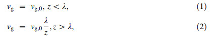
where vg,0,z and λ are the initial gas velocity at nozzle exit,the axial flight distance and the gas velocity decay coefficient  [15],respectively. In the gas flow,a droplet is accelerated or decelerated by the drag force depending on the velocity difference between droplet and gas. Supposing that the droplet is a rigid sphere and neglecting the interactions between droplets,the motion of an individual droplet along the axis can be expressed as [16]
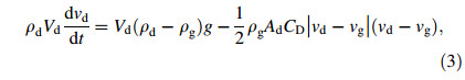
where νd,ρd,Vd,and Ad are the velocity,density,volume and cross-sectional area of the droplet,respectively. ρg and ν g are the density and the velocity of atomization gas,and g is the acceleration of gravity. The drag coefficient CD for a spherical droplet can be estimated by [17]
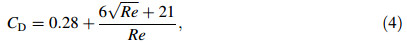
where Re is the Reynolds number, ; and μg is the gas dynamic viscosity.
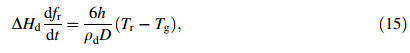
Once the melted alloys are disintegrated into droplets,they will release heat to the surrounding gas by convection and radiation. Here the temperature of the surrounding gas is set to be constant,Tg = 300 K,and the internal temperature gradient within a droplet is neglected. The heat conservation equation for the solidifying droplet is given by neglecting thermal radiation [18, 19]:
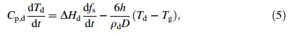
where C p,d-(1-fs)CL+CSfs,△Hd=△Hf-(CL-CS)(TL-Td)△Hf,fs,Td,ρdand D are the latent heat per unit mass,the solid fraction,the instantaneous temperature,the density,and the diameter of the droplet,respectively. The convectional heat transfer coefficient h is given as [20]
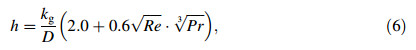
where k g is the thermal conductivity of the gas,Pr is the Prandtl number ,and Cp,g is the gas specific heat per unit mass.
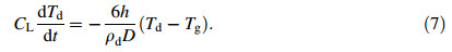
Firstly,the droplet cools down from the superheating temperature Ti to its nucleation temperature TN. During this period,the heat conservation equation during liquid state can be given as
The droplet can keep liquid state between its liquid line TL and the nucleation temperature TN. Thus the solidification does not start until the droplet temperature reaches its nucleation point. Therefore the prior undercooling before nucleation can be derived. In most cases,the heterogeneous nucleation predominates [21],

and the heterogeneous undercooling △Thet is expressed as [22]

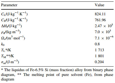
According to the nucleation theory proposed by Hirth [23],the maximum homogeneous undercooling of a droplet is formulated as
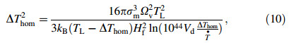
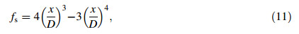
where σ m,Ωv and kB are the solid-liquid interface energy,atomic volume and Boltzmann constant,respectively. Once the nucleation starts,the droplet becomes a heat source itself due to the release of heat of fusion at the fast moving solid-liquid interface,and it drastically heats up the droplet nearly to its liquidus temperature TL. The recalescence ends,when the heat removes from the droplet surface are comparable with the heat of fusion released. The droplet solid fraction during recalescence is proposed by Levi [18] with an assumption that a spherical nucleus grows from the surface of a droplet,
and the growth rate can be approximately described as
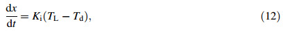
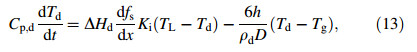
where Ki is the solid-liquid interface mobility,having a magnitude of 0.01 m/(s·K) [24]. By combining the Eqs. (6),(12),and (13),the energy conservation equation can be formulated as
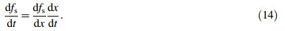
where the growth rate of solid can be written as
At the end of recalescence,the heat balance equation can be obtained by setting
where fr and Tr are the solid fraction and temperature of the droplet at the end of recalescence,respectively.
2.3.3 Segregated solidificationAfter recalescence,under the assumption of linear slopes of liquidus and solidus temperature the solid fraction can be approximated according to the Scheil’s equation [25]
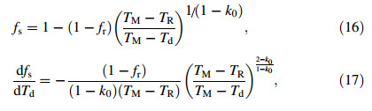
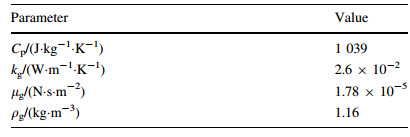
where TM is the melting point of the pure solvent (here the solvent is Fe) and k0 is the equilibrium partition coefficient. All the relevant parameters for the nitrogen gas and the alloy are given in Tables 1 and 2. The gas temperature is set at a constant value of 300 K.
The gas and droplets velocities are given in Fig. 1a,and the initial gas velocity is set at vg,0 = 200 m/s. Smaller droplets reach larger maximum velocities at shorter distances than the larger ones because the former are easier to be accelerated by the gas. For example,the maximum velocities are 102.5 m/s and 43 m/s for 20 lm and 120 lm droplets at distances of 0.090 m and 0.173 m,respectively. For droplets larger than 80 lm,the velocities do not change significantly by the drag force of the gas because the decelerations of larger droplets are less important compared to the gravity force. Figure 1b displays the convective heat transfer coefficients as a function of flight distance for droplets of different size. The turning points indicate that the relative velocities between gas and droplet are zero,thus the heat transfer coefficients reach their minimum,h=2kg/D.
 |
| Fig. 1 Simulated a gas and droplets velocities and b heat transfer coefficients as a function of droplet flight distance for the droplets with different sizes |
The droplet nucleation undercoolings are calculated to be 302,291,255,160 and 39 K by Eqs. (8) to (10) for 20,30,50,80 and 120 lm droplets,respectively. After the droplets are undercooled to their nucleation points,the solidification starts at very high speed and the droplet temperatures reach 1 678,1 690,1 698,1 699 and 1 699 K due to the release heat of fusion. This means that the solid fractions formed during recalescence are much larger for droplets below 30 lm,because they do not reach the liquidus temperature during recalescence,thus the re-melting can be avoided. With the simulated heat transfer and the undercoolings,one can easily obtain the temperature-flight distance relations and the temperature change rates of different sized droplets,as demonstrated in Fig. 2. The initial cooling rates of fully liquid droplets increase from 6.8 × 10⁴ K/s to 1 × 10⁶ K/s,while the droplet sizes decrease from 120 μm to 20 μm in diameter. At the recalescence stage,the heating rate ranges from 2.3 × 10⁵ K/s to 4.7 × 10⁷ K/s due to the heat of fusion released. Then the droplets cool down again during segregated solidification,with the cooling rates spanning from 4.8 × 10⁴ K/s to 7 × 10⁵ K/s.
 |
| Fig. 2 Simulated a temperature profiles and b cooling rates as a function of the flight distances for the droplets with different sizes |
Figure 3 shows the solid fractions of different sized droplets on the flight distance. For 20 lm and 30 lm droplets,the solid fractions at the end of recalescence are 0.992 and 0.990,respectively. The droplets are almost fully solidified at flight distances of about 0.023 m and 0.042 m,while the solid fractions of 50 lm,80 lm and 120 lm droplets are 0.880,0.540 and 0.370 at flight distances 0.118 m,0.165 m and 0.106 m. The results show that at the flight distance of 0.2 m,the droplets smaller than 120 lm are almost fully solidified.
 |
| Fig. 3 Simulated solid fractions as a function of the flight distance for the droplets with different sizes |
Fe-6.5% Si (mass fraction) alloy powders are fabricated using 99.9% Fe and 99.9% Si,the atomization gas is nitrogen at a pressure of (1.8-2.2) MPa (vg,0 ≈ 200 m/s). The melt overheating is about 150 K above the liquidus. The produced powders are then sieved for further analyses:<38 μm,38-53 μm,53-63 μm,63-75 μm,75-105 μm,105-150 μm and[150 μm. The median size is measured to be d50 = 127 μm.
In this part,the observed secondary dendrite arm spacing (SDAS),together with calculated cooling rate,are incorporated to derive the cooling rate dependence of SDAS,which is evaluated by the corresponding values reported for various Fe-based alloys. Figure 4 shows the surface morphologies of atomized particles,typical dendrite morphologies are observed. As can be seen,the SDAS decreases with the decreasing of droplet size. The relationship of SDAS and the droplet size is then characterized in Fig. 5,and the plotted curve follows the equation
 |
| Fig. 4 Surface dendrite growth morphologies of the gas atomized particles with different sizes |
 |
| Fig. 5 Experimental (dots) and fitting (dot line) results of the SDAS as a function of particle size (The inset is the surface morphology of a 55 μm particle and its SDAS measurement) |

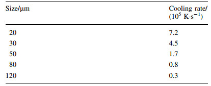
As indicated in Fig. 2b,the cooling rates are not constant during flight. Because the secondary dendrite arms are formed at the post-recalescence (segregation) stage [26],the cooling rates of the droplets are averaged during this stage,as listed in Table 3. Figure 6 gives the dependence of average cooling rate on particle size,and the following relationship can be derived [27]
 |
| Fig. 6 Simulated (round dots) and fitted (solid line) average cooling rates during solidification for droplets with different sizes |

By the combination of Eqs. (19) and (20),one can easily deduce the following relationship between SDAS and the cooling rate,

This result is in excellent agreement with the wellestablished formulation, [26]. In fact,the experimentally obtained pre-constants β and the exponents for various kinds of steels in rapid solidification range from 35 to 143 and from -0.34 to -0.45 [28],respectively. For example,in rapid solidified Fe-18Cr-1C alloy [29] and M2 steel [30],the preconstant β and exponent are 60,-0.41 and 59,-0.34,respectively. These reported values strongly support the simulation results of this work. The cooling rate dependence of the droplet size calculated from the model is reasonable,which means that the model itself can be used to predict the solidification process of gas atomized Fe-6.5% Si (mass fraction) alloy.
In this work,to better understand the solidification process of gas atomized Fe-6.5% Si (mass fraction) droplets,an integral numerical model is employed and experiment is conducted. The melt undercoolings vary from 300 K to 39 K when droplet size increases from 20 lm to 120 lm. The solid fraction of the droplet as a function of flight distance is discussed for different particle sizes. It is found that smaller droplets can finish the solidification process at shorter flight distance. The cooling rate is calculated and verified by the SDAS measurement. By comparing with experimental results from other rapid solidified Fe-based alloys,excellent agreement is presented,showing the validity of the numerical model.
Acknowledgments This work was financially supported by the National Natural Science Foundation of China (Grant No. 51574162). The authors would like to express sincere thanks for their support.| 1. | Goertz M (1951) Iron-silicon alloys heat treated in a magnetic field. J Appl Phys 22(7):964-965 |
| 2. | Carr WJ, Smoluchowski R Jr (1951) The magnetostriction of single crystals of iron-silicon alloys. Phys Rev 83(6):1236-1243 |
| 3. | Takada Y, Abe M, Masuda S et al (1988) Commercial scale production of Fe-6.5 wt.% Si sheet and its magnetic properties. J Appl Phys 64(10):5367-5369 |
| 4. | Yamashiro Y, Yoshida Y, Teshima N et al (1982) Thickness dependence of magnetic properties in rapidly quenched 6.5 percent silicon iron thin ribbons. IEEE Trans Magn 18(6):1421-1423 |
| 5. | Kim KN, Pan LM, Lin JP et al (2004) The effect of boron content on the processing for Fe-6.5 wt% Si electrical steel sheets. J Magn Magn Mater 277(3):331-336 |
| 6. | Li R, Shen Q, Zhang L et al (2004) Magnetic properties of high silicon iron sheet fabricated by direct powder rolling. J Magn Magn Mater 281(2-3):135-139 |
| 7. | Fang XS, Liang Y, Ye F et al (2012) Cold rolled Fe-6.5 wt.% Si alloy foils with high magnetic induction. J Appl Phys 111(9):094913-094914 |
| 8. | Yang L, Tian C, Zhang Y et al (2001) Spray forming processing of Fe-Si alloy deposit. Powder Metall Technol 19(6):354-357 |
| 9. | Yang L, Tian C (2002) Microstructure and properties of Fe-4.5 wt% Si steel produced by spray forming and rolling. Mater Sci Technol 10(1):55-58 |
| 10. | Bolfarini C, Silva MCA, Jorge AM Jr et al (2008) Magnetic properties of spray-formed Fe-6.5% Si and Fe-6.5% Si-1.0% Al after rolling and heat treatment. J Magn Magn Mater 320(20):e653-e656 |
| 11. | McHugh KM, Delplanque JP, Lavernia EJ et al (2004) Spray rolling aluminum alloy strip. Mater Sci Eng A 383(1):96-106 |
| 12. | McHugh KM, Lin Y, Zhou Y et al (2008) Microstructure evolution during spray rolling and heat treatment of 2124 Al. Mater Sci Eng A 477(1-2):26-34 |
| 13. | Perepezko JH (1984) Nucleation in undercooled liquids. Mater Sci Eng 65(1):125-135 |
| 14. | Saad MA (1985) Compressible fluid flow. Prentice-Hall, Englewood Cliffs |
| 15. | Lee ES, Ahn S (1994) Solidification progress and heat transfer analysis of gas-atomized alloy droplets during spray forming. Acta Metall Mater 42(9):3231-3243 |
| 16. | Lu QQ, Fontaine JR, Aubertin G (1993) Numerical study of the solid particle motion in grid-generated turbulent flows. Int J Heat Mass Transf 36(1):79-87 |
| 17. | Clift R, Grace JR, Weber ME (2005) Bubbles drops and particles. Dover Publications Incorporated, New York |
| 18. | Levi CG, Mehrabian R (1982) Heat flow during rapid solidification of undercooled metal droplets. Metall Trans A 13(2):221-234 |
| 19. | Levi CG, Mehrbian R (1980) Heat flow in atomized metal droplets. Metall Trans B 11(1):21-27 |
| 20. | Ranz WE, Marshall JR (1952) Evaporation from drops:part 1. Chem Eng Prog 48:141-146 |
| 21. | Zeoli N, Gu S (2006) Numerical modelling of droplet break-up for gas atomisation. Comput Mater Sci 38(2):282-292 |
| 22. | Mathur P, Apelian D, Lawley A (1989) Analysis of the spray deposition process. Acta Metall 37(2):429-443 |
| 23. | Hirth JP (1978) Nucleation, undercooling and homogeneous structures in rapidly solidified powders. Metall Trans A 9(3):401-404 |
| 24. | Bergmann D, Fritsching U, Bauckhage K (2000) A mathematical model for cooling and rapid solidification of molten metal droplets. Int J Therm Sci 39(1):53-62 |
| 25. | Brody HD, Flemings MC (1966) Solute redistribution in dendritic solidification. Trans Metall Soc AIME 5:615-623 |
| 26. | Kurz W, Fisher DJ (1998) Fundamentals of solidification. Trans Tech Publications, Uetikon-Zuerich |
| 27. | Pryds NH, Hattel JH, Thorborg J (1999) A quasi-stationary numerical model of atomized metal droplets. II:prediction and assessment. Model Simul Mater Sci Eng 7(3):431-446 |
| 28. | Löser W, Thiem S, Jurisch M (1993) Solidification modelling of microstructures in near-net-shape casting of steels. Mater Sci Eng A 173(1-2):323-326 |
| 29. | Sahm PR, Jones H, Adam C (2012) Science and technology of the undercooled melt:rapid solidification materials and technologies. Springer Science & Business Media, London |
| 30. | Morris DG (1982) Rapid-solidification phenomena. Met Sci 16(10):457-464 |