 2015, Vol. 3
The article information
- Ali Mamedov, Ismail Lazoglu
- Micro ball-end milling of freeform titanium parts
- Advances in Manufacturing, 2015, 3(4): 263-268
- http://dx.doi.org/10.1007/s40436-015-0123-4
-
Article history
- Received: 27 April 2015
- Accepted: 29 September 2015
- Published online: 20 October 2015


Micro machining has a growing market in biomedical applications,automotive applications,aerospace and jewelry industries. It can be implemented in a large spectrum of materials. However,due to their superior properties such as high strength to weight ratios and low thermal conductivities,biocompatibilities,etc.,titanium alloys are very commonly used in advanced engineering materials. Most of the small-sized freeform titanium parts are machined using the micro ball-end milling before polishing and other surface treatments. As the demands for parts with complex shape increase,the necessity of enhancing the efficiency and productivity also increases Some examples for engineering parts with complex freeform geometry like molds,implants and impellers are shown in Fig. 1.
 |
| Fig. 1Examples for engineering parts with complex freeform geometry a finger joint implants from DePuySynthes Joint Reconstruction Inc., b impeller of the blood pump from Jarvik Heart, c reconstructive joint implants from Wright Medical Technology Inc., d miniature impeller, e miniature freeform surface, f mold of special focusing lens |
In order to perform a precise and reliable feedrate scheduling algorithm,the kinematics and mechanics of milling process should be modeled. For this reason,several groups of researchers worked on the kinematics modeling of the micro milling cutting process. Vogler et al. [1] and Waldorf et al. [2] developed the shear plane plasticity model. Based on these studies,Jun et al. [3] and Fang [4] developed more complex plasticity models, which covered the elastic recovery of plowed material. Fang and Jawahir [5] proposed a generalized slip-line field model to predict shearing and plowing forces. Jin and Altintas [6] developed a slip-line field model,to estimate the stress variation in shear zones and relate it to temperature and tool edge radius effect. A mechanistic force model proposed by Park and Malekian [7] considered both the shearing and plowing dominant cutting regimes and related plowed area to volume of the plowed material due to the effect of the tool edge radius. Manufacturing with high productivity and low cycle time was always desired by engineers. As a result,some researchers investigated feedrate scheduling technique,which kept resultant cutting forces at the maximum limit along the tool path in order to decrease the machining time and increase productivity. Erdim et al. [8] investigated different techniques and stated that the force-based technique was more applicable rather than the material removal rate based scheduling technique. Ko and Cho [9] investigated the feedrate scheduling for 3D ball-end milling.
Layegh et al. [10] presented an offline force control and feedrate scheduling method for 5-axis milling operations. In this research,a mathematical model to predict cutting forces during micro milling is presented. The presented model considers the mechanical effects of machining parameters in ball-end milling. The force-based feedrate scheduling (FFS) technique is implemented on the titanium part with a freeform surface geometry.
2 Kinematics of the process 2.1 Cutter-workpiece engagement calculationThe cutter-workpiece engagement calculation plays an important role in modeling of the kinematics of the cutting process. The cutter-workpiece calculation method based on solid modeler is employed in the present paper. In this method,the contact surface between tool and workpiece is calculated at each cutter location point. Later,from the cutter location file,the swept volume of the tool is calculated and subtracted from a blank workpiece. After subtraction,the entrance and exit angles of each discrete cutting disc are calculated. The cutter engagement input for force model is formed from the calculated entrance and exit angles. A detailed explanation of the employed cutter-workpiece engagement model was presented by Yigit et al. [11]. The sample contact regions for cutter location point and machined part are shown in Fig. 2.
 |
| Fig. 2Sample contact region for cutter location point and machined part. a CAD model of freeform surface, b CAM simulation and toolworkpiece contact region, c machined part after roughing, d machined part after finishing |
Modeling of micro milling forces is an important aspect in order to control and understand the kinematics of cutting process. It is known that the kinematics of micro milling process is different from that of conventional machining operations. The most distinctive difference is the presence of the size effect,which occurs when the edge radius of the micro tool is in the same range with uncut chip thickness. This phenomenon results in plowing of the workpiece material. The following method for cutting force modeling of ball-end mill is used. The ball-end mill is discretized into the finite number of flat end mills according to a local radius,as shown in Fig. 3,and forces calculated at each disk are integrated to calculate the total cutting force components.
 |
| Fig. 3a Ball-end mill with discrete discs, b schematic view of discrete discs |
From the prior research,it is clear that the chip thickness is an important aspect for the cutting force estimation. The expression of the chip thickness for micro milling,where the ratio of feed per tooth to tool radius is higher than that in conventional milling,was proposed by Li et al. [12]. The same chip thickness model is employed in the proposed force prediction model. Accordingly,the instantaneous chip load for the kth disk considering the run-out [13] can be written as
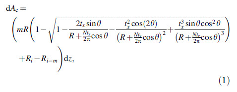
where Ri is the rotation radius of an arbitrary element of the cutting edge i,and

R is the local radius of the tool,N the number of flutes,tx the feed per tooth,ρ the run-out amplitude,λ the run-out angle,β the helix angle,z the axial position of the discrete element of the cutting edge,Ri-m the current tooth i removing the material left by the mth previous tooth,and θ the rotational angle.
Formation of the chip during the micro milling depends on the uncut chip thickness. The process is becoming plowing dominant when the actual uncut chip thickness is less than the minimum uncut chip thickness. However,if the actual uncut chip thickness is greater than the minimum uncut chip thickness,the cutting process becomes shear dominant. The formulation of differential cutting forces with shearing and plowing components is given as
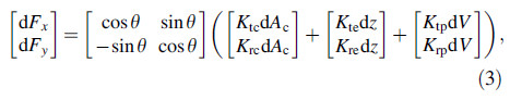
where dFx and dFy are differential cutting forces in the feed x and cross-feed y directions; θ is the instantaneous immersion angle of the discrete point; Ktc and Krc are cutting coefficients; Kte and Kre are edge coefficients; Ktp and Krp are plowing coefficients; dV denotes the volume of plowed material and dz is the differential axial depth of cut. More detailed information on modeling was presented in a previously developed force model [14]. Total cutting forces can be determined by integrating the differential cutting forces in the individual discrete elements along the cutting edges.
2.3 Feedrate scheduling techniqueBecause of the complex geometry of freeform surfaces, operators tend to select conservative cutting parameters to avoid tool deflections,tool breakage and low surface quality. On the other hand,manufacturing with higher feedrates will result in an increase of productivity. It is possible to increase feedrate while staying in a safe region by considering kinematics of the cutting process. The keynote papers on scheduling technique were presented in Refs. [15, 16, 17]. This technique maintains resultant cutting force at a desired value for all cutter location (CL) points. Scheduled feedrate for each CL point can be calculated as [10]

where F1;i is the estimated resultant force at point i for feed f1 and F2;i for feed f2; Flim;i denotes the threshold value of resultant cutting force for the ith CL point. Scheduled feedrate is calculated from process simulation at different constant feedrates by adjusting resultant cutting force at each CL point,as shown in Fig. 4.
 |
| Fig. 4Sample of NC code with scheduled feedrate for the 13th path of the second layer |
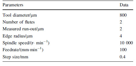
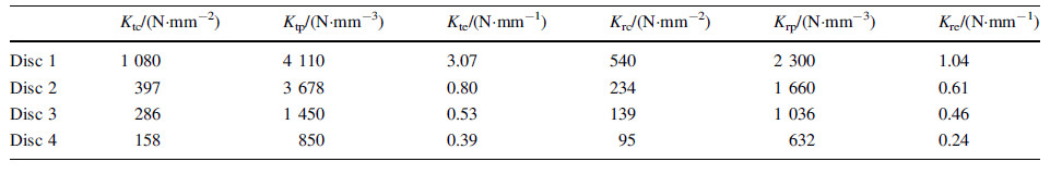
Experiments were performed on Mori Seiki NMV 5000DCG 5-axis CNC milling machine using 800 lm diameter two fluted tungsten carbide micro ball-end mill. A freeform geometry was machined on Ti-6Al-4V grade 5 titanium alloy workpiece and cutting forces were measured with a table type mini dynamometer. The experimental setup and freeform part geometry used for validation of proposed models are shown in Figs. 5 and 6. The cutting conditions and tool specifications are presented in Table 1 and cutting coefficients for Ti-6Al-4V with tungsten carbide ball-end mill are presented in Table 2.
 |
| Fig. 5Experimental setup |
 |
| Fig. 6Cutting tool path for entire sculptured geometry |
Cutting tool path for the entire sculptured surface with the size of 6 mm × 7 mm is shown in Fig. 6. The machining was performed in 6 layers with 15 paths in each layer. Experimental force measurements were performed in order to validate the proposed force model. Estimated and measured forces in x and y directions for the 13th path in the second layer are shown in Fig. 7. The prediction accuracy of the proposed force model can be seen in Fig. 8. The feedrate scheduling technique was validated through comparison of the set target value of resultant force with experiments for scheduling implemented case. Experiments were performed on the freeform surface. The feedrate scheduling algorithm calculates appropriate feedrate value for each CL point according to the selected threshold value of resultant cutting force. The threshold cutting force as it was the limitation for resultant cutting force,and it is set as Flim = 30 N which is the maximum resultant cutting force for unscheduled milling.
 |
| Fig. 7Cutting forces in the feed (x) and cross-feed (y) directions for single path |
 |
| Fig. 8Cutting forces in the feed (x) and cross-feed (y) directions |
From Figs. 9 and 10,it can be seen that if the feedrate is kept constant along the tool path,the resultant cutting force is varying. In the constant feedrate case,the time to complete one roughing path across the freeform part is 2.5 s. When the FFS technique is implemented in roughing by varying the feedrate according to the algorithm,the machining time is decreased to 1.23 s for one tool path across the freeform surface. In the FFS case,the resultant cutting forces were also kept below 30 N,without exceeding the set target value. This example demonstrates that implementation of the force-based feedrate scheduling technique has a potential to decrease the cycle time in the micro milling of freeform surfaces.
 |
| Fig. 9Resultant cutting force magnitudes along the tool path for the constant and scheduled feedrate cases |
 |
| Fig. 10Illustration of the scheduled and constant feedrate values Micro ball-end milling of freeform titanium parts 267 123 |
A feedrate scheduling technique and analytical model for predicting micro milling cutting forces for ball-end milling were presented. The force model precisely estimates the micro milling cutting forces formed by both shearing and plowing cutting mechanisms. The main focus was on scheduling of feed-rate during micro ball-end milling. It is seen that the proposed technique decreases cycle time for an entire cutting process,which could result in productivity increase. Through the experiments,it was seen that both force and feed rate scheduling model simulation results were in a good agreement with experiments.
Acknowledgements The authors would like to acknowledge the Scientific and Technological Research Council of Turkey Project Support (TUBITAK Grant No. MAG110M697) and TUBITAK International Research Fellowship for Prof. Ismail Lazoglu. The authors also would like to thank Koc¸ University Surface Science and Technology Center,Sandvik Coromant,Toolex,Nikken and Tandem for their kind supports for the research.| 1. | Vogler M, Kapoor S, DeVor R (2004) On the modeling and analysis of machining performance in micro-end milling—Part II: cutting force prediction. Trans ASME Journal of Manufacturing Science and Engineering 126:695-705 |
| 2. | Waldorf DJ, DeVor R, Kapoor S (1998) Slip-line field for ploughing during orthogonal cutting. Trans ASME Journal of Manufacturing Science and Engineering 120:693-698 |
| 3. | Jun MBG, Liu X, DeVor RE et al (2006) Investigation of the dynamics of microend milling—Part I: model development. Journal of Manufacturing Science and Engineering 128:893-900 |
| 4. | Fang N (2003) Slip-line modeling of machining with a roundededge tool—Part I: new model and theory. Journal of the Mechanics and Physics of Solids 51:715-742 |
| 5. | Fang N, Jawahir IS (2002) An analytical predictive model and experimental validation for machining with grooved tools incorporating the effects of strains, strain-rates and temperatures. CIRP Annals Manufacturing Technology 51:83-86 |
| 6. | Jin X, Altintas Y (2011) Slip-line field model of micro-cutting process with round tool edge effect. Journal of Materials Processing Technology 211:339-355 |
| 7. | Park SS, Malekian M (2009) Mechanistic modeling and accurate measurement of micro end milling forces. CIRP Annals Manufacturing Technology 58:49-52 |
| 8. | Erdim H, Lazoglu I, Ozturk B (2006) Feedrate scheduling strategies for free-form surfaces. International Journal of Machine Tools and Manufacture 46:747-757 |
| 9. | Ko JH, Cho DW (2004) Feed rate scheduling model considering transverse rupture strength of a tool for 3D ball-end milling. International Journal of Machine Tools and Manufacture 44:1047-1059 |
| 10. | Layegh KSE, Erdim H, Lazoglu I (2012) Offline force control and feedrate scheduling for complex free form surfaces in 5-axis milling. Procedia CIRP 1:96-101 |
| 11. | Yigit I, Layegh KSE, Lazoglu I (2015) A solid modeler based engagement model for 5-axis ball end milling. The 15th CIRP conference on modeling of machining operations, Karlsruhe, Germany |
| 12. | Li C, Lai X, Li H et al (2007) Modeling of three-dimensional cutting forces in micro-end-milling. Journal of Micromechanics and Microengineering 17:671-678 |
| 13. | Kline W, DeVor RE (1983) The effect of runout on cutting geometry and forces in end milling. International Journal of Machine Tool Design and Research 23:123-140 |
| 14. | Mamedov A, Layegh KSE, Lazoglu I (2015) Instantaneous tool deflection model for micro milling. The International Journal of Advanced Manufacturing Technology. doi:10.1007/s00170-015- 6877-9 |
| 15. | Altintas Y, Kersting P, Biermann D et al (2014) Virtual process systems for part machining operations. CIRP Annals Manufacturing Technology 63:585-605 |
| 16. | Budak E, Lazoglu I, Guzel BU (2004) Improving cycle time in sculptured surface machining through force modeling. CIRP Annals Manufacturing Technology 53:103-106 |
| 17. | Erkorkmaz K, Layegh SE, Lazoglu I et al (2013) Feedrate optimization for freeform milling considering constraints from the feed drive system and process mechanics. CIRP Annals Manufacturing Technology 62:395-398 |