 2015, Vol. 3
The article information
- J. Jeswiet, D. Adams, M. Doolan, T. McAnulty, P. Gupta
- Single point and asymmetric incremental forming
- Advances in Manufacturing, 2015, 3(4): 253-262
- http://dx.doi.org/10.1007/s40436-015-0126-1
-
Article history
- Received: 30 August 2015
- Accepted: 28 October 2015
- Published online: 26 November 2015


2 Faculty of Engineering and Information Technology, Australian National University, Canberra, Australia
List of nomenclature
z vertical step size between forming passes
Φ wall angle
Φmax maximum wall angle
d tool diameter
r tool radius
R radius of test shape wall angle increase
L overall depth of the part
H vertical height of the tool centre above the bottom of the test shape
h vertical height of the point of contact between the tool and test surface
δΦ± error bounds in wall angle
ti initial sheet thickness
tf final sheet thickness
1 IntroductionSingle point incremental forming (SPIF) of sheet metal is a useful method for producing sheet metal prototypes and low volume production runs. SPIF is a way of making parts with shapes similar to those that can be formed by stamping,without needing a die. The concept of dieless forming was first published by Leszak [1],but the technology to do this was not available at that time. It is no accident that Leszak’s idea was not followed up until his patent had expired. Leszak’s idea was later applied by Kitazawa et al. [2]. Later work soon followed showing how a simple 3-axis computer numerical control (CNC) mill could be used using off-the-shelf software [3, 4, 5]. Indeed,it was shown how easy it was to do SPIF with a CNC mill,so that the work in this area had proliferated dramatically in the last 15 years.
The process was first described as SPIF in the 2005 CIRP metal forming keynote [5],although the term SPIF had already been coined by Young and Jeswiet [6]. The acronym,SPIF,was used to help differentiate this process from other forming techniques such as using progressive die shapes in stamping and other bulk forming strategies that used multiple forming stages. Hence,SPIF was recognised as a member of a class of techniques described as asymmetric incremental sheet forming (AISF) because unlike spinning and shear forming which also use a single point tool to incrementally form the sheet,AISF techniques can form asymmetrical shapes. It may be noted that ISF is sometimes used,but this lacks accuracy because this can also be used for spinning.
SPIF uses a small tool,ranging in diameter from 5 mm to 20 mm,which moves in a series of contours tracing a part profile to make a desired shape. SPIF is shown typically in Fig. 1. A sheet is held in place over a backing plate,and formed by a small tool making a series of passes around the periphery. The final shape of the part is determined by the combined motion path of the tool,rather than the shape of the tool as with traditional stamping. Forming can be done by a single tool,as in SPIF,or countered on the opposing side by either a second stationary or moving tool or a full or partial die,a process referred to as two-point incremental forming (TPIF) described in detail in Ref. [5]. The sheet is commonly clamped on top of a backing plate, which is useful for adding definition to the outer periphery of the part.
 |
| Fig. 1Overview of the SPIF process |
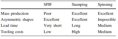
The main advantage of SPIF over other AISF techniques is that it uses a single tool and no counter tooling or moulds,which means that it is easily implemented in an existing,commercially available CNC mill. Using a conventional machine tool lowers the cost required to implement such a process,as well as allowing for other features to be machined in place using conventional machine tools and commercial software. In general,SPIF offers shorter lead times and low tooling cost at the expense of higher cycle times than that can be achieved with traditional forming techniques such as stamping,as outlined in Table 1. SPIF is an ideal custom and prototyping process, and the long cycle times mean that it is not well suited to high volume production. SPIF has also been implemented using a robot as the method of moving the tool,for example Meier et al. [7] used two robots in opposition on either side of the sheet being formed. Duflou et al. [8] also implemented a system where the path of the forming tool was matched on the opposing side by a laser following the same track,heating the sheet metal as it was being deformed to improve formability and reduce spring back of difficult-to-form materials.
Before any useful components can be formed with SPIF,it is necessary to determine the formability limits of the materials of interest. The maximum formability in SPIF is often expressed in terms of the maximum wall angle,Φmax, that can be formed in a single pass [5]. The maximum wall angle increases as a result of thinning in the walls of the sheet during forming. Figure 2 shows how the draw angle changes as the tool moves down.
 |
| Fig. 2Simulations and formed part for a vehicle front light |
SPIF is commonly modeled as a process that induces no displacement of the material radically along the formed edge. Through-wall thickness can be estimated as a function of the wall angle Φ. The wall thickness is loosely approximated using the cosine law,shown in Fig. 3,tf= ticosΦ [9, 10]. Exact measurements will show a slight taper in sheet thickness and a small radial displacement component [11]. As the wall thins while forming,there is a maximum wall angle Φmax which can be formed in practice in a single pass. The wall angle,Φmax; is a useful design criterion as it can be measured directly and applied when designing parts for manufacture with SPIF. Φmax is a useful design criterion in describing which shapes can be formed. Usually,tests are performed on a variety of samples to determine the maximum wall angles that are achievable. These maximum wall angles are then available as a design guide. A set of maximum angles for different materials can be found in Ref. [5]. While Φmax is dominated by material properties,it is worth noting that forming conditions can have an effect as well. Wall angle shown by Ham and Jeswiet [12] was affected by material thickness,tool diameter,and an interaction between material thickness and tool size. To assess material formability,samples of the material are formed using a variable wall angle conical frustum (VWACF) test. A variation of this was proposed in Ref. [5] (see Fig. 4),and later the VWACF test shape with a linearly increasing wall angle was proposed by Hussain and Gao [13]. Parts are formed until fracture occurs within the wall,and based on the final position of the tool at the point of fracture the wall angle at that height can be determined. The VWACF test shape is shown in Fig. 4. For each material,the factors of interest usually are sheet thickness,ti,the step size,z,and the tool diameter,Do. Tool diameters commonly range from 6 mm to 25 mm. Figure 5 shows examples of tool shapes [3, 5, 13, 14, 15]. The stepdown, z,is important because it has a very large impact on cycle time for a given part. The larger isDz,the faster is production. Dz also has a large effect upon surface roughness and the orange peel [16],which can lead to the opposing side of the metal sheet with particular step sizes [17]. Hamilton and Jeswiet [18] developed a relationship for finding equivalent surface roughness in terms of average roughness,Ra,i.e.,10- point average roughness Rz. The tool diameter,d,has been shown to have the largest impact on Φmax and surface roughness [5],aside from the material properties.


 |
| Fig. 5Examples of tool shapes |
Since the milestone paper on SPIF in 2005 [5],considerable experience has been gained. Based on the experience of the last decade,a simple guide was introduced with the aim to have an introductory set of instructions to enable designers to fully exploit the advantages of SPIF [19]. The process of taking a design to a final produced shape can be broken down to the following three main areas: model generation,toolpath generation,and production.
Creating a design that is suitable for production using SPIF begins with the following general rules:
(i) Check the part that can fit in the blank holder working volume.
(ii) Design the part such that it consists of one concave surface,bounded by a flange of undeformed sheet. This allows the part to be clamped.
(iii) Walls must be drafted at some angle Φ from the sheet plane (see Fig. 3). Forming is the easiest and fastest when wall angles are kept below Φmaxfor the material. Steeper walls can be formed using multi-pass methods but at greatly increased cost and time. Hagan and Jeswiet [20] alluded to these formal steps without stating them.
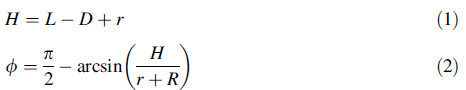
4 Formability tests 4.1 Determining wall angleDuring forming a VWACF test,the wall angle at a given point can be determined from the final depth of the tool geometrically. In Fig. 6,the tool is represented as a circle of radius r,contacting the wall of the test shape of radius R. The position of the tip of the tool from the top of the part is recorded as D. The vertical height of the tool above the bottom of the test shape is then determined by adding the overall depth of the part L with the tool radius,as shown in Eqs. (1) and (2). The estimated error of the wall angle is a function of the stepdown using this method,and can be calculated using Eq. (3).
 |
| Fig. 6Geometry used to determine the wall angle Φ for a given tool position [21] |
To determine the effect of tool shape on formability in SPIF,a series of experiments were conducted varying the tool and stepdown. Experiments were conducted measuring formability based on a factorial experimental design with four corner points,and for each test the test shape was formed from a flat sheet until fracture occurred within the wall. At the point of fracture,the test was stopped and the vertical position of the tool was recorded. When fracture occurred it was always highly audible. The wall angle was then determined following the method outlined previously. After forming,measurements of surface roughness were taken to allow comparison of post-forming surface finish with the pre-formed surface. To ensure consistency of the results,the tests were performed in random order. The tools were cleaned and polished between tests. A special tool was mounted in the work cell for this purpose.
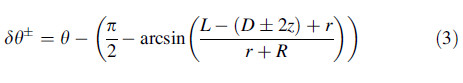
The forming experiments were conducted on 5052-H32 aluminum sheet with an initial thickness of ti = 1.02 mm. Values used for these experiments are R = 50 mm,and L = 39.3 mm. Figures 7 and 8 shows the results with a general trend of decreasing wall angle with increasing tool diameter and stepdown. The treatments used are shown in Table 2,with combinations of tool diameter,d,and step size,z. After forming,measurements of surface roughness are taken to allow comparison of post-forming surface finish.
 |
| Fig. 7Maximum wall angle, Φmax, for aluminum 5052-H32 (error bars represent variability from three replicates of each experimental condition) |
 |
| Fig. 8Maximum wall angle, Φmax, corresponding to step size and tool diameter, for 5052-H32 aluminum sheet with an initial thickness of 1.02 mm |
Additional tests have been carried out for steel materials, as shown in Fig. 9.
 |
| Fig. 9Results for tests on steels |
As observed previously,tool selection has a large impact on overall part quality. In general,smaller tools tend to allow for higher wall angles but with rougher surfaces. The two notable exceptions to this trend are with the thicker aluminum samples and stainless steel samples. When forming 1.99 mm thick aluminum,considerable spallingwas observed when using a 6.35 mm diameter tool. This effect was more significant when forming 2.49 mm aluminum using a 6.35 mm diameter tool. When severe spalling occurred the part failed prematurely with an extremely poor surface finish. For this reason a new tool was developed and used on this material using a flat-end with the dimensions,as shown in Fig. 5. The flat-ended tool produced a maximum wall angle of Φmax=72.9o. While this was similar to the wall angles formed using other tools,the main difference was in the elimination of almost all spalling from the sheet. When forming the stainless steel samples,similar poor surface roughness and low wall angles were observed. It was likely that this poor result was due to the high yield strength of the stainless steel,as degradation of spherical tools was observed after forming. The tool tips became flattened,producing unfavourable tribological conditions. The implementation of the flat-ended tool allowed for both the best formability and the best surface finish.
5 Forming models 5.1 Closed-form modelNumerical simulations have been conducted for SPIF to gain a better understanding of the process and its limits [22, 23, 24, 25, 26, 27]. The first detailed model developed to study the mechanics of deformation in SPIF was a closed-form,nonfinite- element (non-FE) model of single point incremental forming by Martins et al. [28]. This model provided explanations for the deep drawing that was possible with SPIF when comparing it to standard deformation processes. The model [28] is based on membrane analysis with bidirectional in-plane contact friction and is focused on the extreme modes of deformation that are likely to be found in single point incremental forming processes: necking. Formability is limited by fracture without prior necking and is along the inclined cross sectional shape of the crack to the sheet surface. The reason for deeper draws with SPIF is the suppression of localized necking and is due to the inability of necks to grow. ‘‘If a neck was to form at the small plastic deformation zone in contact with the incremental forming tool,it would have to grow around the circumferential bend path that surrounds the tool. This is difficult and creates problems of neck development. Even if the conditions for localized necking could be met at the small plastic deformation zone in contact with the tool, growth would be inhibited by the surrounding material which experiences considerably lower stresses’’,this was said by Martins [28]. The rate of accumulated damage in stamping grows faster than in SPIF. This explains why the forming limits of SPIF are higher than those in conventional stamping processes. Because the triaxiality ratio of metal forming (the ratio of hydrostatic pressure (mean stress) to the equivalent von Mises stress) in conventional stamping is higher than that of SPIF,it can be concluded that the rate of accumulated damage in stamping grows faster than in SPIF. The triaxiality ratio can explain that the onset of cracks during incremental forming of pyramid shape components is preferentially located at its corners. The influence of the radius of the forming tool on the triaxiality ratio is opposite to that of the sheet metal thickness, hence formability is expected to increase when the radius of the forming tool decreases to sizes within reason— a minimum 5 mm tool diameter is a good rule of thumb. This was also observed in Ref. [5].
5.2 Finite element formulationsBecause the diameter of the forming tool used in the SPIF is very small compared to the size of the blank resulting in a small area of contact between the tool and blank,a very fine mesh is required for a SPIF simulation further increasing the computation time. Numerical simulation of SPIF is therefore a complex and time consuming process. A compromise is usually required between accuracy and CPU efficiency,which is influenced by analysis type, finite element formulation,material law,mesh size and the contact algorithm employed [24]. A recent survey found that the problem in creating an adequate finite element model was to maintain a balance between computational efficiency and accuracy. The review only covered the effects on the simulation due to analysis type and elements. No detailed work has been found on the effect of material law and contact algorithm,which is critical to SPIF. In one case study by Ambrogio et al. [25] an explicit model was developed to reduce the calculation time of an implicit analysis from several days to abouttwo hours with good agreement between the predicted results.
Explicit methods offer reasonable accuracy considering the computation time needed for the implicit method. However,they are unable to predict the springback which occurs due to the dieless nature of the process. Even though the implicit method provides with better prediction of the geometry and thickness,it is a time consuming process. Various techniques like adaptive remeshing are able to provide better results by reducing the time required for computation. Shells are central to finite element models. Conventional shells have been used successfully for simulation of the SPIF process. They are suitable to model thin sheet metal when only the thickness and force predictions are essential. However,they are unable to predict the through thickness parameters such as through thickness shear and flow of the material. In order to predict the through thickness gradients,time consuming solids can be replaced by the solid shell elements. Solid-shell elements can have unlimited integration points defined in the thickness direction for better prediction of through thickness gradients in comparatively less computation time. This statement can be supported by the constant enhancement of the solid-shell element and development of reduced enhanced solid-shell (RESS) element. Along with the enhanced assumed strain (EAS) and selective reduced integration,the RESS has been integrated with assumed natural strain (ANS). This gives the element enough flexibility to avoid any kinds of locking that might occur in the linear element. However, the underestimation of force is a major setback of this element.
5.3 Multi-pass single point incremental formingMulti-pass forming methods allow parts to be formed with wall angles that greatly exceed the Φmax limit for a single pass. Multi-pass forming essentially allows wall angles to be formed above Φmax by defeating the cosine law of wall thinning. This is done by changing the distribution of material within the part wall by adding strain to the otherwise largely unstrained section at the bottom of the part. This reduces the strain required within the steeper sections thereby allowing part shapes with steeper angles to be formed. The most critical step in developing multi-pass forming programs is to develop intermediate model shapes. Each forming step must have a corresponding 3D CAD model,and the change in shape between models dictates the strain distribution. Currently there is no simple,reliable method for developing intermediate models for any given part shape,however this is an area of ongoing research. Young and Jeswiet [6],who coined the term SPIF,first reported the work on multi-pass SPIF 4,and then related work was later reported by Xu et al. [26]. It is now commonly used. A major area of ongoing research in this field is the development of methods for quickly predicting the strain in multi-pass forming operations,which can then be used to develop intelligent forming strategies [27].
6 Materials,forces and lubricationNon-metals have been tried with SPIF,with one example being plastic [28]. Plastic exhibits a different failure mode than conventional metal,as it twists globally rather than failing at a single point. Developing new strategies to prevent this is an area of ongoing research [29, 30]. In recent work,two industrial use materials having coatings were tested: galvanized steel to prevent corrosion,and a galvanealed satin coat to allow a paintable finish. While the galvanized coating was removed by all hemispherical tools used with large pieces being spalled off by the tool,it remained intact on the inner surface of the samples when using the 15.8 mm hemispherical tool,suggesting that large flat tools may produce lower contact stresses than their hemispherical counterparts. The galvanealed coating was removed by the tool in all cases with the coating on the exterior of the part as intact. Qualitatively,the coating does not appear to be affected by the combination of tool diameter or stepdown. The galvanized coating spalled easily while forming,with larger pieces coming off with the use of larger tools. More exotic materials such as titanium and magnesium have been tried,with partial success [7, 31, 32, 33, 34, 35].
Numerical models [33] need experimental verification. Duflou et al. [36] established a set of equations which estimate the forces in SPIF. For verification of numerical models,forces have been measured in SPIF for several cases [36, 37, 38, 39, 40]. In a study on energy consumption in SPIF, while testing the effects of lubricants,Adams and Jeswiet [41] found the specific lubricant appears to have little effect on the surface quality or formability. In the case of lubrication, the important factor is instead the presence of a lubricant and the ability of a lubricant to stay in the path of the tool. A friction coefficient of μ=0:22 was used. Camino et al. [42] also found a moderate change in friction forces does not significantly influence formability. In an extensive study,Azevedo et al. [43] found lubricants influence the final surface quality of the parts made with SPIF. They found the use of a suitable lubricant may significantly improve the surface finish quality,reduce forming forces and prevent tool wear. Obviously,the surface condition of the tool plays an important role in the final surface condition. The effect of environmentally friendly lubricants has also been observed in SPIF [44],but more work remains to be done.
7 Production and industrial examplesOne drawback to implement SPIF in large scale volume
production is the time in manufacturing a part with SPIF.
This still remains a problem for large volume production
runs and is an area ripe for research. Initial steps toward
increasing production speeds were made by Hamilton and
Jeswiet [18],with production speeds up to 5 080-8 890 mm/min at the tool/sheet contact interface. A spindle
speed/feed rate factor  and a shape factor defined as
forming angle/tool diameter
and a shape factor defined as
forming angle/tool diameter  were developed; k = 2.54
when using metric units and 1 when using imperial. The
extent of orange peel formation was shown to be a function
of the shape factor,
were developed; k = 2.54
when using metric units and 1 when using imperial. The
extent of orange peel formation was shown to be a function
of the shape factor, ,a ratio between the forming angle
and step size. Ambrogio et al. [34] increased speeds substantially
to 500 m/s with a MoS2 lubricant for Ti6Al4V.
,a ratio between the forming angle
and step size. Ambrogio et al. [34] increased speeds substantially
to 500 m/s with a MoS2 lubricant for Ti6Al4V.
A manufacturer needed to test a range of aerodynamically shaped cone components. The cones could easily have been made by spinning,but for one problem,the prototype parts,once made had to be held in place in a special holder. SPIF was the perfect candidate for making series of parts for experimentation by the company. Figure 10 shows the cones.
 |
| Fig. 10Aerodynamic cones |
The manufacturer also needed a redesigned pressure sensor casing,called an airflow management system (AFMS),to make mounting of internal electronics more stable and easy to assemble. The current design consists of a can,spun from galvanized steel,into which the pressuretransducer chips are installed. The top and bottom faces are then mounted and sealed to the can. Pressure taps are installed to the bottom face,and the display chip is mounted to the top face. Electronic parts are hung inside in a haphazard manner,with electronic parts able to touch each other when the unit is moved. These are then installed in a multi-million large-scale HVAC system. The redesign and SPIF manufactured casing are shown in Fig. 11.
 |
| Fig. 11Three stages of the AFMS redesign with final prototype II |
To improve formability in SPIF,particularly with exotic materials,many methods have been presented that focus on heating the sheet metal using electric current through the tool [30, 44, 45, 46]. These have had mixed success and are still at the early stages of experimentation. Little work has been carried out,however,to determine the direct effect of electric current as opposed to simple resistive heating on formability. Electro-SPIF,is based upon work in Refs. [45, 46] where it was shown that pulsed high electric currents could increase the plasticity of hard-to-form metals such as titanium and magnesium at room temperatures. The process does not rely completely on resistive heating. Preliminary experiments have been started on using a SPIF system that uses a high current (up to 900 A) when forming titanium sheet [30]. Using good estimates for contact area [21],one obtains the current density needed for electroassisted forming. These experiments have only been partially successful and much research work remains to be done before this method can be used to form exotic sheet metals. Work on faster production speeds,such as that in Refs. [18, 34],need to be extended to actual production runs before industry invests further in SPIF. Examples such as in Fig. 11 and in Ref. [3] are needed to show that SPIF is a viable prototype and production technique.
Geometrical errors are a problem with this SPIF as discussed in Ref. [47]. However,for products such as the AFMS shown in Fig. 11,proper design and understanding of the SPIF process can overcome this.
Acknowledgements The authors thank NSERC and Auto 21 for their support.| 1. | Leszak, E. Patent US3342051A1, 1967-09-19. Apparatus and process for incremental dieless forming |
| 2. | Kitazawa K, Wakabayashi A, Murata K, Yaejima K (1996) Metal flow phenomena in computerized numerically controlled incremental stretch-expanding of aluminum sheets. J Jpn Inst Light Metals 46:65-70 |
| 3. | Jeswiet J (2000) Rapid proto-typing with incremental single point forming. J CAD/CAM Comput Graph 15(2-3-4):177-183, Dec. 2000; special edition on rapid production development |
| 4. | Jeswiet V (2001) Incremental single point forming. Trans N Am Manuf Res Inst XXIX:75-79 |
| 5. | Jeswiet J, Micari F, Hirt G, Bramley A, Duflou J, Allwood J (2005) Asymmetric single point incremental forming of sheet metal. Ann CIRP 54(2):623-650 |
| 6. | Young D, Jeswiet J (2004) Wall thickness variations in single point incremental forming. IMECHE Part B 218(B11):1453-1459 |
| 7. | Meier H, Buff B, Laurischkat R, Smukala V (2009) Increasing the part accuracy in dieless robot-based incremental sheet metal forming. CIRP Ann Manuf Technol 58:233-238 |
| 8. | Duflou JR, Callebaut B, Verbert J, De Baerdemaeker H (2007) Laser assisted incremental forming: formability and accuracy improvement. Ann CIRP 56(1):273-276 |
| 9. | Kegg RL (1961) A new test method for determination of spinnability of metals. Trans ASME, J Eng Ind 83:119-124 |
| 10. | Kalpakcioglu S (1961) On the mechanics of shear spinning. Trans ASME Ser B 83:125-130 |
| 11. | Bambach M (2010) A geometrical model of the kinematics of incremental sheet forming for the prediction of membrane strains and sheet thickness. J Mater Process Technol 210(12):1562-1573 |
| 12. | Ham M, Jeswiet J (2006) Single point incremental forming and the forming criteria for AA3003. Ann CIRP 55(1):241-244 |
| 13. | Hussain G, Gao L (2007) A novel method to test the thinning limits of sheet metals in negative incremental forming. Int J Mach Tools Manuf 47:419-435 |
| 14. | Cawley B, Adams D, Jeswiet J (2012) Examining tool shapes in single point incremental forming. Proc NAMRI/SME 26:201-206 |
| 15. | Adams D, Jeswiet, J (2015) Tool shapes in single point incremental forming: an experimental study. IMECHE J Eng Manuf (in press) |
| 16. | Carrino L, Giuliano G, Strano M (2006) The effect of the punch radius in dieless incremental forming. 2nd I*PROMS virtual international conference on intelligent production machines and systems pp. 204-209 |
| 17. | Hamilton K, Jeswiet J (2010) Visual categorization and quantification of the orange peel effect in single point incremental forming. Trans NAMRI/SME 38:679-686 |
| 18. | Hamilton K, Jeswiet J (2010) Single point incremental forming at high feed rates and rotational speeds: surface and structural consequences. Ann CIRP 59(1):311-314 |
| 19. | Adams D, Jeswiet J (2015) Design rules and applications of single point incremental forming. IMECHE J Eng Manuf 229(5):754-760 |
| 20. | Hagan E, Jeswiet J (2003) A review of conventional and modern single point sheet metal forming methods. J Eng Manuf 217(B2):213-225. Awarded the I MECH E Joseph Whitworth Prize for best paper of 2003 in the IMECHE Journal of Engineering Manufacture |
| 21. | Adams D, Jeswiet J (2014) A new model for contact geometry in single point incremental forming. IMECHE J Eng Manuf 39:125-136 |
| 22. | Hussain G, Lin G, Hayat N, Iqbal A (2010) On the effect of curvature radius on the spifability. Adv Mater Res 129-131:1222-1227 |
| 23. | Martins PAF, Bay N, Skjoedt M, Silva MB (2008) Theory of single point incremental forming. CIRP Ann Manuf Technol 57:247-252 |
| 24. | Sena JIV, Alves de Sousa RJ, Valente RAF (2011) On the use of EAS solid-shell formulations in the numerical simulation of incremental forming processes. Eng Comput 28(3):287-313 |
| 25. | Ambrogio G, Filice L, Gagliardi F, Micari F (2005) Three-dimensional FE simulation of single point incremental forming: experimental evidences and process design improving. VIII international conference on computational plasticity COMPLAS VIII |
| 26. | Xu D, Malhotra R, Reddy NV, Chen J, Cao J (2002) Analytical prediction of stepped feature generation in multi-pass single point incremental forming. J Manuf Processes 14:487-494 |
| 27. | Malhotra R, Bhattacharya A, Kumar A, Reddy NV, Cao J (2011) A new methodology for multi-pass single point incremental forming with mixed toolpaths. CIRP Ann Manuf Technol 60(1):323-326 |
| 28. | Martins PAF, Kwiatkowski L, Franzen V, Tekkaya AE, Kleiner M (2009) Single point incremental forming of polymers. CIRP Ann Manuf Technol 58:229-232 |
| 29. | Duflou J, Vanhove H, Verbert J, Gu J, Vasilakos I, Eyckens P (2010) Twist revisited: twist phenomena in single point incremental forming. CIRP Ann Manuf Technol 59(1):307-310 |
| 30. | Adams D, Jeswiet J (2014) Single point incremental forming of 6061-T6 using electrically assisted forming methods. IMECHE J Eng Manuf 228(7):757-764 |
| 31. | Ambrogio G, Filice L, Manco GL (2008) Warm incremental forming of magnesium alloy AZ31. CIRP Ann Manuf Technol 57:257-260 |
| 32. | Hino Ryutaro, Kawabata Keita, Yoshida Fusahito (2014) Incremental forming with local heating by laser irradiation for magnesium alloy sheet. Proc Eng 81:2330-2335 |
| 33. | Henrad C, Bouffioux C, Eykens P, Sol H, Duflou JR, van Houte P, van Bael A, Duchene L, Habraken A (2011) Forming forces in single point incremental forming: prediction by finite element simulations, validation and sensitivity. Comput Mech 47:573-590 |
| 34. | Ambrogio G, Gagliardi F, Bruschi S, Filice L (2013) On the highspeed single point incremental forming of titanium alloys. CIRP Ann Manuf Technol 62:243-246 |
| 35. | Fan G, Sun F, Meng X, Gao L, Tong G (2010) Incremental forming of Ti6Al4 V titanium sheet. Int J Adv Manuf Technol 49:941-947 |
| 36. | Duflou J, Tunçkol Y, Szekeres A, Vanherck P (2007) Experimental study on force measurements for single point incremental forming. J Mater Process Technol 189(1-3):65-72 |
| 37. | Jeswiet J, Szekeres A (2005) Forces in single point incremental forming. Trans N Am Manuf Res Inst XXXIII:399-404 |
| 38. | Jeswiet J, Szekeres A, Ham M (2007) Force measurement with a spindle mounted force sensor. Trans NAMRI/SME 35(2007):255-262 |
| 39. | Szekeres A, Ham M, Jeswiet J (2007) Force measurement in pyramid shaped parts with a spindle mounted forcesensor. J Key Eng Mater 344:551-558 |
| 40. | Jeswiet J, Duflou JR, Szekeres A (2005) Forces in single point and two point incremental forming. J Adv Mater Res 6-8:449-456 |
| 41. | Adams DW, Jeswiet J (2012) Energy consumption in single point incremental forming. Proc NAMRI/NAMRC 40:738-742 |
| 42. | Camino L, Di Meo N, Sorrentino L, Strano M. The influence of friction in the negative dieless incremental forming process. The 9th international ESAFORM conference on material forming |
| 43. | Azevedo NG, Farias JS, Bastos RP, Teixeira P, Davim JP, de Sousa RJA (2015) Lubrication aspects during single point incremental forming for steel and aluminum materials. Int J Precis Eng Manuf 16(3):589-595 |
| 44. | Shi X, Gao L, Khalatbari H, Xu Y, Wang H, Jin L (2013) Electric hot incremental forming of low carbon steel sheet: accuracy improvement. Int J Adv Manuf Technol 68:241-247 |
| 45. | Roth JT, Loker I, Mauck D, Warner M, Golovaschenko SF, Krause AL (2008) Enhanced formability of 5754 Al sheet metal using electric pulsing. Trans NAMRI/SME 36:405-412 |
| 46. | Collins TJ, Roth JT (2010) Deep drawing of 5052 aluminium strips using electrically-assisted manufacturing. Trans NAMRI/SME 38:8 |
| 47. | Micari F, Ambrogio G, Filice L (2007) Shape and dimensional accuracy in Single Point Incremental Forming: State of the art and future trends. J Mate Process Technol 191(1-3):390-395 |