 2015, Vol. 3
The article information
- A. Mohammadhosseini, S. H. Masood, D. Fraser, M. Jahedi
- Dynamic compressive behaviour of Ti-6Al-4V alloy processed by electron beam melting under high strain rate loading
- Advances in Manufacturing, 2015, 3(3): 232-243
- http://dx.doi.org/10.1007/s40436-015-0119-0
-
Article history
- Received: 2014-06-16
- Accepted: 2015-08-14
- Published online: 2015-09-11


2 Commonwealth Scientific and Industrial Research Organisation, Clayton, Melbourne 3168, Australia
Electron beam melting (EBM) is becoming a viable additive manufacturing technology forrapid fabrication of metallic parts directly from 3D CAD model for various engineering and biomedical applications [1]. Compared to selective laser sintering (SLS),EBM is also a powder-bed type process,but it uses an electron beam as its power source in a vacuum chamber to selectively melt metal powder. Consequently,EBM offers a higher build rate due to high energy density and scanning speeds,and it produces full dense parts with better mechanical properties than traditional cast parts. In principle,any metal powdercanbeusedaslongasitconformstotheprocessin terms of particle size and shape. However,the main metals used in current EBM process are titanium alloy (Ti-6Al-4V) and CoCr alloy. Other potential materials which can be developed for EBM with further research and development efforts include aluminium and its alloys,steels,superalloys,inter-metallics and refractory metals and alloys [2]. Titanium alloy (Ti-6Al-4V) offers a combination of high strength,light weight,low heat conductivity and corrosion resistance,which has made it a world standard alloy for aerospace applications. Some of the many applications where this alloy has been used include aircraft turbine engine components,aircraft structural components,aerospace fasteners,high-performance automotive parts, bio-medical devices and implants,and sports equipments. Another EBM material,Co-Cr alloy,has excellent mechanical properties,wear resistance and biocompatibility.
Because of the excellent properties of Ti-6Al-4V and CoCr alloys,the EBM process is finding wider applications for highly valued customised components in aerospace, automotive and biomedical industries. As EBM made parts are expected to be increasingly used in such applications,it is necessary to understand how EBMmanufactured parts behave under various mechanical loading conditions and how the properties of such materials are affected by the EBM process for specific applications. There have been several studies on the mechanical behaviour of metallic parts fabricated through EBM process. Facchini et al. [3] investigated the tensile properties and micro-hardness of EBM parts. Koike et al. [4] studied the modulus of elasticity,grindability and corrosion resistance of EBM made Ti-6Al-4V samples. Murr et al. [5] compared the mechanical properties of Ti-6Al-4V made by EBM and wrought processes for biomedical application. In another study,Murr et al. [6] compared the microstructures and mechanical properties of parts made by EBM and selective laser melting (SLM) with conventional wrought and cast products of Ti-6Al-4V. Li et al. [7] investigated the static compressive strength and Young’s modulus of porous parts for biomedical application. Harrysson et al. [8] investigated the process of direct manufacturing of titanium implants with tailored materials and mechanical properties using EBM. Parthasarathy et al. [9] studied compressive stiffness and compressive strength of porous titanium parts. Murr et al. [10] discussed the Young’s modulus of open cellular Ti-6Al-4V fabricated by EBM process. Parthasarathy et al. [11]proposed design strategy using finite element analysis (FEA) for manufacturing implants with better mechanical properties. Heinl et al. [12] compared the compressive strength and elastic modulus of the EBM made porous parts with those of human bone. Mohammadhosseini et al. [13, 14, 15] studied the tensile, fatigue,and static compressive behaviour of EBM made Ti-6Al-4V parts and also the effects of heat treatment on the mechanical properties and microstructure of the same material.
The dynamic behaviour of Ti-6Al-4V parts made by conventional manufacturing processes has been studied by several researchers [16, 17, 18],but a comprehensive study on the dynamic behaviour of titanium alloys processed by additive manufacturing processes has received little attention. Biswas et al. [19] studied the deformation and fracture behaviour of Ti-6Al-4V alloy processed by laser engineered net shaping (LENS) additive manufacturing process. They studied the effects of porosity of the parts created by LENS process under quasi-static and dynamic loading conditions at various strain rates. In engineering applications,where EBM made components are subjected to impact and dynamic loading conditions,it is necessary to understand the material response of EBM made parts for effective design and manufacturing requirements. Moreover,layer by layer building process of metal powder in the EBM process itself influences the microstructure and hence the mechanical behaviour of the built parts. The EBM fabricated parts are functional parts that can be used for different applications involving low strain rate loadings such as in biomedical implants,in high strain rate loadings,or in aircraft structural components. There appears to be a lack of research efforts to understand the mechanical behaviour of EBM fabricated parts especially titanium alloy subjected to low and high strain rate dynamic loading conditions.
This paper presents an experimental investigation on the static and dynamic behaviour of Ti-6Al-4V alloy processed by EBM additive manufacturing process when the parts are subjected to high strain rate compressive loading using the split Hopkinson pressure bar (SHPB) test system. The stress-strain behaviour,microhardness and microstructure behaviour of EBM made Ti-6Al-4V specimens under high strain rate and static compression loading conditions are described. A numerical study of the SHPB system for dynamic behaviour of EBM made Ti specimen is also presented to compare and verify the experimental results. 2 Experimental 2.1 EBM
EBM,developed by Arcam in Sweden,is a relatively novel powder-based additive manufacturing process. The electron beam is used as a heat source to melt the powder. Typically,the electron gun operates at 60 kV to develop an energy density in the focused beam in excess of 100 kW/ cm-2 . Figure 1 shows the schematic diagram of the EBM process.
 |
| Fig. 1 Schematic of EBM process |
The electron beam is developed by passing a current through a tungsten filament and used as a heat source to melt the powder. Two magnetic coils are used to control the electron beam. One focuses the beam to the required diameter,while the other one deflects the focused beam to the desired point on the build table. The 4 kW electron beam gun preheats the build platform which is made of stainless steel. For preheating,a relatively low beam current and relatively high scan speed are used. Then,a 50lm layer of metal powder is spread over the base plate. There are two main purposes for preheating: one is to decrease the thermal gradient between melted layer and the rest of the part and secondly; the other is to sinter the metal powder to keep it in place during subsequent melting at higher beam powers. Both the preheating and melting are controlled by process setting themes. Beam power is higher in the preheating theme. The offset focus is increased so that the beam is defocused and it spreads the beam energy in the preheating. The preheating beam rapidly scans lines which are offset to each other over the build area and it goes through a number of repetitions in order to raise the temperature to 720℃ without over sintering. However,the melting step is controlled by a separate theme that is characterised by a lower offset focus resulting in a focused beam,which operates at reduced scan speeds and currents relative to the preheating to achieve melting. Firstly,the outline of the part is melted, which is called contouring. Then the part is filled in by hatching. The beam current and scanning speed for contouring are*4 mA and 100 mm/s-300 mm/s,respectively. And for the hatching,they are*6-15 mA and 100-4 000 mm/s,respectively. The offset focus is optimised for this machine at 10 mA. After melting the layer of powder,the build platform is lowered by 50lm,which is equal to the thickness of one layer. In the next step,a new layer of metal powder is spread and the process is repeated until the part is complete. The whole manufacturing process is run in a vacuum chamber,especially suitable for materials with a high affinity to oxygen such as titanium and its alloys. After all layers have been melted,the manufactured parts are cooled down in the process chamber. Upon completion of the building process,the part is removed from the build chamber and placed in the powder recovery system (PRS). Pressurized air with Ti-6Al-4V particles is used in the PRS in order to perform blasting to remove any powder clinging to the part surface. One of the main advantages of this technology is that the unused powder particles are not affected by the heat source and can be recycled for further fabrication.
In EBM process,particle size distribution of powder material is very important for part fabrication. The particle size distribution was measured using Malvern Mastersizer X machine. Figure 2 shows the particle size distribution of powder as measured using laser diffraction technique. As shown in Fig. 2,the powder had a median particle diameter of D(v,0.5) of 67lm,which means that 50% of the sample is smaller and 50% is larger than 67 lm. The particle size D(v,0.1) of 50lm means 10% of the sample is below this size,and D(v,0.9) of 89lm means that 90% of the sample is below this size. A very fine distribution range of powder was observed which is suitable for EBM process.
 |
| Fig. 2 Volume distribution of powder |
It is commonly understood that the mechanical properties of the parts are dependent of their chemical composition. The nominal chemical composition of powder was measured by X-ray fluorescence (XRF) and interstitial content by LECO - TCH600 system before the first use and also compared with recycled powder after 90 builds,as shown in Table 1.

Comparison of chemical composition of original and recycled powder with the ASTM standard requirements (see Table 1) shows that while original powder is suitable for manufacturing surgical implants,the recycled powder is not suitable for such implants. Because the oxygen content in recycled powder exceeds the standard amount of oxygen requirement. However,recycled powder can be used for manufacturing other engineering components. 2.2 Dynamic compression test
The SHPB is a common method for investigating the mechanical behaviour of metals subjected to high strain rates. This equipment has a capability to test materials at strain rates from 102 /s to around 104 /s,which is sufficient to simulate high speed crashes and high strain rate impacts [19]. In this experiment a high strain rate of over 1×10³ /s was applied on EBM made samples using a SHPB apparatus in order to study how the EBM made parts behaved under high strain rate load in compression. Figure 3 shows the setup of the SHPB used in this investigation.
 |
| Fig. 3 Schematic of SHPB |
The setup consists of a striker bar 300 mm long,and
incident and transmission bars each 1 200 mm long and all
14.5 mm diameter,which are made of maraging steel 350
(AISI 18 Ni). Cylindrical samples were fabricated on the
EBM machine,and then machined into two sizes of 6 mm
diameter,4 mm length and 6 mm diameter,5 mm length in
order to give different aspect ratios (height/diameter). The
aspect ratios of 0.66 and 0.83 were used in this study to
facilitate dynamic stress equilibrium. At least seven specimens from each type were tested to get average results. All
tests were performed at ambient temperature. In order to
reduce the friction effect,the contacting surfaces of the
specimens and the bars were lubricated. The impact
velocities of 25 m/s and 30 m/s were applied on the
moveable strike bar to hit the incident bar coaxially. The
test specimens were sandwiched coaxially between incident and transmission bars. Generally,higher impact
velocity will generate higher strain rates. When the striker
bar impacts the incident bar,an elastic compressive stress
pulse is generated and propagates through the incident bar
toward the other end of the system. It is worthwhile to note
that the length of the striker bar determines the duration of
the stress pulse. When the stress pulse reaches the specimen section,part of the pulse is reflected back to the
incident bar as a tensile pulse and the rest is transmitted to
the transmission bar as a compressive pulse. The magnitude of the stress pulse is adjusted so that the incident and
transmission bars remain elastic whereas the specimen
deforms plastically. The stress strain relation for the sample
can be derived using the strain gage measurements,which
are mounted at a certain distance on the incident and
transmitted bars to record the amplitudes of the stress
pulses or the corresponding elastic strains. The signals
from the strain gauges are amplified and recorded by high
speed digital oscilloscope. The calculations of engineering
stress (δ),engineering strain (ε) and engineering strain rate
( ) for a specimen as a function of time are given by the
following equations
) for a specimen as a function of time are given by the
following equations
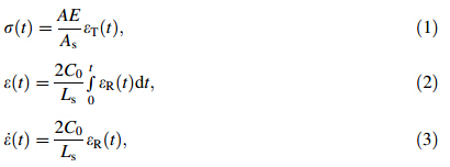
It can be seen from Eqs. (1)-(3) that the strain and strain rate are proportional to the reflected wave while the stress is proportional to the transmitted wave. Figure 4 shows the magnitudes of incident,reflected and transmission pulses obtained from the strain gages.
 |
| Fig. 4 Strain gauge output in SHPB system for Ti-6Al-4V specimen |
The stress,strain and strain rate can be calculated at the bar-specimen interface,the input bar-specimen interface or the specimen-output bar interface. Due to the fact that strain gages were mounted away from these interfaces,the signals will be transformed,corrected and reconstructed back to the bar-specimen interfaces following the characteristics of the longitudinal wave propagating in the bar, which is naturally dispersed.
It is noted that the accuracy of the signals measured by the strain gauges is affected by wave dispersion and noise presence. If the dispersion in the incident bar is significant, then the specimen is subjected to an oscillating component of the load,which can adversely affect the high strain rate property being measured [20]. Therefore,a dispersion correction method was performed in order to minimize the oscillation around the data as displayed in Fig. 4 to get the true specimen behaviour. Figure 5 shows the comparison of incident,transmitted and reflected waves vs. time for the sandwiched specimen. In order to calculate the engineering stress,strain and strain rate in the specimen,the modified reflected and transmitted strain values were used in Eqs. (1)-(3).
 |
| Fig. 5 Comparison of the raw strain gauge data for cylindrical specimen |
A 3D finite element model of SHPB was used to investigate the dynamic deformation behaviour of EBM made samples and verify the experimental results from the SHPB test system. Figure 6 shows the half section of the components of the numerical model of the test system. The numerical simulations were conducted using ANSYS-LS DYNA. In the model,two axes of symmetry were assumed, and the components of SHPB set-up parts were modelled using 2D axisymmetric shell elements.
 |
| Fig. 6 Numerical model of SHPB set-up |
The bars were made of maraging steel 350 and the material properties were assigned to the specific parts in the modelling. The tensile strength,Young’s modulus,density and Poisson’s ratio were taken as 2 310 MPa,190 GPa, 8000 kg/m3 and 0.3,respectively. In order to achieve valid results,the material model of the bars should remain in a linear-elastic state during the experiment [21]. The MAT 001-Elastic was selected as a material model for all the bars including the striker,input,and output bars. The maximum stress generated by an impact of striker bar can be calculated

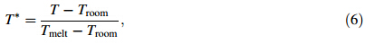
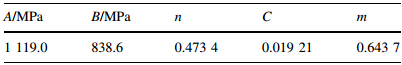
The shell element size of 1.5 mm was used to mesh the parts,and mesh biasing along the bar axis was applied to refine the meshes at the contact interfaces. The stress-strain behaviour of Ti-6Al-4V specimen was modelled using constitutive material model such as the simplified JohnsonCook (MAT098) [22]. The Johnson-Cook model is a viscoplastic model for ductile metals. The advantage of using this model is that the effects of strain rate on material behaviour and fracture can be considered. This model was first published in 1983 and since then it has been commonly used in the literature for modelling the stress-strain behaviour. The Johnson-Cook constitutive constants for titanium alloy are as shown in Table 2 and the flow stress of simplified Johnson-Cook is calculated

 is the dimensionless plastic strain rate; and T*
is the homologous
temperature and can be calculated
is the dimensionless plastic strain rate; and T*
is the homologous
temperature and can be calculated
The sampling rate of simulations was selected to be 1ls and a termination time was selected to be 500ls. Several elements were chosen to measure the strain wave propagation at the location of the strain gauges. The force,stress, and strain values were calculated at several locations and the averages of them were considered.
Figure 7 shows the comparison of imposed strain rate history corresponding to the raw data for the specified dimensions of the two specimens as obtained from SHPB experiments as well as the results from the numerical analysis.
 |
| Fig. 7 Imposed strain rate history corresponding to the raw data for different dimensions |
As mentioned earlier,the strain rate is proportional to wave propagation velocity and the amplitude of reflected wave when equilibrium state is achieved,and can be calculated using Eq. (3). As shown in Fig. 7,the comparison between experimental and numerical simulation results reveals a good correlation for the reflected waves considering the phase fluctuations. A dispersion feature of the propagated wave was considered in numerical simulation. Moreover,since the gauge length of the two specimens was close to each other,both of the samples followed the same trend,and the imposed strain rates on the two samples were almost similar. The result demonstrates the average strain rate of 1 600/s at the maximum stress for the specimens as well as for the numerical model. The stress wave travels into the specimen from the incident bar that loads the specimen. Therefore,the strain rate vs. time graph illustrates the magnitude of deformation which the specimen undergoes in response to the stress wave generated by the impact and the mode of dissipation of impact wave. 2.4 Dynamic and static stress-strain behaviour
For ductile materials (such as Ti-6Al-4V),the true stress and strain values are normally used to represent their mechanical behaviour. The true stress,true strain and true strain rate can be calculated [25]
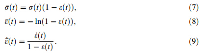
Figure 8 shows the true stress-strain behaviour of the specimens for the specified dimensions of the two specimens as obtained experimentally by SHPB tests as well as the one obtained by numerical modelling of the bar using finite element model.
 |
| Fig. 8 Dynamic true stress-strain curves of Ti-6Al-4V at high strain rate |
As shown in Fig. 8,like all the stress-strain curves of the metallic materials,there are three distinct regions on the true stress-strain curve. In the initial region,because of the impact of the incident bar,rapid increase of stress was observed. This corresponds to the sudden surge of strain rate at 50ls. The stresses created in this region are within the elastic range. In the second region,as the incident pressure wave was transmitted through the specimen,the plateau occurred. This is the zone of energy absorption and it includes plastic deformation. Another considerable factor in this region is that ultimate strength occurred in this zone. In the third region,after termination of impact related effects,the stress dropped to zero. The comparison between experimental and numerical simulation results reveals a good correlation for the results. Figure 8 also shows that the length of the specimen has some effect on the stress-strain behaviour because the striker velocity and specimen length contribute to the nominal strain rate applied to the specimen. For the same impact velocity (25 m/s),the longer specimen (5 mm) will contribute to lower nominal strain rate compared to the shorter specimen. The nominal strain rate in the experiment ranged from 5×10³ /s to 6.25×10³ /s. It is commonly understood that the higher impact velocity will generate higher strain rates. Therefore, the velocity of striker bar was increased to 30 m/s,and consequently the samples were fractured into two halves. The microstructure investigation was then conducted on these samples which will be discussed in a later section. Comparing the dynamic stress strain behaviour of Ti-6Al-4V alloy made by EBM additive process (see Fig. 8)to the dynamic stress strain behaviour of same alloy made by LENS additive process [19],it is noted that the peak stress obtained by EBM specimen is less than that obtained by the LENS specimen for almost similar applied nominal strain rates and almost same length of fully dense specimens.
In addition to the dynamic test,quasi-static compression testing was also carried out for better understanding the behaviour of specimens under low strain rate loading. The experiment was performed on cylindrical shaped EBM built specimens on a numerically controlled hydraulic MTS Criterion Model 43 testing machine. The low strain rate of 10-3 /s was implemented on the specimens. The cylindrical samples with slightly different dimensions were fabricated on EBM,and then machined into sizes of 5 mm diameter,6 mm length and 6 mm diameter,7 mm length in order to have different aspect ratios (height/diameter). Engineering stress-strain curves were derived from the load and deflection data. The true stress-strain curves were derived using a constant volume assumption. The shear failure plane of the deformed specimen is shown in Fig. 9,which shows the specimen split roughly along the 45º shear plane.
 |
| Fig. 9 Shear failure of deformed specimen (6 mm95 mm) during static test |
For ductile materials (such as Ti-6Al-4V),the true stress and strain values would provide better representation of their mechanical behaviour. Figure 10 depicts the true stress-strain curve under quasi-static compression test for specimens with two different sizes. In the first region of the curve,the specimen is elastically compressed up to about the proportional limit. In the second region,the plastic deformation takes place with strain hardening under normal and shear forces,and the maximum compressive strength occurs. After that,the fracture occurred and the stress dropped to zero. And the specimen split roughly along the 45º shear plane. Figure 11confirms the ductile behaviour of Ti-6Al-4V for both dimension sizes.
 |
| Fig. 10 Static true stress-strain curves for different specimen sizes |
Comparing the dynamic stress-strain curves (see Fig. 8) with the static stress strain curves (see Fig. 10) for the EBM made Ti alloy specimens,it is noted that the material becomes more strengthened under dynamic loading conditions. In dynamic curve,the stress of 1 200 MPa soon after impact was achieved at a strain of 2%,while the same stress in quasi-static loading is arrived at a strain of 20%. This behaviour may be caused by the effect of sudden impact of the bar in dynamic test which will bring the material beyond the elastic limit leading to instantaneous strain hardening effect. 2.5 Microstructural observations
Test samples were examined by optical microscope for microstructural analysis of the deformation behaviour after static and dynamic compression tests. In order to characterize the microstructure of the specimen after SHPB and quasi-static compression tests,the specimens were needed to be broken into two halves. During the quasi-static test, the specimens broke into two halves during the experiment, but for the high strain rate SHPB test,the samples did not break into two halves with 25 m/s applied speed on the striker bar. So when the speed was increased to 30 m/s as described earlier,the SHPB specimen broke into two halves (see Fig. 11).
 |
| Fig. 11 Specimens after high strain SHPB test |
One of the halves of the specimen for both quasi-static and dynamic compression tests was again cut into two halves using electrical discharge machining (EDM) wire cutting (see Fig. 12) for scanning electron microscope (SEM) examinations.
 |
| Fig. 12 Specimen after wire cutting using EDM |
The deformation of the specimen has a noticeable effect on the microstructure. After mounting and polishing the specimens,they were etched in order to reveal the details of the microstructure. The metallography samples were etched using a solution of Kroll’s reagent consisting of 97 mL H2O,3 mL HNO3and 1 mL HF. Figure 13 shows the cross-sectional microstructure of the specimen after quasistatic compression test.
As shown in Fig. 13,thea-acicular (hcp phase) structure is surrounded by interfacial β phase and the mixture of α-β has a fine lamellar morphology that can be attributed to the very high solidification rate of the layers. The fracture surface of the specimen was investigated using secondary electron imaging mode in the SEM using Leica S440 equipment. Ultrasonic cleaner was used to clean the samples,in which isopropanol was used as the cleaning solvent.
 |
| Fig. 13 Cross-sectional microstructure after quasi-static compression test |
The low and high magnification of the fracture surface is depicted in Figs.14a,b,respectively. As shown in Fig. 14a, the samples depicted characteristic dimple structures. Generally,Ti-6Al-4V is a ductile material and EBM processed Ti-6Al-4V also remains ductile up to the point of failure.
 |
| Fig. 14 Fracture surface of quasi-static compressive test sample at a low and b high magnification of SEM |
The ductile behaviour of the specimen showing sheared dimples is more visible in Fig. 14b,which correlates with their ductile behaviour in the stress-strain curve. The dimples were found to orient along the maximum shear direction. Both optical microscopy and SEM investigation were conducted on quasi-static specimens. As shown in Figs.13 and14,there was no evidence of existence of adiabatic shear band (ASB) in the specimen.
Figure 15 shows the cross-sectional microstructure of the specimen after high strain rate compression test. Due to high strain rate compression forces,the microstructure has been deformed such that the existing porosity has been affected. However,in the quasi-static compression part,as explained earlier,the microstructure of the specimen remains the same. That is,the X-acicular structure is surrounded by interfacial β phase and the mixture of α-β was observed within elongated priorbgrains. Adiabatic shear band is a thermodynamic phenomenon and it is known to be a precursor to failure. The formation of bands exists at high strain rates, which are characterised by large deformations localised in a narrow band with the width ranging from 5lmto100lm. After large plastic deformations,localised heating may lead to localisation of plastic flow,which is considered as a catastrophic phenomenon since it may lead to fracture by intense localised shearing [26]. Zener and Hollomon [27] named the localized shearing as ‘‘adiabatic shearing’’,which indicates that this phenomenon is happening when thermal softening is larger than strain rate hardening due to conversion of plastic work into heat. The formation of ASBs is not desirable since it causes the material to lose its energy dissipation capacity. It can be found in many applications such as ballistic impact loading,forging,and machine chips [28]. The formation of adiabatic shear band and subsequent failure is prone to occur in titanium and its alloys. Many researchers have paid attention to the investigation of formation of adiabatic shear bands of Ti-6Al-4V such as Peirs et al. [28] and Yin et al. [29]. A closer look in high strain rate dynamic sample (see Fig. 16) shows that adiabatic shear bands were observed on the fracture surface. The surface was viewed perpendicular to the fracture surface. Thus,high strain rate compression leads to localized deformation and a rise in temperature. Consequently,the subsequent cooling leads to existence of adiabatic bands in the microstructure. Considering the micrographs of the samples deformed at high strain rate (see Figs.16,17) taken at two different magnifications,it is noted that,in general,two types of adiabatic shear bands may occur during the deformation of metals under high strain compression test,which are known as ‘‘transformed’’ and ‘‘deformed’’ bands [30, 31]. In general,the transformed bands consist of very fine subgrains while deformed bands consist of highly elongated grains. The deformed bands are usually found at an early stage of shear localization [32, 33, 34],which proposed that because of dynamic recrystallization,the Ti-6Al-4V alloy is composed of fine or ultrafine equiaxed grain structures.
 |
| Fig. 15 Cross-sectional microstructure of high strain rate compression test sample |
 |
| Fig. 16 Microstructure of fracture surface of high strain rate sample |
 |
| Fig. 17 Micrograph of high strain rate sample deformed (higher magnification) |
The microhardness of the EBM made samples was measured by Buehler micro-indentation (Vickers) hardness tester after fabrication in EBM,after machining the sample, quasi-static compression test and high strain rate compression test. The 300 gf load was applied for 10 s on the samples,and a minimum of 5 indentations were performed on each sample. Figure 18 shows the average Vickers micro-indentation hardness of all the specimens. In these compression tests,the residual strain value of 0.2% and 0.32% were developed on the specimens after low and high strain rates,respectively.
 |
| Fig. 18 Vickers microhardness before and after compression tests |
As shown in Fig. 18,the hardness of the specimen after manufacturing through EBM was the lowest and this could be attributed to the microstructural coarsening. The EBM specimen has a rough surface and the machining process may be required for some specific applications. Therefore, the EBM made specimen was machined to a surface roughness (Ra = 0.8 lm) to compare with the Vickers hardness before and after compression tests. Figure 18 depicts that the machining process increases the hardness greatly. This is due to the work hardening effect induced by machining process. However,both the static and dynamic compression tests decreased the hardness of the machined specimens because of changes occurring in the microstructural phases. 3 Results and discussions
In this study,the compressive behaviour of EBM made specimens with high and low strain rate loading was investigated. It is commonly understood that the higher strain rate would lead to higher strength for Ti-6Al-4V material [35],consequently,higher yield and ultimate tensile strength (UTS) would be achieved with higher strain rate. The comparison of the stress-strain curves of the low and high strain rate compression for EBM fabricated specimens also verifies the above statement. In fact,the Johnson-Cook also considered the strain rate sensitivity (parameter C) in their model. However,Tu and Lu [36] and Zhou et al. [37] claimed that the dynamic strength or yield stress of materials did not increase when the magnitude of the strain-rate is more than 103 /s. Shui-Sheng et al. [38] found that there were two transition strain-rates for the strength or yield stress enhancement of materials. When the strain-rate is over the first transition strain-rate,the strength or yield stress increases significantly with the strain-rate. And,when the strain-rate is over the second transition strain-rate,the strength or yield stress increases slowly and tends to saturation with increasing strain-rate.
It was observed that the time taken by strain rate to drop to zero value was about 150 ls which indicates the demise of reflected wave. This phenomenon proves high impact energy absorption capability of Ti-6Al-4V made in EBM process. As shown in Fig. 8,for the high strain rate compression,the stress increased with the strain,and yielding occurred after a small drop of stress and fractured occurred when the true strain reached 0.2%. As shown in Fig. 10, during the quasi-static experiment,the flow stress increased after initial yielding up to a maximum flow stress because of the strain hardening,and afterwards it decreased and fracture occurred. The true yield strength and UTS of the high strain compression specimen were measured and were found to be (1 374±36) MPa,and (1 540±38) MPa, respectively; while the true yield stress and UTS of the quasi-static compression specimen were (1 060±32) MPa and (1 310±35) MPa,respectively. An explanation for this is that because of different mechanisms of dislocation motion the flow stress has a linear relationship with strain rate at relatively high strain rates,and it is proportional to the logarithm of strain rate at relatively low strain rates [39]. All compressive tests,both static and dynamic,displayed ductile failure mode. Comparison of the stressstrain curves of the quasi-static and dynamic compression tests revealed that the stress level was higher and fracture strain was lower during dynamic deformation than during the static deformation. Another difference between these two graphs was that the fracture occurs after maximum stress without large flow softening,which confirms that the fracture mechanism is dependent on the strain rate and it varies from low to high strain rate. Generally,because of the characteristics of Ti-6Al-4V alloy such as low density, low thermal conductivity and high strength,in dynamic compression,the formation of ASB occurs,and this was the main difference observed in microstructure in static and dynamic compressions. This phenomenon also reduced the brittle-ductile transition behaviour. The existence of ASB depends on the strain hardening and strain rate. The ASB appears when local thermal softening outweighs the strain hardening. The hardness of specimen after both the compression tests was lower than the hardness of the machined sample before the compression test. The hardness of dynamic compression sample was lower than that of static compression sample. This can be attributed to the existence of the ASB in the microstructure of specimen. In general, the compressive deformation behaviour is dependent on the strain,strain rate and temperature. Lee et al. [34] has shown that increasing the temperature of the test environment would decrease the strength of the specimen. This can be attributed to the effects of temperature on density and dislocation rate. They explain that increasing the temperature would lead to decrease of the density and growth in dislocation rate,consequently,a loss of resistance to plastic flow happens and the material becomes more ductile and softer. 4 Conclusions
Dynamic behaviour of EBM processed Ti-6Al-4V parts subjected to high strain rate loading using (SHPB) was characterised in this experimental investigation. Numerical simulation of the the SHPB using the commercial explicit finite element ANSYS-LSDYNA was employed to verify the experimental results from the SHPB test system. Good agreement was observed between the numerical and experimental results of the dynamic stress-strain behaviour. The results displayed ductile behaviour during high strain rate compression as well as low strain rate compression. The yield stress and UTS of the specimens were significantly higher after quasi-static compression test in comparison to the dynamic compression because of different mechanisms of dislocation motion. Moreover,it was found that the fracture strain was lower in dynamic compression in comparison to the static deformation. During microstructure investigation,ASB was found on the high strain rate tested samples. The microhardness of the specimens before and after machining,after compression tests was measured to establish the effects of applied load on the samples. The microhardness of the specimen after machining was higher than that of the as-fabricated samples. The specimens showed lower hardness after the static and dynamic compression tests,and the hardness of the high strain rate specimen was also lower compared to static compression test.
Acknowledgments The authors would like to acknowledge Victorian Direct Manufacturing Centre (VDMC),Camplex Pty Ltd for their financial support to this project and also the Titanium Technologies Theme of the Future Manufacturing Flagship within CSIRO| 1. | Murr L, Gaytan SM (2014) Electron beam melting, comprehensive materials processing. Elsevier, Burlington, pp 135-161 |
| 2. | Klöden B (2014) Additive manufacturing—electron beam melting. Available: www.ifam-dd.fraunhofer.de. Accessed 15 May 2014 |
| 3. | Facchini L, Magalini E, Robotti P et al (2009) Microstructure and mechanical properties of Ti-6Al-4V produced by electron beam melting of pre-alloyed powders. Rapid Prototyp J 15(3):171-178 |
| 4. | Koike M, Martinez K, Guo L et al (2011) Evaluation of titanium alloy fabricated using electron beam melting system for dental applications. J Mater Process Technol 211(8):1400-1408 |
| 5. | Murr LE, Esquivel EV, Quinones SA et al (2009) Microstructures and mechanical properties of electron beam-rapid manufactured Ti-6Al-4V biomedical prototypes compared to wrought Ti-6Al-4V. Mater Charact 60(2):96-105 |
| 6. | Murr LE, Quinones SA, Gaytan SM et al (2009) Microstructure and mechanical behavior of Ti-6Al-4V produced by rapid-layer manufacturing, for biomedical applications. J Mech Behav Biomed Mater 2(1):20-32 |
| 7. | Li X, Wang C, Zhang W et al (2009) Fabrication and characterization of porous Ti6Al4V parts for biomedical applications using electron beam melting process. Mater Lett 63(3):403-405 |
| 8. | Harrysson OLA, Cansizoglu O, Marcellin-Little DJ et al (2008) Direct metal fabrication of titanium implants with tailored materials and mechanical properties using electron beam melting technology. Mater Sci Eng 28(3):366-373 |
| 9. | Parthasarathy J, Starly B, Raman S et al (2010) Mechanical evaluation of porous titanium (Ti6Al4V) structures with electron beam melting (EBM). J Mech Behav Biomed Mater 3(3):249-259 |
| 10. | Murr LE, Gaytan SM, Medina F et al (2010) Characterization of Ti-6Al-4V open cellular foams fabricated by additive manufacturing using electron beam melting. Mater Sci Eng 527(7):1861-1868 |
| 11. | Parthasarathy J, Starly B, Raman S (2011) A design for the additive manufacture of functionally graded porous structures with tailored mechanical properties for biomedical applications. J Manuf Process 13(2):160-170 |
| 12. | Heinl P, Müller L, Körner C et al (2008) Cellular Ti-6Al-4V structures with interconnected macro porosity for bone implants fabricated by selective electron beam melting. Acta Biomater 4(5):1536-1544 |
| 13. | Mohammadhosseini A, Fraser D, Masood SH et al (2013) Compressive properties of Ti-6Al-4V built by electron beam melting. Adv Mater Res 811:108-112 |
| 14. | Mohammadhosseini A, Fraser D, Masood SH et al (2013) Microstructure and mechanical properties of Ti-6Al-4V manufactured by electron beam melting process. Mater Res Innov 17:106-112 |
| 15. | Hosseini AM, Masood SH, Fraser D et al (2012) Mechanical properties investigation of HIP and as-built EBM parts. Adv Mater Res 576:216-219 |
| 16. | Khan AS, Suh YS, Kazmi R (2004) Quasi-static and dynamic loading responses and constitutive modeling of titanium alloys. Int J Plast 20(12):2233-2248 |
| 17. | Nemat-Nasser S, Guo WG, Nesterenko VF et al (2001) Dynamic response of conventional and hot isostatically pressed Ti-6Al-4V alloys: experiments and modeling. Mech Mater 33(8):425-439 |
| 18. | Follansbee PS, Gray GT (1989) An analysis of the low temperature, low and high strain-rate deformation of Ti-6Al-4V. Metall Trans A 20(5):863-874 |
| 19. | Biswas N, Ding JL, Balla VK et al (2012) Deformation and fracture behavior of laser processed dense and porous Ti6Al4V alloy under static and dynamic loading. Mater Sci Eng 549:213-221 |
| 20. | Wu XJ, Gorham DA (1997) Stress equilibrium in the split Hopkinson pressure bar test. J de Phys IV 7(C3):C3-91-C3-96 |
| 21. | Gray G (2003) Classic split-Hopkinson pressure bar testing. ASM Handbook, Ohio, pp 462-476 |
| 22. | Johnson GR, Cook WH (1983) A constitutive model and data for metals subjected to large strains, high strain rates, and high temperatures. In: Proceedings of the seventh international symposium on ballistics, The Hague, The Netherlands, pp 541-547 |
| 23. | Field JE, Walley SM, Proud WG et al (2004) Review of experimental techniques for high rate deformation and shock studies. Int J Impact Eng 30(7):725-775 |
| 24. | Edwards M (2006) Properties of metals at high rates of strain. Mater Sci Technol 22(4):453-462 |
| 25. | Davoodi B, Gavrus A, Ragneau E (2005) A technique for measuring the dynamic behaviour of materials at elevated temperatures with a compressive SHPB. WIT Trans Eng Sci 51:153 |
| 26. | Dodd B (1992) Adiabatic shear localization: occurrence, theories, and applications. Pergamon Press, New York |
| 27. | Zener C, Hollomon J (1944) Effect of strain rate upon plastic flow of steel. J Appl Phys 15(1):22-32 |
| 28. | Peirs J, Tirry W, Amin-Ahmadi B et al (2013) Microstructure of adiabatic shear bands in Ti6Al4V. Mater Charact 75:79-92 |
| 29. | Yin WH, Xu F, Ertorer O et al (2013) Mechanical behavior of microstructure engineered multi-length-scale titanium over a wide range of strain rates. Acta Mater 61(10):3781-3798 |
| 30. | Odeshi AG, Al-Ameeri S, Bassim MN (2005) Effect of high strain rate on plastic deformation of a low alloy steel subjected to ballistic impact. J Mater Process Technol 162-163:385-391 |
| 31. | Odeshi AG, Bassim MN, Al-Ameeri S et al (2005) Dynamic shear band propagation and failure in AISI 4340 steel. J Mater Process Technol 169(2):150-155 |
| 32. | Song WQ, Sun S, Zhu S et al (2012) Compressive deformation behavior of a near-beta titanium alloy. Mater Des 34:739-745 |
| 33. | Murr LE, Ramirez AC, Gaytan SM et al (2009) Microstructure evolution associated with adiabatic shear bands and shear band failure in ballistic plug formation in Ti-6Al-4V targets. Mater Sci Eng 516(1):205-216 |
| 34. | Lee G, Lee YH, Lee S et al (2004) Dynamic deformation behavior and ballistic impact properties of Ti-6Al-4V alloy having equiaxed and bimodal microstructures. Metall Mater Trans A 35(10):3103-3112 |
| 35. | Guden M, Celik E, Akar E et al (2005) Compression testing of a sintered Ti6Al4V powder compact for biomedical applications. Mater Charact 54(4):399-408 |
| 36. | Tu Z, Lu Y (2009) Evaluation of typical concrete material models used in hydrocodes for high dynamic response simulations. Int J Impact Eng 36(1):132-146 |
| 37. | Zhou X, Hao H, Kuznetsov VA et al (2006) Numerical calculation of concrete slab response to blast loading. Trans Tianjin Univ 12(Suppl):94-99 |
| 38. | Shui-Sheng YU, Yu-Bin LU, Yong CAI (2013) The strain-rate effect of engineering materials and its unified model. Latin Am J Solids Struct 10(4):833-844 |
| 39. | Almasri AH, Voyiadjis GZ (2007) Effect of strain rate on the dynamic hardness in metals. J Eng Mater Technol 129(4): 505-512" |