 2015, Vol. 3
The article information
- Wei-Xing Xu, Liang-Chi Zhang
- Ultrasonic vibration-assisted machining: principle, design and application
- Advances in Manufacturing, 2015, 3(3): 173-192
- http://dx.doi.org/10.1007/s40436-015-0115-4
-
Article history
- Received: 2015-01-14
- Accepted: 2015-06-19
- Published online: 2015-08-02


Ultrasonic vibration-assisted (UVA) machining is a process that introduces a micro-scale high frequency vibration to the motion of a cutting tooltip to make the tool-workpiece interaction a discontinuous process. A wide range of applications have shown that UVA machining is more effective compared with its conventional process,reflected by,e.g.,lower machining forces,higher machining stability,less tool wear and better surface finish. UVA machining is particularly advantageous in the surfacing of difficult-to-cut materials [1, 2, 3, 4, 5, 6, 7, 8, 9, 10, 11, 12, 13]. As the mechanisms of the UVA processes (e.g.,cutting, drilling and milling) can be better elucidated by the UVA cutting,our discussion in this paper will focus on the UVA cutting unless otherwise required.
In the UVA cutting,the high frequency electrical energy is converted into the mechanical vibrations via a piezoelectric/magnetostrictive transducer which is then transmitted through an energy focusing device [9, 13, 14, 15, 16, 17]. This causes the toolto vibrate along the cutting direction or the thrustdirection at a high frequency (usually at a resonant frequency above 15 kHz) with an amplitude of 1-15lm[4, 8, 9, 13, 18]. Based on the tooltip trajectories,UVA cutting can be divided into two main groups,i.e.,the 1D UVA cutting of which the tool vibrates in the cutting direction or in the direction perpendicular to the cutting direction,and the 2D UVA cutting of which the tooltip vibrates simultaneously in both the cutting and thrust directions to form an elliptic trajectory.
The 1D UVA cutting was initially proposed in the 1950s to reduce cutting forces,extend tool life and improve accuracy,dealing with metal components such as aluminium,brass,mild steel and cast iron [9, 14, 19, 20, 21, 22, 23]. Further studies reported that it was also effective in the cutting of other types of materials such as glass and ceramics [1, 24, 25, 26]. The 2D UVA cutting was proposed in the 1990s,expected that a 2D ultrasonic motion of a tooltip could further improve the process performance [27, 28, 29, 30]. Studies found that compared with the 1D UVA cutting,the 2D one could indeed promote surface finish quality,reduce cutting forces and extend tool life [27, 28, 29, 31, 32, 33, 34, 35, 36, 37, 38, 39]. Presently,both the 1D and 2D methods are used in cutting a wide range of materials and components with complex surface features [40, 41, 42, 43]. The success of UVA cutting in these applications has also stimulated the investigations on difficult-to-cut materials,such as nickel-based alloys, tungsten carbides,silicon nitrides,metal matrix composites and fibre-reinforced composites [4, 11, 12, 13, 44].
The purpose of this paper is to provide a comprehensive discussion about the capability and limitation of the UVA cutting. This will include the principle of the UVA cutting, key parameters for the design of a good UVA cutting process,understanding of material removal mechanisms in relation to the tooltip kinematics and dynamics. Because the mechanical properties of a workpiece material have a direct influence on their machinability,the UVA cutting on a variety of materials,including ductile materials,brittle materials and composite materials,will also be discussed. 2 Principle of UVA cutting and system design 2.1 Principle of UVA cutting
The motion of a tooltip in a UVA cutting process can be schematically illustrated in Fig. 1. For convenience,let the primary cutting direction be in the positivex-direction,thus the z-direction is normal to the uncut surface and is the direction of the depth of cut. They-direction in Fig. 1 is along the cross-feed direction (equivalent to the feed direction in a turning operation). The tool’s primary feed rate isvand the depth of cut isd.
 |
| Fig. 1 A schematic illustration of EVA cutting |
As listed in Table 1,the UVA cutting processes can be considered to have three types. If the trajectory characteristics of the tooltip vibration are concerned: (i) cutting-directional vibration-assisted (CDVA) cutting,in which the tool vibrates in the cutting direction only,(ii) normal-directional vibration-assisted (NDVA) cutting,in which the tool vibrates only in the direction normal to the cutting direction,and (iii) elliptic vibration-assisted (EVA) cutting,in which the tool vibrates simultaneously in both the cutting and normal directions. Obviously,the EVA cutting is a 2D cutting process,and the CDVA and NDVA cuttings are 1D UVA cutting processes which are special cases of the EVA cutting.

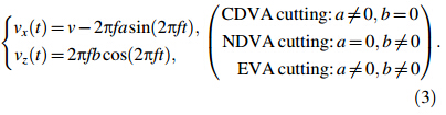
Suppose that the tool vibration trajectory is as follows:
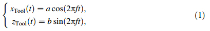
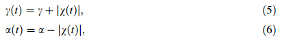
The relative motion speed of tooltip to workpiece is
As summarized in the previous section,the UVA cutting has shown its promising advantages in extending tool life, improving surface finish,reducing cutting forces and enhancing surface integrity. These findings were based on the comparison with a relevant traditional cutting process without tooltip vibration. It is therefore clear that a good selection of the vibration parameters will be important to maximize advantages. An obvious criterion is that the maximum tooltip vibration speed in the cutting direction, vxmax (= 2πfa),should be higher than the tool feed rate [9, 20,27],i.e.,vxmax> v,as otherwise the vibration cannot play a role in cutting. Thus in the discussion in this paper, vxmax> v will be a default assumption.
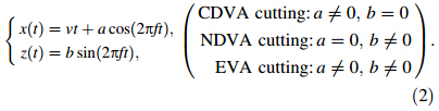
The EVA cutting illustrated in Fig. 1is a typical 2D UVA cutting process. It is easy to understand from Fig. 1 that in a vibration cycle,cutting takes place only when the tooltip wedges into the workpiece at time instant tb,and finishes at time instant te when the tip reaches the maximum amplitude of the vibration in the cutting direction. The tool trajectory in an elliptical cycle indicates that the vertical component of the tool vibration speed near tb is lower than the chip flow speed upward,and the chip flow is constrained by the tool-chip friction. When the vertical component of the vibration speed exceeds the chip flow speed,the tool-chip friction will become in the same direction of the chip flow and start to facilitate the chip removal. Hence,each tooltip vibration cycle in an EVA cutting contains an interval of a negative thrust force, which can bring about a decrease in chip thickness and a reduction of the average cutting force [28, 31, 35]. This is an advantage in comparison with a conventional or a CDVA cutting process. In an EVA cutting interval,the instantaneous direction of the tool motion varies with time, and can be described by

The corresponding instantaneous rake angle γ(t) and clearance angle α(t) are
The vibration-induced thrust force,FZ (t),can influence the stability of the cutting process as well as the surface quality and accuracy of a machined workpiece. To understand the effect,let us consider the tooltip displacements in the vertical direction (i.e.,z-direction in Fig. 1),zCC(t),zlD(t) and zZD(t),in conventional,1D and 2D UVA cutting. They can be expressed respectively as follows [36]:
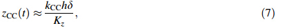
Theoretically,the thrust cutting forces in conventional, 1D and 2D UVA cutting processes can be respectively expressed as [23, 36]
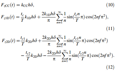
Since the tool vibration frequency is very high,all terms in the summations from n=1to∞in Eqs. (11)-(12) can be neglected.FzlD(t) andFzZD(t) are therefore proportional to tc/T and |tc1-tc2|/T,respectively. Thus |FzZD(t)| \|F z1D (t)<|FzCC(t)|,indicating that UVA cutting has smaller forces and that the 2D UVA mode corresponds to the smallest force. 2.2 Design of UVA cutting systems
A proper design of a UVA cutting system is important to the successful implementation of a UVA cutting process. Two vibration modes have often been used in such designs: the resonant mode [9, 27, 45, 46] and the non-resonant mode [9, 13, 23, 47, 48],of which the former works at discrete natural frequencies of the system structure, whereas the latter works in a continuous frequency range. Thus each of them has its own advantages and limitations. The resonant system is capable of achieving a higher operating frequency and is energetically more efficient. However,it is hard to control the trajectory precisely owing to the nature of the resonant vibrations and the phase lag between the excitation and the mechanical response. The non-resonant system is not limited to a fixed operating frequency and offers a more precise motion control. It is however difficult to produce a high operating frequency because of various technical problems [9, 23, 49]. Thus in the following discussion,we will concentrate on the resonant system.
A resonant 1D UVA system creates a unidimensional tool motion by making the supporting structure vibrate atits resonant frequency. Figure 2 shows a schematic illustration of a typical system and its vibration modes. It usually works at a longitudinal or a bending vibration mode [7, 9, 13, 14, 23, 24, 25, 50]. The ultrasonic generator uses a piezoelectric (PZT) or magnetostrictive actuator to create a reciprocating harmonic motion of high frequency but of low amplitude. The acoustic waveguide booster and horn amplify the ultrasonic motion. To obtain the vibration in a flexible range,the whole body should be supported at the nodal points of its longitudinal or bending vibration mode. A cutting tool is attached at the end of the horn,and is aligned to ensure that the vibration motion is along or normal to the cutting direction [4, 9, 13, 16]. Since the tooltip is expected to experience an acceleration of tens of thousands of gravity,the weight of the cutting tool should usually be minimized in a design [3, 16, 23]. A 1D vibration assisted machining (VAM) system usually operates at frequency of approximately 20-40 kHz and amplitude of 3-20 lm[9, 15, 23].
 |
| Fig. 2 A typical 1D UVA cutting system and its vibration modes |
A resonant 2D UVA system generates an elliptical tool motion through the vibration of the supporting structure atits resonant frequency in two dimensions. It has been reported that compared with a 1D vibration mode,a 2D mode can bring about more advantages in surface finish quality,tool force reduction and tool life extension. Shamoto et al. [17, 27, 28, 29, 37, 38, 40] developed an EVA cutting system in which the PZT actuators were attached to the side faces of a beam structure. Similar cutting systems were also developed by Xu et al. [13] and Lee et al. [51]. Later,Shamoto et al. [17, 39, 41],Moriwaki [52],Nosouhi et al. [53],and Li and Zhang [54] stacked PZT rings into a metal beam to perform the EVA cutting. Kim and Loh [55] developed an L-shaped system for the EVA micro-V grooving. Guo and Ehmann [56, 57] developed a V-shaped system for EVA texturing operation.
Figure 3a shows a typical EVA cutting system with two or four PZT plates being bonded on a cylindrical metal beam [13]. To realize the ultrasonic vibrations in both the cutting and normal directions,two or four alternating current signals with the same frequency but at different phases are applied to the corresponding PZT actuators. When the frequency is set to be the same as or close to the resonant or anti-resonant frequencies of the bending modes of the assembled body (including the actuators, the cylindrical body and the cutting tool),the vibrator will vibrate in two bending modes simultaneously. As a result,the tool at the end of the vibrator vibrates elliptically. To obtain elliptic vibrations in a flexible range, the cylindrical body should be supported at the nodal points of its bending vibration modes. In addition, preloads on the free end can balance the cutting force and improve the stiffness of the vibrator during cutting [13, 58,59].

Figure 3b illustrates a schematic of a typical EVA cutting system [39, 41] where some PZT rings are stacked orthogonally into a metal beam under a preload,and a tool is set at the end of the device. When exciting voltages with some phase shifts are applied,the device will get resonated in the second and fifth resonant modes of the longitudinal and bending vibrations,respectively. The vibrator then vibrates elliptically at a frequency in the ultrasonic range. Figure 3c shows an L-shaped system [55] with two orthogonally connected stacked PZT plates,a preload screw,a cutting tool and a supporting base. Attached at one end of the plate stack is a stainless steel ball to allow a point contact between the plate and the tool holder and to facilitate the sliding of the tool when a lateral force is applied to the PZT stack. When the harmonic excitation voltages are supplied to the PZT plates with a certain phase shift,longitudinal vibrations are generated in two directions,and thus the tooltip will vibrate elliptically. Figure 3d is an illustration of a V-shaped system [56, 57],in which the PZT rings are mounted between the head block and the end mass under a preload through internal bolts. The base block is connected with the system at the nodal points. Driven by the harmonic signals at the system’s resonant frequency,the longitudinal vibrations of the two stacked PZT rings are coupled and magnified by the flexure structure of the head block,leading to an elliptical trajectory of the tooltip.
Kim and Loh [46] developed a T-shaped non-resonant system to work at a high frequency up to 65 kHz,as illustrated in Fig. 3e,which consists of two parallel stacked PZT plates,a cutting tool,and a supporting metal structure. The PZT plates,which enable the low voltage operation, are sandwiched between the assembling structures and are preloaded by a bolt. Under the application of sinusoidal voltages,the PZT plates expand and contract periodically. By controlling the phases between the sinusoidal voltages applied to the actuators,this system allows translating or rotating the cutting tool along a prescribed elliptical path. 3 Applications of UVA cutting
The properties of a workpiece material,e.g.,a ductile material,a brittle material or a composite material,have a direct influence on its machinability. 3.1 UVA cutting of ductile material 3.1.1 Soft metal and alloy Soft ductile materials such as copper,aluminium and mild steel have very good machinability. The 1D UVA cutting of these materials was carried out in Refs. [14, 19, 20, 60], and the performances of CDVA and NDVA cutting with a conventional cutting mode were compared. It was reported that the CDVA cutting is better in terms of cutting force reduction (up to 20%),tool-workpiece friction minimization (up to 90%),chip flow and surface finish improvement. The conclusion is that the 1D UVA cutting could lead to low subsurface deformation and burr free cutting without using coolant. Han et al. [61],Schmu ¨tz et al. [62], Kumar and Hutchings [63] reported similar findings.
The EVA cutting of copper and aluminium workpieces was studied in Refs. [27, 28, 29, 30, 31, 32, 34, 36, 40, 64]. Based on their experimental and theoretical analyses,they found thatcompared with the CDVA and conventional cutting,the EVA cutting could reduce chip thickness and cutting forces significantly. Figure 4a shows a typical result in cutting aluminium 52S with a carbide tool. The CDVA cutting reduced the thrust cutting force to 20% of the corresponding conventional cutting,while the EVA cutting reduced it to only 2%. The finished surface profile measurement (see Fig. 4b) shows that the EVA cutting can extremely improve the machining accuracy. The workpiece shape error in the CDVA and EVA cutting reduced to 21% and 1% of that of the conventional cutting,respectively. In addition,they also found that the EVA cutting could minimize burrs,as shown in Fig. 4c. The burr height after the CDVA cutting was approximately 80% smaller than that in conventional cutting,and that after the EVA cutting suppressed bure height to virtually zero (<1% of that by the conventional cutting). As burr formation is generally postulated to be influenced by compressive and bending stresses induced by cutting in the deformation zone,the results seem to indicate that these stresses are minimized in the UVA cutting processes.

3D microstructures such as arrays of microgrooves, micropyramids,microneedles,microlenses and microprisms are more frequently required in optical,optoelectronic,mechanical and biomedical applications [65]. Due to the merits of low cutting forces,high cutting accuracy and minimized burr formation,the EVA cutting has also been used for the fabrication of miniaturized surfaces [42, 46,55,66-69]. Figure 5a shows an array of microgrooves produced by EVA cutting on brass C2801 [55]. When grooved by conventional cutting,a machined workpiece surface contains side (Poisson) and exit (roll-over) burrs. The EVA cutting,however,reduced cutting forces up to 83%,suppressed the burr formation and improved the groove quality. Guo and Ehmann [56, 57] and Zhang et al. [70] carried out the EVA texturing on aluminium 6061,and studied the effects of tool vibration trajectory,cutting speed,feed rate and tool geometry. They found that the EVA made high quality surfaces in terms of the dimple arrangement and overall surface topography,as shown in Fig. 5b.
 |
| Fig. 5 Microstructure machining |
Hard-to-machine steel such as high carbon and alloy steels are widely used in dies,moulds,tool parts and in automotive/aerospace structures. Direct machining of these materials is cost-effective,and obtaining their high-quality surfaces is always a concern in the manufacturing industry owing to the high tool wear [25, 71]. Although diamond tools have been widely used in cutting non-ferrous materials for high-quality mirror surfaces [71, 72, 73, 74],it cannot be used to cut ferrous materials because of the strong chemical affinity of diamond (carbon) with iron causing excessive tool wear [75, 76, 77]. However,Kumabe [23] reported that with the aid of ultrasonic vibration,the diamond tools could be used to cut steels. Moriwaki and Shamoto [25, 33] then performed the CDVA and EVA cutting of stainless steel and hardened steel with single crystal diamond (SCD) tools, and confirmed that the UVA method was indeed superior in the machining of ferrous materials,i.e.,low cutting force, high quality surface finish and long tool life. In order to reduce production cost,Zhou et al. [72] and Zhang et al. [74] investigated the EVA cutting with polycrystalline diamond (PCD) tools. Their studies concluded that inexpensive PCD tools instead of the SCD tools could be effectively applied to steel machining.
Figure 6 shows a typical scanning electron microscope (SEM) image of a diamond tool after cutting stainless steel SUS304 [72]. It can be seen that the conventional process produces significant wear,but the CDVA cutting minimizes the wear. However,the wear suppression mechanisms of diamond tools in the UVA cutting have not yet been understood. Most people assumed that the intermittentcontact between tool and workpiece material and the reduced cutting forces in UVA cutting led to less heat generation. These in turn lowered down the chemical reaction rate and diamond graphitization rate [9, 25, 33]. Nevertheless,all analytical,numerical and experimental investigations on the UVA cutting have not verified such hypothesis. Zhang et al. [78] carried out certain temperature measurements and cutting energy consumption calculations. Their results unfortunately do not support the previous thesis,but found that the cutting temperature and energy consumption in UVA cutting are not smaller than those in the conventional mode.
 |
| Fig. 6 SEM photographs of worn tools in cutting stainless steel SUS304 [72] |
Extensive studies have been carried out to improve the efficiency of UVA machining of steel using diamond tools, including the influences of cutting and vibration parameters and workpiece hardness on surface quality and tool wear [4, 25, 71, 72, 74, 79, 80, 81, 82]. It has been commonly recognized that (i) UVA cutting has a higher cutting stability as compared with conventional cutting; (ii) 2D UVA cutting is more efficient than 1D mode; (iii) the cutting force,tool wear,surface roughness and tool unstable chatter increase with the increase of tool feed rate,depth of cut and workpiece hardness,but decrease when the tool maximum vibration velocity,vxmax (=2πfa),increases.
In order to transfer lab research outcomes to industrial applications,many efforts have been done on the ultraprecision machining of dies,moulds and tool parts,as well as on the micro/nano functioning structures of different steel materials [43, 70, 73, 83, 84, 85]. Figure 7a shows a result of a tungsten alloy mould (HV380) by EVA ultra-precision turning together with a moulded spherical glass (BK7) lens [83]. Figure 7b displays a tungsten alloy mould with fine grooves,and a moulded part of optical glass BK7 [83], showing that moulds with fine micro structures can be made by the EVA cutting for mass production of optical glass parts. To realize the nano-scale machining of steel materials with the diamond tools,Suzuki et al. [43, 70] proposed a micro/nano structure sculpturing method using EVA cutting,a fast tool servo (FTS) technology (see Fig. 8a). The amplitude of the elliptical vibration was controlled,and hence the depth of cut could be changed quickly to achieve the high performance sculpturing of the micro/nano structures. Figure 8b shows a machined sinusoidal nano structure with the height of 3.5 nm and wavelength of 250 nm,confirming the reliability in making smooth nano structures. Figure 8c shows a microphotograph and a profile of the machined sinusoidal grid surface measured [79]. The periodic nano structure with smooth surface is obtained on the workpiece of the hardened steel SUS420J2. The machined height (1.005 lm) and of wavelength (150 lm) along the cutting direction and the pick feed direction correspond accurately to the expected values.
 |
| Fig. 7 Ultraprecision machined moulds and moulded glass parts [83] |
 |
| Fig. 8 Micro/nano structure sculpturing |
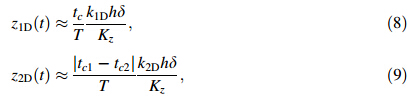
Titanium,cobalt,tungsten and nickel-based superalloys are widely used in the aerospace,energy,medical and automotive industries due to their excellent physical and mechanical properties,including high corrosion resistance, high hardness,high tensile strength,high thermal and wear resistance [4, 86, 87]. However,these good properties are often paired with poor thermal conductivity and high chemical affinity with common cutting tool materials, which impairs their machinability [88]. Typically, machining of these alloys is characterized by low cutting speed and depths of cut,which implies a low material removal rate (MRR) that is not desirable [89]. Additionally,the low thermal conductivity causes concentrated heat zones on the flank and rake faces,accelerates tool wear and severely shortens the tool life. In machining operation, cutting coolant is commonly used to dissipate the heat generated and reduce tool wear. However,the coolant waste is expensive to dispose in an environmentally friendly way. Thus,the UVA cutting is introduced for high efficiency machining of these hard-to-machine alloys. Table 2 compares some performance of the UVA cutting with that of conventional machining.
Brittle materials,such as amorphous materials,single crystal materials,sintered alloys and ceramics,are more and more utilized because of their unique physical and mechanical properties. Especially,the demands for ultraprecision machining of those brittle materials for making sophisticated optical parts,functional components and dies for mass production are increasing. However,because of their low fracture toughness,it is difficult to obtain high quality surfaces of brittle materials by a conventional machining method. Studies have shown that to prevent the fracture-caused damage,a brittle material should be machined in its ductile deformation mode [102, 103, 104, 105, 106, 107]. In practice,the ductile-regime machining frequently remains uneconomical since the critical depth of cut is on the order of 1lm or less,resulting in a small material removal rate and long machining time [3, 108]. The UVA machining was once regarded as inadequate for ductile-machining,because the vibration was normally applied to initiate and facilitate brittle fracture by the impact power of vibration [24]. However,Moriwaki et al. [26] showed experimentally that at a low force level,the vibration did not cause brittle fracture,but increased by several times the critical depth of cut at which ductile-cutting could be achieved. This finding offers a significantly better method to the ductile regime cutting of brittle materials in an economical way. 3.2.1 Amorphous materials
Ductile-cutting of glass was practiced in Refs. [26, 109]who found that the critical depth of cut,the machining accuracy and the tool wear could be significantly improved by applying the vibration on cutting tool. Figure 9 shows the finished micro-groove surface and cutting edge profiles under a critical depth of cut at which the tool radius and feed rate were 2lm and 150 mm/min,respectively. Cracks were observed at the depth of cut greater than 0.26lm in conventional cutting,butit increased to 0.9 lm in EVA cutting. The surface profile formed by the EVA cutting is in good agreement with the designed one,but that finished without vibration is obviously shallower. Such kind of improvement was also observed in the UVA cutting of optical glass BK7 [110],SF6 [111],SF11 [112] and fused silica [3, 51, 113].
 |
| Fig. 9 Ductile-cutting of micro grooves on soda-lime glass [109] |
In the ductile cutting,the viscosity of glass can be reduced under a combination of compressive and shear strain,thus enhancing the plasticisation [114]. The glass can therefore be expected to have better flow characteristics ahead of the immediate cutting edge in the UVA cutting. At the maximum chip thickness,flow happens when the maximum shear strain exceeds a critical level. In addition,the entry speed,maximum speed,contact time and distance during the tool-workpiece contact in a vibration cycle influence chip development [112, 115]. A complete chip is easier to form when both the entry speed and maximum speed are low (thus stress level is low). 3.2.2 Single crystal materials
Single crystal materials,such as silicon,germanium and calcium fluoride,are anisotropic in their physical and mechanical properties. Thus the machining characteristics, such as critical depth of cut,fluctuation of cutting forces, mechanics of chip formation,specific energy,etc.,strongly depend on the crystal orientations and cutting directions [116]. Suzuki et al. [109] carried out the EVA cutting of single crystal calcium fluoride along different crystal orientations. They found that smooth mirror surfaces without fractures could be obtained easily at a practically large depth of cut by the EVA cutting,especially in the½ [121] direction. In contrast,the grooves formed by conventional cutting are with cleavage fractures,and the critical depth of cut for ductile cutting is less than 0.3 lm,as shown in Fig. 10. They also investigated the cutting of single crystal germanium surfaces of (100),(110) and (111) [41]. The critical depth of cut to generate a fracture-free surface could be increased significantly by the EVA cutting. In all orientations on the (100) and (111) surfaces,this depth reached 1lm. This was due to the reduction of instantaneous uncut chip thickness and cutting force in each vibration cycle. To predict the critical undeformed chip thickness in UVA ductile cutting of brittle materials,Zhang et al. [117] developed a specific-cutting-energy based model and studied the material removal process by taking into account the tool geometry,vibration and machining parameters. With the validation of cutting experiments on single crystal silicon in the [110] direction,they found thatin each vibration-cutting cycle,the material would experience an elastic deformation before it was removed plastically,during which additional cutting energy was consumed. In the ductile-cutting mode,the cutting energy consumption includes those for plastic and elastic deformations. The specific cutting energy decreases with the increase of either the instantaneous undeformed chip thickness or nominal feed rate. In addition,the critical undeformed chip thickness increases nonlinearly with the decrease of nominal feed rate. A carefully chosen nominal feed rate can lead to a significantly larger critical undeformed chip thickness if compared to that of conventional cutting.
 |
| Fig. 10 Micro grooves machined on calcium fluoride in its½ [1x1] direction [109] |
Studies on the ductile-cutting of sintered alloys have mainly focused on tungsten carbide,due to the wide applications of this material in tool manufacturing industries for mining and cutting tools,dies,moulds and punches,blades,and so on. Tungsten carbide components are produced by powder metallurgy technology,which is costly and time consuming [118]. Suzuki et al. [109] carried out EVA grooving on tungsten carbide,and found that the ductile machining at the large depth of cut could be realized by applying the elliptical vibration cutting,whereas the conventional cutting could not. A groove formed by conventional cutting was filled with asperities due to micro fractures,while the EVA cutting produced a smooth mirror surface,provided that the vertical vibration amplitude was smaller than the grain size of tungsten carbide. Moreover,at a depth of cut of 1lm,the force in the EVA cutting was 17 times lower than that in the conventional cutting in the cutting direction,14 times lower in the thrust direction. Liu et al. [10, 119] found that there was a transition from ductile mode to brittle mode in both the conventional cutting and UVA cutting,but the critical depth of cut in UVA cutting was several times larger. In addition,the material removal ratio (the volume of material removal to the volume of the machined groove) in UVA grooving is close to 1,indicating a reduction on ploughing effect by the ultrasonic vibration. Nath et al. [120, 121, 122] performed a series of investigations on the effect of cutting conditions,vibration parameters and tool geometries on cutting force,tool wear,chip formation and surface quality in EVA cutting of tungsten carbide with PCD tools. They observed that the EVA cutting resulted in better cutting performance in all of the aspects. There exists a critical depth of cut (4lm in their work) and tool nose radius (0.6 mm in their work) at which the effectiveness of EVA cutting can be fully performed. Decreasing the speed ratio (the ratio of the tool feed rate to the maximum tool vibration speed in cutting direction) can further improve the performance. 3.2.4 Ceramics
To effectively machine ceramic materials,many conventional and unconventional methods have been tried over the past decades [123, 124]. Many studies on zirconia,alumina,silicon nitride and optical ceramics showed that an ultra-precision machining operation without brittle fractures could be obtained by applying ultrasonic vibration on cutting tools [1, 24, 109, 125, 126]. However,no work indicated that the ductile mode machining could be achieved. In the UVA cutting of glass ceramic (VKB MgO) with a carbide tool,Weber et al. [24] found that tool life could increase to 20 times of that in conventional cutting. However,Amini et al. [126] observed that in the UVA cutting of alumina with a PCD insert,tool wear was more significant than that in conventional method. They believed that although the cutting force was significantly decreased,the instant impact forces due to tool vibration were so high that the PCD tool wear was accelerated. 3.3 UVA cutting of composite materials
Composite materials have been extensively used owing to their high specific properties of strength and stiffness to weight ratio. However,being non-homogeneous,anisotropic and reinforced by very abrasive components,these materials are difficult to machine. In using the conventional machining methods,significant damage to composite workpieces often occurs,and cutting tools experience high wear rates [127, 128, 129, 130]. 3.3.1 Metal matrix composites
Investigations into the UVA cutting of metal matrix composites (MMCs) are mainly on SiC particle-reinforced aluminium alloy matrix (SiCp/Al) composites. It has been found that the merits of UVA cutting maintain when the process is applied in cutting MMCs [7, 12, 50, 131, 132, 133]. Figure 11 shows some typical surfaces of a SiCp/Al composite machined by conventional and UVA cutting with PCD tools. Conventional cutting left many pits and cracks in the machined surface,but UVA cutting produced a much better result. Zhao et al. [132] found that the chipping of MMCs was brittle in conventional cutting,but it became ductile in UVA cutting (see Fig. 12). They also found that UVA cutting could reduce the influence of tearing,plastic deformation and cutting edge built-up. The surface integrity machined by PCD tools is better than that by carbide tools [132, 133].
 |
| Fig. 11 Surfaces of SiCp/Al composite machined by a conventional and b UVA cutting [132] |
 |
| Fig. 12 Cutting chips in a conventional and b UVA cutting of a SiCp/Al composite [132] |
To effectively machine FRP composites,Takeyama and Iijima [134],and Kim and Lee [20150301] carried out CDVA cutting of glass and carbon FRPs,respectively. They observed that the cutting force and surface quality can be largely improved. Xu et al. [13, 136, 137] investigated CDVA,NDVA and EVA cutting of FRPs through a series of numerical and experimental studies,and found that the vibration in the cutting direction (CDVA) was more effective in reducing the cutting force,but that normal to the cutting direction (NDVA) had the advantage of chip removal. When vibration is applied to both the directions in the EVA cutting,an optimal cutting process can be reached,providing much smaller cutting forces,a much improved surface integrity,and an extended tool life. In addition,the ratio of the tool feed rate to the maximum vibration velocity in the cutting direction,and the ratio of the cutting distance in a single tool vibration cycle to the fibre diameter are the key parameters. To maximize the advantage of EVA cutting,it is necessary that these two parameters are below their critical values.
Figure 13 shows some snapshots and collected chips in Figure 13 shows some snapshots and collected chips in different cutting methods. Due to the continuous ploughing motion of the cutting edge,a large quantity of chips appeared and accumulated in front of the cutting tip in the conventional cutting. With the application of the vibration in the CDVA and NDVA cutting,the chip size decreased and no chip accumulation occurred in front of the cutting tool. However,only the EVA cutting produced the smallestchips and they were always removed instantly. As for the finished surface (see Fig. 14),the tool pulled the fibres out which generated deep damages to the subsurface in the conventional cutting,forming large fibre-matrix clusters and a rough surface. The CDVA and NDVA cutting improved the machined surface quality,while the best results were by the EVA cutting,which not only made surface much smoother,but also minimized the debonding, leading to high surface integrity.
 |
| Fig. 13 Some snapshots and collected chips in different cutting methods [13] |
 |
| Fig. 14 Surfaces of carbon FRPs machined by different methods [13] |
The cutting tool geometries before and after cutting, Fig. 15,show that the tool experienced significant crater and flank wear in conventional cutting. With EVA,however,because of the merit of small chips and cutting forces, the tool wear is greatly improved.
 |
| Fig. 15 Wear of the cutting tools before and after cutting [13] |
To understand the material removal mechanisms,Xu and Zhang investigated the process of UVA cutting of FRPs through a mechanics analysis [137] and a 3D microstructure-based finite element (FE) simulation [13, 136]. Figure 16 shows the FE simulation results of fibre fracture in different cutting methods. In the conventional cutting,the wedging of the cutting edge does not remove the fractured fibres effectively,but pushes the broken fibre segments into the zone in front of the cutting edge. This leads to obvious fibre-bending ahead of the cutting zone, brings about severe damages to the neighbouring fibres and the matrix material,and causes the fibres to crack even in the deep subsurface. In the CDVA cutting,due to the high vibration velocity and microscale vibration amplitude, some localized deformation zones appear and the vibration breaks a feed step down to many intermittent cutting actions. However,fibre fracture in the deep subsurface still occurs,caused by the reciprocating motion of the cutting edge. In the NDVA cutting,the fibre facture becomes localized,because the tool-fibre friction caused by the vertical vibration motion of the cutting edge brings about additional tension and compression cycles in the fibre, particularly at the fibre-tool contact surface. However,the vertical vibration does not change the horizontal wedging force of the tooltip. As a result,the stresses in the fibres ahead of the cutting zone are greater than those under the CDVA mode. In the EVA cutting,the chipping and breakage of a fibre are much more localized in comparison with the other cases. Due to the simultaneous motion of the tooltip in both the cutting and vertical directions,stresses are concentrated in a very narrow region around the tipfibre interaction zone. The fibre is fractured into much smaller pieces,which has largely improved the surface integrity of the finished surface. Meanwhile,it can be clearly seen that the fibres that are not in direct contact with the tooltip have very low stresses. The fibre-bending observed in the previous three cases becomes minimal.
 |
| Fig. 16 Fibre fracture in different cutting methods [13] |
As a non-traditional high efficiency machining method, UVA cutting has been widely investigated. Its high machining capabilities,including low cutting forces,long tool life,high surface integrity and excellent cutting accuracy,are effective on the machining of many types of materials from macro,micro to nano-scales,and have shown an enormous potential in industrial applications. However,many issues need to be clarified before a UVA process can be optimized. The following are some of the authors’ personal perspectives for further research:
(i) In general,high vibration frequency and amplitude would improve the cutting performance of a UVA system. However,due to the limitations of hardware structures and capacity of PZT materials,developing UVA systems of high vibration frequency and amplitude is a challenge.
(ii) Fundamental studies on the material removal mechanisms of difficult-to-machine materials are limited. For example,although UVA diamond tools have been found to be applicable to the machining of even ferrous metals at low tool wear rates,the mechanisms behind, especially the role of temperature rise,are unclear.
(iii) Compared with a conventional machining process, UVA cutting can often have a much greater critical depth of cut according to experimental observations. In-depth understanding of the mechanisms is unavailable.
(iv) UVA cutting on composites is still at its early stage. The machining physics and mechanics need to be explored. A good example is the heat generation and its effect on the cutting performance.
Acknowledgements The authors appreciate the Australian Research Council for its financial support to this work.| 1. | Kumabe J, Fuchizawa K, Soutome T et al (1989) Ultrasonic superposition vibration cutting of ceramics. Precis Eng11:71-76 |
| 2. | Xiao M, Karube S, Soutome T et al (2002) Analysis of chatter suppression in vibration cutting. Int J Mach Tool Manuf 42:1677-1685 |
| 3. | Zhou M, Wang XJ, Ngoi BKA et al (2002) Brittle-ductile transition in the diamond cutting of glasses with the aid of ultrasonic vibration. J Mater Process Technol 121:243-251 |
| 4. | Babitsky VI, Kalashnikov AN, Meadows A et al (2003) Ultrasonically assisted turning of aviation materials. J Mater Process Technol 132:157-167 |
| 5. | Fang FZ, Liu XD, Lee LC (2003) Micro-machining of optical glasses: a review of diamond-cutting glasses. Sadhana 28:945-955 |
| 6. | Mitrofanov AV, Ahmed N, Babitsky VI et al (2005) Effect of lubrication and cutting parameters on ultrasonically assisted turning of Inconel 718. J Mater Process Technol 162:649-654 |
| 7. | Zhong ZW, Lin G (2006) Ultrasonic assisted turning of an aluminium-based metal matrix composite reinforced with SiC particles. Int J Adv Manuf Technol 27:1077-1081 |
| 8. | Rahman CNM, Andrew SSK (2007) A study on ultrasonic vibration cutting of low alloy steel. J Mater Process Technol 192:159-165 |
| 9. | Brehl DE, Dow TA (2008) Review of vibration-assisted machining. Precis Eng 32:153-172 |
| 10. | Liu K, Li XP, Rahman M (2008) Characteristics of ultrasonic vibration-assisted ductile mode cutting of tungsten carbide. Int J Adv Manuf Technol 35:833-841 |
| 11. | Maurotto A, Muhammad R, Roy A et al (2012) Comparing machinability of Ti-15-3-3-3 and Ni-625 alloys in UAT. Proc Cirp 1:330-335 |
| 12. | Dong GJ, Zhang HJ, Zhou M et al (2013) Experimental investigation on ultrasonic vibration-assisted turning of SiCp/Al composites. Mater Manuf Process 28:999-1002 |
| 13. | Xu W, Zhang LC, Wu Y (2014) Elliptic vibration-assisted cutting of fibre-reinforced polymer composites: understanding the material removal mechanisms. Compos Sci Technol 92:103-111 |
| 14. | Kumabe J, Masuko M (1958) Study on the ultrasonic cutting (1st report). Trans Jpn Soc Mech Eng 24:109-114 |
| 15. | Thoe TB, Aspinwall DK, Wise MLH (1998) Review on ultrasonic machining. Int J Mach Tool Manuf 38:239-255 |
| 16. | Jin M, Murakawa M (2001) Development of a practical ultrasonic vibration cutting tool system. J Mater Process Technol 113:342-347 |
| 17. | Shamoto E, Suzuki N, Moriwaki T et al (2002) Development of ultrasonic elliptical vibration controller for elliptical vibration cutting. CIRP Ann 51:327-330 |
| 18. | Ostasevicius V, Gaidys R, Rimkeviciene J et al (2010) An approach based on tool mode control for surface roughness reduction in high-frequency vibration cutting. J Sound Vib 329:4866-4879 |
| 19. | Kumabe J (1961) Study on ultrasonic cutting: 2nd report, the mechanism of tool rest for ultrasonic cutting. Trans Jpn Soc Mech Eng 27:1389-1396 |
| 20. | Kumabe J (1961) Study on ultrasonic cutting: 3rd report. An analysis of the mechanism of ultrasonic cutting. Trans Jpn Soc Mech Eng 27:1396-1404 |
| 21. | Balamuth L (1966) Ultrasonic assistance to conventional metal removal. Ultrasonics 4:125-130 |
| 22. | Skelton RC (1968) Turning with an oscillating tool. Int J Mach Tool Des Res 8:239-259 |
| 23. | Kumabe J (1979) Fundamentals and applications: ultrasonic cutting. Jikkyou Publishing Co., 1979 |
| 24. | Weber H, Herberger J, Pilz R (1984) Turning of machinable glass ceramics with an ultrasonically vibrated tool. CIRP Ann 33:85-87 |
| 25. | Moriwaki T, Shamoto E (1991) Ultraprecision diamond turning of stainless steel by applying ultrasonic vibration. CIRP Ann 40:559-562 |
| 26. | Moriwaki T, Shamoto E, Inoue K (1992) Ultraprecision ductile cutting of glass by applying ultrasonic vibration. CIRP Ann 41:141-144 |
| 27. | Shamoto E, Moriwaki T (1994) Study on elliptical vibration cutting. CIRP Ann 43:35-38 |
| 28. | Moriwaki T, Shamoto E (1995) Ultrasonic elliptical vibration cutting. CIRP Ann 44:31-34 |
| 29. | Shamoto E, Morimoto Y, Moriwaki T (1996) Elliptical vibration cutting (1st report): cutting principle and basic performance. J Jpn Soc Precis Eng 62:1127-1131 |
| 30. | Shamoto E, Suzuki N, Hino R (2007) Simulation of elliptical vibration cutting process with thin shear plane model. In: Proceedings of ASPE, pp 64-69. |
| 31. | Shamoto E, Ma C, Moriwaki T (1999) Elliptical vibration cutting (3rd report): application to three-dimensional cutting and investigation of practical effects. J Jpn Soc Precis Eng 65:586-591 |
| 32. | Shamoto E, Morimoto Y, Moriwaki T (1999) Elliptical vibration cutting (2nd report): study on effects of vibration conditions. J Jpn Soc Precis Eng 65:411-417 |
| 33. | Shamoto E, Moriwaki T (1999) Ultraprecision diamond cutting of hardened steel by applying elliptical vibration cutting. CIRP Ann 48:441-444 |
| 34. | Shamoto E, Suzuki N, Moriwaki T et al (2001) Elliptical vibration cutting (4th report): development of tool vibration control system and its application to ultraprecision cutting. J Jpn Soc Precis Eng 67:1871-1877 |
| 35. | Ma C, Shamoto E, Moriwaki T (2004) Study on the improvement of machining system stability by applying ultrasonic elliptical vibration cutting. Acta Armamentarii 25:752-756 |
| 36. | Ma CX, Shamoto E, Moriwaki T et al (2004) Study of machining accuracy in ultrasonic elliptical vibration cutting. Int J Mach Tool Manuf 44:1305-1310 |
| 37. | Shamoto E, Suzuki N (2006) Ultraprecision cutting by applying elliptical vibration. J Jpn Soc Precis Eng 72:440-443 |
| 38. | Shamoto E, Suzuki N (2009) Development of elliptical vibration cutting technology and its application to ultraprecision/micro machining of hard/brittle materials. Ultra-Precis Mach Technol 69-70:133-137 |
| 39. | Suzuki N, Haritani M, Yang J et al (2007) Elliptical vibration cutting of tungsten alloy molds for optical glass parts. CIRP Ann 56:127-130 |
| 40. | Shamoto E, Suzuki N, Tsuchiya E et al (2005) Development of 3 DOF ultrasonic vibration tool for elliptical vibration cutting of sculptured surfaces. CIRP Ann 54:321-324 |
| 41. | Suzuki N, Yan Z, Hino R et al (2006) Ultraprecision micromachining of single crystal germanium by applying elliptical vibration cutting. In: 2006 IEEE international symposium on micro-nanomechatronics and human science, pp 41-46 |
| 42. | Kim GD, Loh BG (2010) Machining of micro-channels and pyramid patterns using elliptical vibration cutting. Int J Adv Manuf Technol 49:961-968 |
| 43. | Suzuki N, Yokoi H, Shamoto E (2011) Micro/nano sculpturing of hardened steel by controlling vibration amplitude in elliptical vibration cutting. Precis Eng 35:44-50 |
| 44. | Zhang JG, Suzuki N, Kato T et al (2012) Influence of material composition on ductile machining of tungsten carbide in elliptical vibration cutting. Key Eng Mater 523-524:113-118 |
| 45. | Ahn JH, Lim HS, Son SM (1999) Improvement of micro-machining accuracy by 2-dimensional vibration cutting. In: Proceedings of the fourteenth annual meeting of the ASPE, pp 150-153. |
| 46. | Kim GD, Loh BG (2007) An ultrasonic elliptical vibration cutting device for micro V-groove machining: kinematical analysis and micro V-groove machining characteristics. J Mater Process Technol 190:181-188 |
| 47. | Dow TA, Cerniway M, Sohn A et al (2001) Vibration assisted diamond turning using elliptical tool motion. In: Proceedings of the 2001 ASPE annual meeting, pp 92-97. |
| 48. | Joshi RS, Singh H (2011) Piezoelectric transducer based devices for development of a sustainable machining system: a review. IEEE Int Ferro |
| 49. | Harada K, Sasahara H (2009) Effect of dynamic response and displacement/stress amplitude on ultrasonic vibration cutting. J Mater Process Technol 209:4490-4495 |
| 50. | Zhong ZW, Lin G (2005) Diamond turning of a metal matrix composite with ultrasonic vibrations. Mater Manuf Process 20:727-735 |
| 51. | Lee JS, Lee DW, Jung YH et al (2002) A study on microgrooving characteristics of planar lightwave circuit and glass using ultrasonic vibration cutting. J Mater Process Technol 130:396-400 |
| 52. | Moriwaki T (2010) Development of 2DOF ultrasonic vibration cutting device for ultraprecision elliptical vibration cutting. Key Eng Mater 447-448:164-168 |
| 53. | Nosouhi R, Behbahani S, Amini S et al (2013) Experimental and analytical study of the elliptical vibration-assisted turning process with the dynamic friction model. Proc Inst Mech Eng Part B: J Eng Manuf 0954405413508943:1-10 |
| 54. | Li X, Zhang DY (2006) Ultrasonic elliptical vibration transducer driven by single actuator and its application in precision cutting. J Mater Process Technol 180:91-95 |
| 55. | Kim GD, Loh BG (2008) Characteristics of elliptical vibration cutting in micro-V grooving with variations in the elliptical cutting locus and excitation frequency. JMicromechMicroeng 18:751-790 |
| 56. | Guo P, Ehmann KF (2013) Development of a tertiary motion generator for elliptical vibration texturing. Precis Eng 37:364-371 |
| 57. | Guo P, Ehmann KF (2013) An analysis of the surface generation mechanics of the elliptical vibration texturing process. Int J Mach Tool Manuf 64:85-95 |
| 58. | Xu W, Wu Y (2011) A new through-feed centerless grinding technique using a surface grinder. J Mater Process Technol 211:1599-1605 |
| 59. | Xu W, Wu Y (2011) A new in-feed centerless grinding technique using a surface grinder. J Mater Process Technol 211:141-149 |
| 60. | Kumabe J (1964) Few novel machine tools to be used for supersonically vibrating cut. J Jpn Soc Mech Eng 67:85-92 |
| 61. | Han L, Xu WL, Tso SK (1998) Ultrasonically assisted and piezoelectric actuators integrated cutting tool. Jpn J Appl Phys 37(8):4616-4619 |
| 62. | Schmütz J, Brinksmeier E, Bischoff E (2001) Sub-surface deformation in vibration cutting of copper. Precis Eng 25:218-223 |
| 63. | Kumar VC, Hutchings IM (2004) Reduction of the sliding friction of metals by the application of longitudinal or transverse ultrasonic vibration. Tribol Int 37:833-840 |
| 64. | Ma C, Shamoto E, Moriwaki T et al (2005) Suppression of burrs in turning with ultrasonic elliptical vibration cutting. Int J Mach Tools Manuf 45:1295-1300 |
| 65. | Yan J, Oowada T, Zhou T et al (2009) Precision machining of microstructures on electroless-plated NiP surface for molding glass components. J Mater Process Tech 209:4802-4808 |
| 66. | Gao GF, Zhao B, Jiao F et al (2002) Research on the influence of the cutting conditions on the surface microstructure of ultra-thin wall parts in ultrasonic vibration cutting. J Mater Process Tech 129:66-70 |
| 67. | Dornfeld D, Min S, Takeuchi Y (2006) Recent advances in mechanical micromachining. CIRP Ann 55:745-768 |
| 68. | Kim GD, Loh BG (2007) Characteristics of chip formation in micro V-grooving using elliptical vibration cutting. J Micromech Microeng 17:1458-1466 |
| 69. | Shimizu J, Yamamoto T, Zhou LB et al (2013) Fabrication of surface microtexture by vibration assisted cutting. Adv Mater Res 797:638-641 |
| 70. | Zhang J, Suzuki N, Shamoto E (2013) Investigation on machining performance of amplitude control sculpturing method in elliptical vibration cutting. Proc CIRP 8:327-332 |
| 71. | Brinksmeier E, Glabe R (1999) Elliptical vibration cutting of steel with diamond tools. In: Proceedings of the fourteenth annual meeting of the ASPE, pp 163-166. |
| 72. | Zhou M, Eow YT, Ngoi BKA et al (2003) Vibration-assisted precision machining of steel with PCD tools. Mater Manuf Process 18:825-834 |
| 73. | Klocke F, Dambon O, Bulla B (2010) Diamond turning of aspheric steel molds for optics replication. Proc SPIE 75900B1-75900B10 |
| 74. | Zhang XQ, Kumar AS, Rahman M et al (2011) Experimental study on ultrasonic elliptical vibration cutting of hardened steel using PCD tools. J Mater Process Technol 211:1701-1709 |
| 75. | Paul E, Evans CJ, Mangamelli A et al (1996) Chemical aspects of tool wear in single point diamond turning. Precis Eng 18:4-19 |
| 76. | Li ZJ, Fang FZ, Gong H et al (2013) Review of diamond-cutting ferrous metals. Int J Adv Manuf Technol 68:1717-1731 |
| 77. | Chen Y, Zhang L (2013) Polishing of diamond materials: mechanisms, modeling and implementation. Springer, New York |
| 78. | Zhang XQ, Liu K, Kumar AS et al (2014) A study of the diamond tool wear suppression mechanism in vibration-assisted machining of steel. J Mater Process Technol 214:496-506 |
| 79. | Suzuki N, Nakamura A, Shamoto E et al (2003) Ultraprecision micromachining of hardened steel by applying ultrasonic elliptical vibration cutting. In: Mhs2003: proceedings of 2003 international symposium on micromechatronics and human science, pp 221-226. |
| 80. | Xiao M, Sato K, Karube S et al (2003) The effect of tool nose radius in ultrasonic vibration cutting of hard metal. Int J Mach Tool Manuf 43:1375-1382 |
| 81. | Klocke F, Dambon O, Bulla B et al (2008) Ultrasonic assisted turning of hardened steel with mono-crystalline diamond. In: Proceedings of the 23rd annual ASPE meeting, Portland, Oregon |
| 82. | Xie XD, Yong L, Camvinh D et al (2012) Experiment and discussion on ultrasonic vibration-assisted single point diamond turning of die steels. Ultra-Precis Mach Technol 497:1-5 |
| 83. | Shamoto E, Suzuki N (2008) Elliptical vibration cutting of hard mold materials. In: Optical fabrication and testing, Optical Society of America, pp OTuB1. |
| 84. | Bulla B, Klocke F, Dambon O et al (2012) Ultrasonic assisted diamond turning of hardened steel for mould manufacturing. In: Proceedings of precision engineering and nanotechnology (Aspen2011), 516, pp 437-442. |
| 85. | Fang FZ, Zhang XD, Weckenmann A et al (2013) Manufacturing and measurement of freeform optics. CIRP Ann 62:823-846 |
| 86. | Babitsky VI, Mitrofanov AV, Silberschmidt VV (2004) Ultrasonically assisted turning of aviation materials: simulations and experimental study. Ultrasonics 42:81-86 |
| 87. | Ezugwu EO (2005) Key improvements in the machining of difficult-to-cut aerospace superalloys. Int J Mach Tool Manuf 45:1353-1367 |
| 88. | Maurotto A, Roy A, Babitsky VI et al (2012) Analysis of machinability of Ti- and Ni-based alloys. Solid State Phenomena 188:330-338 |
| 89. | Ezugwu EO, Bonney J, Yamane Y (2003) An overview of the machinability of aeroengine alloys. J Mater Process Technol 134:233-253 |
| 90. | Koshimizu S (2009) Ultrasonic vibration-assisted cutting of titanium alloy. Key Eng Mater 389-390:277-282 |
| 91. | Wu YB, Niu JT, Fujimoto M et al (2013) Fundamental machining characteristics of ultrasonic assisted turning of titanium alloy Ti-6Al-4V. Adv Mater Res 797:344-349 |
| 92. | Patil S, Joshi S, Tewari A et al (2014) Modelling and simulation of effect of ultrasonic vibrations on machining of Ti6Al4V. Ultrasonics 54:694-705 |
| 93. | Muhammad R, Hussain MS, Maurotto A et al (2014) Analysis of a free machining alpha?beta titanium alloy using conventional and ultrasonically assisted turning. J Mater Process Technol214:906-915 |
| 94. | Muhammad R, Maurotto A, Roy A et al (2012) Hot ultrasonically assisted turning of beta-Ti alloy. Proc CIRP 1:336-341 |
| 95. | Maurotto A, Muhammad R, Roy A et al (2013) Enhanced ultrasonically assisted turning of a beta-titanium alloy. Ultrasonics53:1242-1250 |
| 96. | Muhammad R, Maurotto A, Demiral M et al (2014) Thermally enhanced ultrasonically assisted machining of Ti alloy. CIRP J Manuf Sci Technol 7:159-167 |
| 97. | Kim GD, Loh BG (2011) Direct machining of micro patterns on nickel alloy and mold steel by vibration assisted cutting. Int J Precis Eng Manuf 12:583-588 |
| 98. | Hsu CY, Lin YY, Lee WS et al (2008) Machining characteristics of Inconel 718 using ultrasonic and high temperature-aided cutting. J Mater Process Technol 198:359-365 |
| 99. | Song Y, Park CH, Moriwaki T (2010) Mirror finishing of Co- Cr-Mo alloy using elliptical vibration cutting. Precis Eng34:784-789 |
| 100. | Zhang YL, Zhou ZM, Lv Y et al (2013) Wear behavior of natural diamond tool in cutting tungsten-based alloy. Int J Adv Manuf Technol 69:329-335 |
| 101. | Suzuki N, Yan Z, Haritani M et al (2007) Ultraprecision machining of tungsten alloy by applying ultrasonic elliptical vibration cutting. J Jpn Soc Precis Eng 73:360-366 |
| 102. | Zhang L, Mahdi M (1996) The plastic behaviour of silicon subjected to micro-indentation. J Mater Sci 31:5671-5676 |
| 103. | Zarudi I, Zhang LC (2000) On the limit of surface integrity of alumina by ductile-mode grinding. J Eng Mater 122:129-134 |
| 104. | Zarudi I, Zhang L (1999) Initiation of dislocation systems in alumina under single-point scratching. J Mater Res 14:1430-1436 |
| 105. | Zarudi I, Zhang L, Cockayne D (1998) Subsurface structure of alumina associated with single-point scratching. J Mater Sci33:1639-1645 |
| 106. | Zarudi I, Zhang L, Mai YW (1996) Subsurface damage in alumina induced by single-point scratching. J Mater Sci31:905-914 |
| 107. | Neo WK, Kumar AS, Rahman M (2012) A review on the current research trends in ductile regime machining. Int J Adv Manuf Technol 63:465-480 |
| 108. | Blake PN, Scattergood RO (1990) Ductile-regime machining of germanium and silicon. J Am Ceram Soc 73:949-957 |
| 109. | Suzuki N, Masuda S, Haritani M et al (2004) Ultraprecision micromachining of brittle materials by applying ultrasonic elliptical vibration cutting. In: Proceedings of the 2004 international symposium on micro-nanomechatronics and human science, pp 133-138. |
| 110. | Zhou M, Liu XD, Huang SN (2006) Ultraprecision cutting of glass BK7. Key Eng Mater 315-316:536-540 |
| 111. | Zhao H, Zhou M (2008) An experimental study on diamond cutting of optical glass. Key Eng Mater 375-376:211-215 |
| 112. | Zhou M, Liang YC, Huang SN (2008) Ultraprecision ductileregime cutting of optical glass. Key Eng Mater 364:69-73 |
| 113. | Gan J, Wang X, Zhou M et al (2003) Ultraprecision diamond turning of glass with ultrasonic vibration. Int J Adv Manuf Technol 21:952-955 |
| 114. | Giovanola J, Finnie I (1980) On the machining of glass. J Mater Sci 15:2508-2514 |
| 115. | Klocke F, Demmer A, Heselhaus M (2004) Material removal mechanisms in ultrasonic-assisted diamond turning of brittle materials. Int J Mater Prod Technol 20:231-238 |
| 116. | Leung TP, Lee WB, Lu XM (1998) Diamond turning of silicon substrates in ductile-regime. J Mater Process Technol 73:42-48 |
| 117. | Zhang XQ, Arif M, Liu K et al (2013) A model to predict the critical undeformed chip thickness in vibration-assisted machining of brittle materials. Int J Mach Tool Manuf 69:57-66 |
| 118. | Liu K, Li XP (2001) Ductile cutting of tungsten carbide. J Mater Process Technol 113:348-354 |
| 119. | Liu K, Li XP, Rahman M et al (2004) Study of ductile mode cutting in grooving of tungsten carbide with and without ultrasonic vibration assistance. Int J Adv Manuf Technol 24:389-394 |
| 120. | Nath C, Rahman M, Neo KS (2009) Machinability study of tungsten carbide using PCD tools under ultrasonic elliptical vibration cutting. Int J Mach Tool Manuf 49:1089-1095 |
| 121. | Nath C, Rahman M, Neo KS (2009) A study on the effect of tool nose radius in ultrasonic elliptical vibration cutting of tungsten carbide. J Mater Process Technol 209:5830-5836 |
| 122. | Nath C, Rahman M, Neo KS (2009) A study on ultrasonic elliptical vibration cutting of tungsten carbide. J Mater Process Technol 209:4459-4464 |
| 123. | Bifano TG, Dow TA, Scattergood RO (1991) Ductile-regime grinding: a new technology for machining brittle materials. J Eng Ind 113:184-189 |
| 124. | Tuersley IP, Jawaid A, Pashby IR (1994) Various methods of machining advanced ceramic materials—review. J Mater Process Technol 42:377-390 |
| 125. | Fess E, Bechtold R, Bechtold M et al (2013) Ultrasonic processing of hard materials for conformal optics. Proc SPIE870811-870815 |
| 126. | Amini S, Khosrojerdi MR, Nosouhi R et al (2014) An experimental investigation on the machinability of Al2O3 in vibrationassisted turning using PCD tool. Mater Manuf Process29:331-336 |
| 127. | Zhang ZF, Zhang LC, Mai YW (1995) Wear of ceramic particlereinforced metal-matrix composites. 1. Wear mechanisms. J Mater Sci 30:1961-1966 |
| 128. | Teti R (2002) Machining of composite materials. CIRP Ann51:611-634 |
| 129. | Wang XM, Zhang LC (2003) An experimental investigation into the orthogonal cutting of unidirectional fibre reinforced plastics. Int J Mach Tool Manuf 43:1015-1022 |
| 130. | Pramanik A, Zhang LC, Arsecularatne JA (2008) Machining of metal matrix composites: effect of ceramic particles on residual stress, surface roughness and chip formation. Int J Mach Tool Manuf 48:1613-1625 |
| 131. | Liu CS, Zhao B, Gao GF et al (2002) Research on the characteristics of the cutting force in the vibration cutting of a particlereinforced metal matrix composites SiCp/Al. J Mater Process Technol 129:196-199 |
| 132. | Zhao B, Liu CS, Zhu XS et al (2002) Research on the vibration cutting performance of particle reinforced metallic matrix composites SiCp/Al. J Mater Process Technol 129:380-384 |
| 133. | Cheng X, Ma X (2010) Microstructure analysis of SiCp/Al composites with ultrasonic vibration turning. In: 3rd IEEE international conference on biomedical engineering and informatics (BMEI), pp 2321-2324. |
| 134. | Takeyama H, Iijima N (1988) Machinability of glassfiber reinforced plastics and application of ultrasonic machining. CIRP Ann 37:93-96 |
| 135. | Kim JD, Lee ES (1994) A study of the ultrasonic-vibration cutting of carbon-fiber-reinforced plastics. J Mater Process Technol 43:259-277 |
| 136. | Xu WX, Zhang L, Wu YB (2012) Micromechanical modelling of elliptic vibration-assisted cutting of unidirectional FRP composites. Adv Mater Res 591:531-534 |
| 137. | Xu W, Zhang L (2014) On the mechanics and material removal mechanisms of vibration-assisted cutting of unidirectional fibrereinforced polymer composites. Int J Mach Tools Manuf80:1-10" |