 2015, Vol. 3
The article information
- Hirpa G. Lemu
- Advances in numerical computation based mechanical system design and simulation
- Advances in Manufacturing, 2015, 3(2): 130-138
- http://dx.doi.org/10.1007/s40436-015-0110-9
-
Article history
- Received: 2015-01-30
- Accepted: 2015-04-23
- Published online: 2013-05-23


It is widely accepted that manufacturing is the driver of the developments of world economy and hence highly competitive. Contrary to the competitive factors of the last century such as quality and prices, today's companies need to be continuously adaptive and innovative in order to cope with the rapidly changing global market. The current turbulent and globalized manufacturing, in particular, demands an ever-increasing higher degree of product customization and personalization where the traditional design method cannot cope with the demands and the value of simulationbased engineering is obviously very high. Today, numerical computation based simulation, which consists of a set of technological tools and methods for implementation in digital design, analysis and manufacturing, allows the experimentation and validation of products, processes and system design as well as their configuration.
As an emerging technology, numerical computationbased simulation supports digital prototyping of complex engineering systems. It, in general, represents a huge paradigm shift in mechanical system design where product design and manufacturing process is validated and verified using digital prototypes. This highly benefits research on mechanical systems that operate in unfriendly areas for experimenting on physical prototypes. For instance, offshore- based renewable converters such as wave and offshore wind energy converters are dynamic systems demanding complex and costly design validation and verification. A well-developed simulation-based engineering capacity will enable effective study in a virtual world and optimization for improved performance [1] of the dynamic and nonlinear behavior of these systems.
When implementing computational modeling and simulation approach, there is a fundamental issue to be addressed. Reliable results can be obtained only when the developed model can represent the physical reality as close as possible. This depends on the in-depth understanding of the involved multidisciplinary environment. As the abovementioned energy converters operate under different physical environments, the physics of the energy conversion process widely varies, and a wide range of modeling and simulation techniques are employed.
There exist three main groups of simulation packages for energy converter systems (ECSs): (i) proprietary software that is used under license agreements; (ii) open source software; (iii) free software [2]. The proprietary software is general purpose and hence does not lend itself for altering the simulation algorithm. This makes this group of software mostly unsuitable for research work [3]. The open source and free software, on the other hand, allows the user to customize the source code and add own algorithms or toolboxes. This allows fitting the tools for specific needs in teaching or research.
This article focuses on selected numerical computation techniques in analysis and simulation of mechanical systems from the designers' point of view. It gives highlights on current developments, research activities and future directions in numerical simulation as applied in mechanical engineering field. The article first presents short overview of trends in numerical computation methods and then introduces the finite element and multibody dynamics simulation techniques. Finally, the role and case study applications of these techniques to simulate wind and wave energy conversion process are discussed. 2 Trends in mechanical system simulation
Numerical computation techniques involve multidisciplinary fields that demand knowledge and competence in, among others, computer science, CAD, modeling techniques, mechanics and numerical methods. The techniques are applied in mechanical system simulation through the relevant physical laws, geometrical shapes or profiles and appropriate materials to model and simulate the performance characteristics of the system. Based on the simulation results, appropriate measures can be taken to reduce mechanical losses such as in bearings and other components of the transmission system.
As a result of the advances in computational methods such as finite element analysis (FEA), computational fluid dynamics (CFD) and multibody dynamics (MBD) simulation tools, performing numerical computation-based modeling and analysis in engineering is the reality of today's and as well as tomorrow's tool of advanced research. Because of the progressive developments in numerical simulation, the sphere of simulation-based research and industrial application are widen. The numerical simulationbased engineering research can be employed in one or several of the areas, as illustrated in Fig. 1.
 |
| Fig. 1 Partial overview of research areas within mechanical simulation |
Introduction of numerical computation based on engineering in design field implies two main transitions. One is the paradigm shift from traditional design philosophy that is trial-and-error based design iteration to a simulation-based design through analysis. Another is the transition from physical prototypes based on design validation and verification to the virtual engineering one in a digital world.
Both transitions highly contribute to improved quality and reduced product cost as a result of minimized physical tests. Further, numerical computation enables digital evaluation of design alternatives, easier handling of multidisciplinary systems, and simplified creation and reuse of existing design models.
The motivation of using any of the simulation tools in Fig. 1 varies, both from the user's and developer's point of view. A recent survey work [4] indicates that the three major application areas, in descending order are the mechanical/ structural analysis, fatigue and the thermal/fluid analysis. In the following section, two of the mechanical system analysis and simulation tools, i.e., finite element methods (FEMs) and MBD simulation are briefly explained. 2.1 FEA
Application of FEA concept in mechanical system analysis dates back to the work of Courant [5] who in early 1940s explained how a given structure could be subdivided into finite sections and solved using piecewise polynomial variations. By the principle of minimum potential energy (MPE), a fundamental introduction was presented on how to deal with complex problems as boundary value problems and eigenvalue problems.
Nowadays, the basics of FEA are widely covered in diverse literature and textbooks. For most applications, the fundamental formulation of FEM is given by the stiffness relation (Eq. (1)), which is used as a benchmark relation for other problem types.

Figure 2 depicts the general workflow of the procedure for linear FEA. The shown steps are common for most applications and the solution process is performed automatically, even by users with minor knowhow about the underlying mathematical and physical laws. Based on the user input data, the simulation tool then processes the analysis task and the user has many options to collect the outputs and interpret them. However, the quality of the simulation results highly depends on the effective representation of the physical situation by a simulation model at the preprocessing phase. The way the stiffness matrix or its equivalent property matrix is established from geometrical and material data, and how the boundary conditions are defined has high impact on reliability of the results.
 |
| Fig. 2 The general workflow of FEMs |
For linear isotropic materials, the material behavior is easily represented using the constitutive law. For nonlinear systems or materials, however, rigorous work is needed to establish the material characteristics at several points. In addition, further research is needed to find the best-fit solver algorithms and elements for particular applications and thus minimize the system error, both modeling and discretization errors. Thus, improving capacity of the algorithms to handle complex problems of nonlinear character remains challenge.
Nowadays, the functionalities of FEA are integrated in many CAD systems such as Autodesk Inventror® and SolidWorks®. These and other integrated computer-aided design and engineering (CAD/CAE) tools serve as good facilitators of smooth flow of data for industrial applications where designers conduct virtual analysis on the CAD model with no or minimal cost, and hence shortening the product development time [6]. With the development of computational capacity, simulation-based research plays a significant role in design optimization in early product development phase, and other product lifecycle applications.
To analyze the aerodynamic property of wind passing wind turbine, advanced CFD techniques [7] were used within SW flow simulation environment. This simulation function generates the computational meshes automatically using the automatic domain generation with some manual adjustments. In this tool, three basic types of cells are used to perform external flow analysis: fluid cells for the fluid computational domain, solid cells for the solid body region and partial cells. The virtual aerodynamic simulation requires definition of a computational domain enveloping the entire blade [1]. The computation process serves as a visualization tool and uses CFD technologies such as transient and incompressible flow solver, finite volume method, full 2D and 3D Navier-Stokes solver and large eddy simulation (LES) turbulence model.
As illustrated in Fig. 3 (flow profiles for a steady flow at a = 0°), the wind, at a preset speed and direction, is allowed to pass through the computational domain of the virtual wind tunnel. The aerodynamic properties such as pressure and velocity in directions of interest are studied for different positions and profiles of the blade. The results showed that application of the computational tool provided several aerodynamic properties of the turbine performance.
 |
| Fig. 3 Illustration of the simulation within the computational domain a pressure, b velocity |
MBD simulation is a discipline of current active research for motion simulation of rigid and flexible bodies. While performance of mechanical and structural systems, MBD simulation is dedicated to the dynamic motion simulation of machines and mechanisms based on the CAD model data of parts and assemblies of mechanical systems. The end goal is to visualize the complex system interaction in a virtual environment. Studies in the area also show that having the design and simulation processes within a single domain can further simplify the modeling process and avoid unnecessary duplication of data entry for analysis, virtual simulation and other virtual engineering based processes [8]. Though the CAD model facilitates the geometric data, selection of proper joints for simulation modeling of the multibodies is crucial. This is not only because improper joints lead to invalidity of the models but also inaccuracy of the results can be obtained.
In order to address the demand for MBD simulation tools, research and development in the area has provided several algorithms and software packages that allow users to build, simulate and examine results in a single environment. The general work flow of the existing MBD simulation tools and algorithms follows these steps:
(i) Model building-design concept is modeled using bodies, forces, contacts, motion generators and joints.
(ii) Design testing-animations, measures, simulations and graphical plots are used for digital design test.
(iii) Model reviewing-friction, force functions, control elements and flexible parts are added to review the performance of the model/design.
(iv) Design improving-the modeled design is improved using parameterization, iteration and optimization.
As previously indicated, the computational simulationbased research is highly recommended in cases where physical testing is difficult or uneconomical. Offshorebased energy sources such as offshore wind farms and wave energy converters operate in harsh and unfriendly environment, and thus they stand clear candidates for this form of research. As MBD simulation is not fully matured yet, its application benefits in diverse problems require further research. From design point of view, the research and development efforts of design optimization of renewable energy converters can target the following two issues. One is the efficient capturing and transforming of energy, and another is reduction of mechanical loses. 3 Computational simulation of wind energy converters
Among the available numerical computation based techniques, FEA and CFD are widely employed for wind turbines. The former is for the study of the structural behavior while the latter is for the aerodynamic performance. As illustrated in Fig. 4, the application of FEA for wind turbine structural analysis enables the study of the state of stresses and deformations for the whole turbine installation, provided that necessary information of the components in the system is available for the simulation tool. However, most studies of wind turbine are conducted at the turbine blade level where the structural and material behavior is relatively easily defined.
 |
| Fig. 4 Wind turbine analysis in integrated CAD/FEM environment |
As part of the effort to establish better understanding of the performance of wind turbine blades, diverse structural and aerodynamic analysis tools and algorithms are developed. FEA technique based simulations are particularly implemented in previous works, e.g., structural linear analysis [9], modal analysis [10] and aerodynamic analysis in wind tunnel [1].
Structural and aerodynamic analysis of wind turbines enables visualization of the flow distribution including the velocity profile, pressure distribution, the wind trajectory around the turbine structure (see Fig. 5).
 |
| Fig. 5 Velocity, pressure and wind trajectory distributions around the turbine structure |
The potential to harvest the highest possible wind energy from offshore wind farms encounters some series issues to be addressed. On the one hand, the need to capture and convert the maximum energy leads to construction of large turbines. On the other hand, there is a growing demand for high reliability and low cost operation. Obviously, the validation and verification of the dynamic performance of such huge machines in offshore environment by physical testing is quite difficult and justifies application of numerical simulation techniques. Specifically, FEM in strength analysis of deformable components, CFD in flow simulation and MBD in motion simulation of rigid body parts and systems [11] are the key computational tools that can be used to perform digital testing at the minimum risk and cost.
Many of the research works conducted to enhance wind turbine performance focus on simulation of the blade profile in FEA tools based on a profile generated in CAD modeling tools as an input file [9]. In this work, a classical airfoil NACA6412 has been used (see Fig. 6) where the coordinate values, as input files, are calculated in MATLAB and then used to establish the splines that form the airfoil at different planes. The splines are then imported into the CAD environment sector by sector.
 |
| Fig. 6 CAD model illustration and cross section in MATLAB environment [1] |
The wind blade is generally designed as a hollow shell of a constant thickness, and the static model of turbine blade is often analyzed as cantilever beam model. It is evident that the variation of wind speed exposes the blades to load variations and thus fatigue loads. Different researchers have assumed different wind load distributions along the blade. Some assumed uniform distribution of the load while others applied concentrated load at the tip [12- 14]. The last mentioned loading form results in very low bending moment at the tip. In order to simulate nearly realistic blade behavior, it is important to introduce longitudinal ribs in the blade structure. These ribs or stiffening beams are necessary to make the blade steadier and increase the flapwise flexibility.
The benefits of such approach are to identify the critically loaded part of the structure in terms of the highest von Mises stresses, which are widely used as parameters to describe the equivalent state of stresses. Though experimental study still remains as the best means of the final validation and verification, the implemented methodology considerably reduces the design price and spares time. It allows the establishment of optimized blade model and design verification in a virtual world, contrary to previous design practices that demand developing scaled physical prototypes and conducting experiments in a wind tunnel. 3.2 Dynamic behavior of wind turbine blade
As stated before, FE simulation can be conducted on the basis of static and dynamic response including extreme large structural displacements leading to stresses and strains beyond the structural. The simulation is conducted iteratively in order to determine a set of frequencies and modal shapes that satisfy the FE matrix equation.
The dynamic behavior depends on the geometry, density, stiffness and other boundary conditions. In dynamic simulation of the blades, Blade-element momentum (BEM) theory is often used to impose dynamic load of the fluid flow on the blade model. The BEM theory is best suited for this purpose as it can represent the blade performance both at design and off-design points [15]. The same literature provides details on how the mathematical model for the blade axial load and torque is calculated.
The integrated CAD/CAE environment facilitates the study of diverse flexural and torsional behaviors of the blade. For flexural analysis, the blade modeled as a cantilever beam fixed at the hub and load at the tip (see Fig. 7). This gives results that highly depend on how accurately the geometry and aerodynamic properties of the flowing air are modeled. The approach is often used to study the dynamic response of relatively long blades by assuming that there is no coupling between the transverse vibration and out-of plane bending and in-plane bending vibrations. This provides easier computations.
 |
| Fig. 7 Stress and displacement profile along turbine blade |
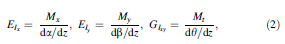
The blade rigidity is an important physical behavior used to characterize its performance and is defined by three components: edgewise (EIx ), flipwise (EIy ) and torsional (GIxy ) rigidity. These components are described by the relations given in Eq. (2).
 |
| Fig. 8 Dominant modes of frequency analysis response shapes |
The dynamic response in aerodynamic systems is usually not fully understood, and the complexity of understanding the wind turbine blade behavior is well-known and accepted. On the other hand, the computational tools developed through several research efforts establish a good starting point towards a better understanding of the aerodynamic behavior of turbine blade performance. At the same time, it will be necessary to carry out simulations that include reliable data using solvers that can handle highly complex environmental conditions of the location where these machines are installed. In this process, a robust aero elastic modeling of the blade that can serve as a design optimization tool is obtained. The robustness and minimal computing capacity requirements make the BEM model [16] to be most widely used in today's aeroelastic codes for modeling of the rotor aerodynamics. 3.3 MBD simulation of wind turbine transmission system
In the conversion process of wind energy into useful electrical energy, the transmission system plays an important role. This is because a large amount of energy is lost in the system due to inefficiencies caused by frictional losses and other mechanical interactions. The gearbox in the transmission system, in general, is commonly considered as the weakest link [17, 18] because it is exposed to highly dynamic and variable loads. In the current booming market of wind turbines, in particular, the design of reliable and cost effective subsystems is highly focused upon because the major part of downtime and loss of income are attributed to losses in this area. To develop better understanding of the complex interaction of the components, simulation-based research has been conducted on the gearbox of the wind turbine transmission system.
As an extension of other numerical computation based analysis and simulation, MBD modeling approach widely focuses on modeling and simulation of mechanism performance of complex mechanical systems. To address the progressive needs, several MBD simulation packages such as ADAMS are appearing in both academia and the industrial applications. Being an infant subject, application of MBD simulation in different areas still requires research.
One of the challenges in modeling the dynamic behavior of gearbox systems is provision of realistic data on the stiffness and damping properties of mechanical components, joints, and bearings. Tribological properties of bearing contacts and bearing stiffness are the primary modeling parameters of gearbox transmission [19] in order to predict failure, optimize design, evaluate noise, study structural integrity, etc. As a result, recent studies [20, 21, 22, 23] have focused on accurate modeling of the transmission, bearings and joints using MBD simulation. 4 Computational simulation of wave energy converters
Applications of numerical computation techniques highly contribute to better understand the performance of wave energy converters. In the process of studying the involved fluid-structure interactions, numerical simulation is generally considered as an important design optimization tool. The numerical models are developed using a variety of numerical techniques, including the FEM, the finite difference method, the boundary volume method, the boundary element method [24] and the MBD of the involved mechanisms.
In addition to improving the knowledge about the amount of energy transported along current speed, which varies depending on wave condition, computational techniques are enabled to deduce the dispersion of the currents and their transported hydrodynamic loads that are functions of the kinematics of the waves, the potential energy down to sea bead. To model the system, it is necessary to first understand the general principle of energy conversion, i.e., how the motion of an oscillating (rectilinear or angular) floating body is converted into the flow of a liquid at high pressure by using hydraulic systems. Figure 9 illustrates the important parameters that can be used in modeling and simulation of the energy carried by the moving wave.
 |
| Fig. 9 Modeling and simulation parameters of wave energy |
The WEC technology, in general, can be categorized into oscillating water columns (OWCs), oscillating bodies (such as point absorbers and bottom-hinged systems) and overtopping systems. Among these designs, the OWCs stand out as efficient, reliable and well-studied alternatives [25]. Figure 10 illustrates these categories with their respective possible application structures.
 |
| Fig. 10 Illustration of WEC device categories |
While the wave power of the oceans is widely accessible along the costs and in the large waters that cover the major part of the globe, study of simulation of wave energy converters using MBD simulation is not sufficiently covered in the literature. As reported by Babarit et al. [26], a possible reason may be lack of motivation and focus in this area, both from academia and industrial sector. Though the wave energy sector faces lack of research attention, the techniques of numerical computations in general can be adopted from modeling techniques of offshore structures by adopting the principle of inverse offshore engineering [27] where the point absorbers [28] and OWC-type wave energy converters [29, 30] are widely used.
The MBD simulation of such structures involves definition of each part as a system of multiple floating (or fixed) bodies linked by rigid or flexible constraints within the framework of potential flow theory [31]. The converters are modeled with respect to hydrodynamics and structural problems [32, 33] where boundary elements and FEA software such as WAMIT and ABAQUS [34] are used respectively.
The studies in general indicate that theoretical and analytical approaches are unable to provide sufficient characteristic performance of WECs. Employing numerical computation techniques, on the other hand, complex hydrodynamic models can be used within integrated CAD/ CAE environment since stand alone tools have limitations to better predict the device behavior, for instance in irregular waves. 5 Conclusions
This paper presented a brief overview of numerical computation methods for research in mechanical system simulation with due attention on energy conversion systems. The existing computational tools are highlighted through illustrative applications and the outstanding challenges are underlined. Primary focus is given on two computational tools, i.e., FEA and MBD simulation in wind and wave energy conversion because these devices are one of the most important renewable energy sources. The study indicates that computational techniques are key tools for economical and sustainable design and product development specially to virtually test complex systems that are not amenable for physical test and operation in harsh environment.
One of the main concerns for effective application of computational techniques in engineering is guaranteeing the result quality. This depends on understanding of the governing mechanics of the physical system and making appropriate choices of the simulation programs and solvers. Furthermore, establishing efficient communication among the modeling and simulation tools needs closer research. In MBD simulation, for instance, the core topics such as theoretical and computational methods for both rigid and flexible systems, multibody components involving large deformations are potential research areas of the future.
| 1. | Petrova R, Lemu HG, Larion I (2013) Study of horizontal axis wind turbine blade in virtual wind tunnel simulator. In: Proceedings of ASME 2013 international mechanical engineering congress and exposition (IMECE2013), 14-21 Nov 2013, San Diego, CA, USA |
| 2. | Milano F (2004) An open source power system analysis toolbox. IEEE Trans Power Syst 20:1199-1206 |
| 3. | Li W, Vanfretti L, Chompoobutrgool Y (2012) Development and implementation of hydro turbine and governor models in a free and open source software package. Simul Model Pract Theor24:84-102 |
| 4. | Cigel R et al (2011) Simulation data management—survey report, NAFEMS 2011 |
| 5. | Courant R (1943) Variational methods for the solution of problems of equilibrium and vibrations. Bull Am Math Soc 49:1-23 |
| 6. | Lemu HG (2013) Study of the role of virtual engineering technologies in design. In: Wang KS, Strandhagen JO, Tu DW (eds) Proceedings of international workshop of advanced manufacturing and automation (IWAMA 2013), Tapir Academic Press, Trondheim, No 4, pp 59-69 |
| 7. | Luo N, Pacheco L, Vidal Y, Li H (2012) Smart structural control strategies for offshore wind power generation with floating wind turbines. In: Proceedings of international conference on renewable energies & power quality journal, Santiago de Compostela, Spain |
| 8. | Lemu HG (2014) Virtual engineering in design and manufacturing. Adv Manuf 2:289-294 |
| 9. | Petrova R, Lemu HG (2014) Stress and displacement analysis of a HAWT under time-variable wind. In: ASME 2014, international mechanical engineering congress and exposition (IMECE2014), 14-20 Nov 2014, Montreal, Canada |
| 10. | Petrova R, Lemu HG (2012) Design study for dynamic behavior of wind turbine blade. In: Proceedings of international workshop of advanced manufacturing and automation (IWAMA 2012), Tapir Academic Press, Trondheim, pp 131-138 |
| 11. | Shienlen W (1997) Multibody dynamics: roots and perspectives. Multibody Syst Dyn 1:149-188 |
| 12. | Shen X, Zhu X, Du Z (2011) Wind turbine aerodynamics and loads control in wind shear flow. Energy 36(3):1424-1434 |
| 13. | Hansen MOL et al (2006) State of the art in wind turbine aerodynamics and aeroelasticity. Progress Aerosp Sci 42(4):285-330 |
| 14. | Lanzafame R, Messina M (2007) Fluid dynamics wind turbine design: critical analysis, optimization and application of BEM theory. Renew Energy 32(14):2291-2305 |
| 15. | Rajakumar S, Ravindran D (2012) Iterative approach for optimizing coefficient of power, coefficient of lift and drag of wind turbine rotor. Renew Energy 38:83-93 |
| 16. | Glauert H (1963) Airplane propellers. In: Durand WF (ed) Aerodynamic theory. Dover, New York, pp 182-269 |
| 17. | Manwell JF, McGrowan JG, Rogers AL (2009) Wind energy explained, theory, design and application. Wiley, Chichester |
| 18. | Helsen J, Vanhollebeke F et al (2011) Multibody modelling of varying complexity for modal behavior analysis of wind turbine gearboxes. Renew Energy 36:3098-3113 |
| 19. | Sarangi M, Majumdar B, Sekhar A (2004) Stiffness and damping characteristics of lubricated ball bearings considering the surface roughness effect. part 1: theoretical formulation. Proceedings of the Institution of Mechanical Engineers. Part J: J Eng Tribol218:529-538 |
| 20. | Tomulik P, Fraczek J (2011) Simulation of multibody systems with the use of coupling techniques: a case study. Multibody Syst Dyn 25:145-165 |
| 21. | Das M, Barut A, Madenci E (2010) Analysis of multibody systems experiencing large elastic deformations. Multibody Syst Dyn 23:1-31 |
| 22. | Wasfy TM, Noor AK (2003) Computational strategies for flexible multibody systems. Appl Mech Rev 56:553-613 |
| 23. | Hong D, Ren G (2011) A modelling of sliding joint on onedimensional flexible medium. Multibody Syst Dyn 26:91-106 |
| 24. | Finnegan W, Goggins J (2012) Numerical simulation of linear water waves and wave-structure interaction. Ocean Eng 43:23-31 |
| 25. | Nunes G, Valério D et al (2011) Modelling and control of a wave energy converter. Renew Energy 36:1913-1921 |
| 26. | Babarit A, Hals J et al (2012) Numerical benchmarking study of a selection of wave energy converters. Renew Energy 41:44-63 |
| 27. | Buchner B (2010) Model tests and simulations on a wave energy converter based on inverse offshore engineering. Offshore Technol Conf. doi:10.4043/20366-MS |
| 28. | Li Y, Yu YH (2012) A synthesis of numerical methods for modelling wave energy converter-point absorbers. Renew Sustain Energy Rev 16:4352-4364 |
| 29. | Nagata S, Toyota K et al (2009) Numerical simulation for evaluation of primary energy conversion of floating OWC-type wave energy converter. In: Proceedings of the International offshore and polar engineering conference, Osaka, Japan, pp 300-307 |
| 30. | Hong DC, Hong SY, Hong SW (2004) Numerical study on the reverse drift force of floating BBDB wave energy absorbers. Ocean Eng 31:1257-1294 |
| 31. | Sun L, Taylor RE, Choo YS (2012) Multibody dynamic analysis of float-over installations. Ocean Eng 51:1-15 |
| 32. | Taghipour R, Arswendy A et al (2008) Structural analysis of a multibody wave energy converter in the frequency domain by interfacing WAMIT and ABAQUS. In: Proceedings of the international conference on offshore mechanics and arctic engineering— OMAE, No 1, pp 867-880 |
| 33. | Park JC, Uno Y et al (2004) Numerical reproduction of fully nonlinear multi-directional waves by a viscous 3D numerical wave tank. Ocean Eng 31:1549-1565 |
| 34. | Nader JR, Zhu SP et al (2012) A finite element study of the efficiency of arrays of oscillating water column wave energy converters. Ocean Eng 43:72-81 |