 2015, Vol. 3
The article information
- Ke-Sheng Wang, Zhe Li, Jørgen Braaten, Quan Yu
- Interpretation and compensation of backlash error data in machine centers for intelligent predictive maintenance using ANNs
- Advances in Manufacturing, 2015, 3(2): 97-104
- http://dx.doi.org/10.1007/s40436-015-0107-4
-
Article history
- Received: 2015-03-24
- Accepted: 2015-04-15
- Published online: 2015-05-14


2 Key Laboratory of Intelligent Manufacturing and Robotics, Shanghai University, Shanghai, P. R. China
Monitoring, modelling and controlling backlash error of mechanical systems is a topic that has been well studied by many researchers [1, 2, 3, 4]. The motivation of this topic is due to the fact that the nonlinearities of backlash errors limit the performance of speed and position loop in industrial motion system [5]. With the fast development of modern manufacturing technology, not only the compensation but also the prediction of backlash error is a high priority for industries.
Many compensation methods have been proposed to mitigate the adverse effects caused by backlash that occurs when the direction is changed. These methods can be classified into mechanical-based compensation and controlbased compensation. Although mechanical-based methods can eliminate the nonlinear effects of backlash, the energy consumption, cost and the overall weight of the system are generally increased [6].
The control-based methods compensate the backlash nonlinearity through designing an appropriate control algorithm. For the backlash model with unknown parameters, the inverse model is widely used to handle backlash, since an inverse model can eliminate the nonlinearity of backlash by estimating the parameters online. However, the effectiveness of an inverse model largely depends on the accuracy of the backlash model. Without accurate prediction, it may not be possible to get satisfactory compensation [7].
In order to solve the compensation problem, this paper predicts backlash error using artificial neural networks (ANNs) for implementing a predictive maintenance (PdM) strategy in machine centers. The aim of PdM is to predict when an equipment failure might occur, and to prevent occurrence of the failures by performing required maintenance. The task of monitoring for future failure allows maintenance to be planned before the failure occurs. Ideally, PdM reduces the maintenance frequency to the lowest possible state, in order to eliminate unplanned reactive maintenance, such as corrective or preventive maintenance, without incurring costs associated with doing too much preventative maintenance.
Predicting failure can be done with many techniques. The chosen technique must be effective at predicting failure and also provide sufficient warning time. The techniques may include vibration analysis, oil analysis, thermal imaging, and equipment observation (visualized or audible). Choosing the correct technique for performing condition monitoring is an important consideration that is done in consultation with equipment manufacturers and/or condition monitoring experts.
When PdM is working effectively, maintenance is only performed on machines just before failure is likely to occur. This minimizes the operational and resource cost such as the time the equipment is being maintained, the production hours lost to maintenance, and the cost of spare parts and supplies.
The remaining part of the paper is organized as follows. Section 2 briefly presents the classification of maintenance strategy and explains why PdM strategy is so important for industries. Section 3 discusses the role and definition of backlash error in machine centers. Sections 4 and 5 present a measurement system for backlash error detection and amethod to calculate the backlash error, respectively. Section 6 describes the process of predicting backlash error based on ANNs.The conclusions and futurework are summarized in the last section of this paper. 2 Predictive maintenance strategy
Progress in maintenance strategy benefits from a long historical development. According to the European Standard, maintenance is defined as the combination of all technical, administrative and managerial actions during the life cycle of an item intended to retain it in, or restore it to, a state in which it can perform the required function [8]. 2.1 Classification
Figure 1 shows the classification of maintenance strategies divided into three classes as corrective maintenance (CM), preventive maintenance (PM), and PdM. CM is similar to repair work, which is undertaken after occurrence of an obvious failure or a breakdown. PM is carried out at predetermined intervals or according to pre-described criteria with the intention to reduce the probability of failure or the degradation of the function of a component. These two strategies are very well known in most industries. Recently, the concept of PdM strategy has attracted more attention as discussed in Ref. [9].
 |
| Fig. 1 Classification of maintenance strategies |
One of the most popular and modern maintenance policies is PdM, which is also known as condition-based maintenance [10]. PdM measures parameters in the condition of equipment carry out the appropriate tasks to optimize the service life of machines and processes without increasing the risk of failure [11]. Based on the approaches of measuring the symptom of failures, there are two groups of PdM: statistical-based PdM and condition-based PdM.
Comparing with other maintenance strategies, PdM has some advantages: equipment that requires maintenance is shut down only before imminent failure; reducing the total time spent maintaining equipment; reducing maintenance costs by avoiding catastrophic damage; increasing availability and reliability of machines; extending life of equipment and processes.
Some disadvantages of PdM are as following: (i) The cost of the equipment needed for condition monitoring is often high. (ii) The skill level and experience required to accurately interpret condition monitoring data is also high. (iii) These can mean that condition monitoring has a high upfront cost. Some companies engage condition monitoring contractors to minimize the upfront costs of a condition monitoring program.
Not all equipment have failures that may be more cost-effectively maintained using preventative maintenance or a run-to-failure maintenance strategy. Judgment should be exercised when deciding if PdM is the best for a particular machine. Techniques such as reliability centered maintenance (RCM) provide a systematic method for determining if PdM is a good choice as a maintenance strategy for the particular machine of interest.
When implementing PdM strategy, several key techniques including sensors and signal processing techniques, feature extraction techniques, fault diagnosis and prognosis techniques and maintenance optimization techniques should be taken into account.
In the backlash error compensation system, PdM is used primarily to predict the backlash error and then compensation is made according to the estimation. The backlash error in machine centers is discussed in detail in Sect. 3. 3 Backlash error in machine centers 3.1 Machine center
Vertical machine centers are high-precision machines often used for tight-tolerance milling and meeting the most exacting production needs, such as fine die and mould work. Generally, a vertical machine center includes multiple sub-systems that need to be monitored, as shown in Fig. 2, including server motor system, ball screw system, guide system, spindle system, tool magazine, hydraulic system, cooling system and lubrication system, respectively [12]. Typical monitoring tasks include machine measurement system monitoring, vibration analysis, oil analysis, cutting fluid analysis and energy consumption analysis.
 |
| Fig. 2 Components of a machine center |
This paper focuses on machine measurement system which monitors, detects and predicts machine failures. The machine condition can be acquired through monitoring the difference between normal and abnormal of the measurement systems, and then compensations can be made according to the monitoring to achieve higher precision. A systematic error correction and compensation in machine centers is important to enhance the manufacturing accuracy [13]. And backlash compensation is one of the most important part of the system. 3.2 Backlash error
In mechanical engineering, backlash, sometimes called lash or play, is clearance or lost motion in a mechanism caused by gaps between the parts. It can be defined as ‘‘the maximum distance or angle through which any part of a mechanical system may be moved in one direction without applying appreciable force or motion to the next part in mechanical sequence’’[14].
Backlash error can be computed by different methods, which are either time-costly (laser interferometry) or only yield the maximum value computed. The effects of backlash error on machine accuracy are not discussed in detail in Ref. [15]. This paper focuses on the effects of the backlash on the position accuracy of the machine centers and the backlash error in the production process.
As shown in Fig. 3, in the ball bearing there is a small gap between the ball screw and the table (ball nut). When the direction is reversed, the ball nut does not move until the gap is taken up in the opposite direction [16]. The distance the screw has to travel until the table moves is called the backlash error. The error is not only occurring in the ball nut, since the gearbox and motor have the same mechanical clearance when the direction of motion is reversed. In general, all loosely connected elements in the driving mechanism can influence the backlash error of the system.
 |
| Fig. 3 Backlash error between the table and ball screw |
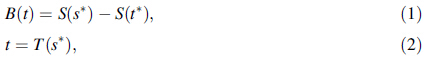
The backlash error varies at different axis positions and depends on the moving direction of the ball screw. The error affects the contouring accuracy and increases over time due to wear in the machine center. It is therefore important to monitor, model, predict and compensate the backlash error for maintaining the desired level of accuracy of the machine center [17]. The backlash calculation formulation can be described as
In order to measure the backlash error in a machine, the system requires two displacement measurements, i.e., the linear displacement of the ball screw and the linear displacement of the ball nut. The linear displacement of the ball screw is measured by the rotation angle of the ball screw with a rotary encoder in the motor and by converting the angle signal to linear displacement. To measure the displacement of the ball nut, a calibrated laser interferometer or linear scale encoder is normally used. These two measuring devices use laser-wavelength and optical grating along the axis to measure the displacement of the ball nut with a high accuracy.
The setup for measuring the backlash error is shown in Fig. 4. The rotary encoder measures the indirect position of the table, while the direct position of the table is measured by the linear scale. Backlash error is measured by calculating the difference between the rotary encoder x1 and the linear scale x2, when the motion of the table is reversed.
 |
| Fig. 4 Setup of backlash measurement |
A selection of 25 target positions in forward and backward directions respectively was measured in the test cycle, as show in Fig. 5. A closer look at the displacement plot in Fig. 6 indicates the possible target positions where the backlash error can be detected. Between 16.92 s and 17.10 s samples, the displacement moves forward to a target position. In addition, at around 17.58 s samples, the displacement begins to move in the backward direction. Then a backlash error of backward direction in -1 410 mm axis position occurs. Similarly, the next target point is in forward direction in -1 415 mm axis position, which occurs approximately at 18.30 s samples. But at 18.78 s samples, since the displacement moves in the same direction (forward), there is no backlash error in the area.
 |
| Fig. 5 Linear scale and rotary encoder displacement results |
 |
| Fig. 6 Displacement between 16.80 s and 19.20 s samples |
In order to acquire the accurate values in both forward and backward directions, the velocity n to be analyzed, as shown in Fig. 7. A closer look at the velocity plot in Fig. 8 indicates that the screw starts moving at 17.586 s samples while the table begins moving at 17.598 s samples. According to the definition of backlash, the distance between 17.586 s samples and 17.598 s samples in the displacement of screw is the backward backlash in -1 410 mm axis position.
 |
| Fig. 7 Displacement velocity of screw and table |
 |
| Fig. 8 Displacement velocity between 17.532 s and 17.604 s |
Then we can acquire the backlash error in both backward and forward directions, as shown in Fig. 9. In Fig. 9, we can find that the fluctuation of the backlash error in the same direction is within 1 lm.
 |
| Fig. 9 Backlash error in backward and forward direction |
ANNs are inspired by biological neural networks (the central nervous systems of animals, in particular the brain) and used to estimate or approximate functions that can depend on a large number of inputs [18].
In order to predict the nonlinear backlash error, the back-propagation (BP) ANN was used. BP is a learning method or a strategy for training the ANN. The standard BP (SBP) ANN is a standard supervised ANN. It is a kind of data-driven model, which can train the ANN model by the use of history data. SBP ANNs are used to generate models of systems, especially when the analytic approach is difficult to implemented. As shown in Fig. 10, the model generally has the architecture of one input and output layer, respectively, and at least one hidden layer, which are fully connected. The forward phase is the process evaluating the outputs according to inputs while the backward phase compares the outputs calculated in the forward phase with the target outputs and adjusts the weight of each link [19].
 |
| Fig. 10 Back-propagation neural network with a single hidden layer |
As shown in Fig. 11, the backlash error prediction process includes a training process and a prediction process. The neural network was trained in the training process, and the backlash can be predicted in the prediction process.
 |
| Fig. 11 Backlash error prediction process |
As shown in Figs. 12 and 13, the backward and forward backlash errorswere trained in SBPANN. The learning process can be divided into a training process and a testing process. In the training process, 70% of the experiment data were used to train and adjust the network according to the error between the target and output values. In the testing process, the remaining 30% data were divided into two groups: validation data and testing data. The validation group, which is 15% of the data is used to estimate the condition of the network’s generalization, which means the training will be halted if the generalization stops improving. The testing data have no effect on the training process, so an independent assessment can be made according to the testing results.
 |
| Fig. 12 Backward backlash error training results |
 |
| Fig. 13 Forward backlash error training results |
After the models have been developed, the backlash error can then be compensated. The whole procedure can be divided into three stages: backlash error calibration, backlash error modelling and training, and compensation. The error compensation is composed of the following steps:
(i) collecting the backlash error on nominal position of the axis at given position,
(ii) training the prediction model, (iii) calculating the errors between the commanded position and real position,
(iv) sending the compensation value to the machine centers to shift the origins of the slide axis to implement the error compensation.
The results of the position accuracy after backlash error compensation are shown in Figs. 14 and 15. According to the results, we can find that displacement error caused by backlash is in approximately 0.2 lm after compensation in both backward and forward directions.
 |
| Fig. 14 Backward backlash error compensation results |
 |
| Fig. 15 Forward backlash error compensation results |
The PdM strategy will play a very important role in future maintenance activities. This paper reports on research in the extraction and prediction of backlash error to realize thePdMin machine centers. We presented a method to analyze and measure the backlash error according to its mechanical characteristics. Finally, by using ANN model as the prediction model, the displacement error caused by backlash was in approximately 0.2 lm after compensation in both backward and forward directions. Further research can be done as following:
(i) The backlash error extracted in this paper still contains the mechanical error in the system, since there remains a little retard between the motion of screw and table even though no backlash exists. So future work may focus on the error separation.
(ii) The backlash error researched in this paper is considered stable in the experiment, which means that the prediction of backlash error is assumed independent of time. Further research will focus on the effect of time factor.
| 1. | Sander-Tavallaey S, Saarinen K (2009) Backlash identification in transmission unit. In: The 18th IEEE conference on control applications (CCA) & intelligent control, Saint Petersburg, Russia,8-10 July, 2009 |
| 2. | Ding BY, Cazzolato BS, Grainger S et al (2015) Active preload control of a redundantly actuated Stewart platform for backlash prevention. Robot Comput Integr Manuf 32:11-24 |
| 3. | Slamani M, Nubiola A, Bonev IA (2012) Modeling and assessment of the backlash error of an industrial robot. Robotica30:1167-1175 |
| 4. | Yoon SM, Choi WH, Lee MC (2014) Backlash compensation by smooth backlash inverse for haptic master device using cableconduit. In: The 14th international conference on control, automation and systems (ICCAS), Kintex, Korea, 22-25 October,2014 |
| 5. | Kolnik I, Agranovich G (2012) Backlash compensation for motion system with elastic transmission. In: IEEE 27th convention of electrical & electronics engineers in Israel (IEEEI), Eilat, Israel,14-17 November, 2012 |
| 6. | Han KH, Koh GO, Sung JM et al (2011) Adaptive control approach for improving control systems with unknown backlash. In: The 11th international conference on control, automation and systems (ICCAS), Gyeonggi-do, Korea, 26-29 October, 2011 |
| 7. | Ling Q, Yan Z, Shen HH et al (2014) Robust switching control strategy for a transmission system with unknown backlash. Math Probl Eng 2014:719384 |
| 8. | European Standard (2001) Maintenance terminology. European Committee for Standardization 13306, Brussels |
| 9. | Wang KS (2014) Key techniques in intelligent predictive maintenance (IPdM): a framework of intelligent fault diagnosis and prognosis system (IFDaPS). Adv Mater Res 1039:490-505. doi:10.4028/www.scienfific.net/AMR.1039.490 |
| 10. | Moya MCC (2004) The control of the setting up of a predictive maintenance programme using a system of indicators. Omega32(1):57-75 |
| 11. | Garcia MC, Sanz-Bobi MA, del Pico J (2006) SIMAP: intelligent system for predictive maintenance application to the health condition monitoring of a wind turbine gearbox. Comput Ind57(6):552-568 |
| 12. | Vachtsevanos G, Lewis FL, Roemer M et al (2006) Intelligent fault diagnosis and prognosis for engineering systems. Wiley, Hoboken |
| 13. | Khan AW, Chen WY (2011) A methodology for systematic geometric error compensation in five-axis machine tools. Int J Adv Manuf Technol 53(5-8):615-628 |
| 14. | Wightman EJ (1972) Instrumentation in process control. Butterworth- Heinemann, Oxford |
| 15. | Liu HL, Xue XN, Tan GY (2010) Backlash error measurement and compensation on the vertical machining center. Engineering2(6):403-407 |
| 16. | Youssef HA, El-Hofy H (2008) Machining technology: machine tools and operations. Chemical Rubber Company Press, London |
| 17. | Braaten J (2015) Data mining for intelligent green monitoring of machine centers. Dissertation, Norweigian University of Science and Technology |
| 18. | Siddique A, Yadava GS, Singh B (2003) Applications of artificial intelligence techniques for induction machine stator fault diagnostics: review. In: Proceedings of the IEEE international symposium on diagnostics for electric machines, power electronics and drives. IEEE, New York, pp 29-34 |
| 19. | Rao MA, Srinivas J (2003) Neural networks: algorithms and applications. Alpha Science International Ltd, Pangbourne |