 2015, Vol. 3
The article information
- R. Guerra Silva, U. Teicher, A. Nestler, A. Brosius
- Finite element modeling of chip separation in machining cellular metals
- Advances in Manufacturing, 2015, 3(1): 54-62
- http://dx.doi.org/10.1007/s40436-015-0099-0
-
Article history
- Received: 2014-06-12
- Accepted: 2015-01-06
- Published online: 2015-02-05


2. Institute of Manufacturing Technology, Dresden University of Technology, 01062 Dresden, Germany
Cellular metals are heterogeneous materials formed by a three-dimensional metallic matrix with gas-containing pores occupying more than 70% of their volume [1]. They are characterized by their advantageous combination of physical and mechanical properties,such as high stiffness combined with the very low specific weight. In recent years,there has been considerable interest in these materials,which has led to the development of new cellular materials and manufacturing techniques,as well as an evaluation of new fields of applications [1].
Although some components could be prepared in nearnet-shapes by some manufacturing methods [1],additional machining operations such as cutting or drilling are sometimes unavoidable. The conventional machining leads to a low surface quality and poor precision,and it is only practical for rough cutting [2]. Alternative methods that produce possible high-quality surfaces,such as electrodischarge machining (EDM) are preferred for finishing [2]. However,the conventional machining allows a higher productivity and lower cost,so it could be advantageous to expand its applicability through the reduction or elimination of the undesired effects. 2 Background 2.1 Machining of cellular metals
Machining tests have been carried out to determine the influences of the cutting parameters on the machinability of sintered cellular titanium [3, 4]. Lower cutting force, highly irregular machined surface with burrs and torn off of material were characteristics of the milling process. A reduction of the surface porosity and a shorter tool life were also reported. Similar results were obtained when milling cellular stainless steels [5]. Although these machining tests of cellular metals have offered some insights into the chip formation process in machining cellular metals,they are limited in scope. Moreover they are impractical due to the high manufacturing cost of the cellular metals and the large variability in measured properties [6]. 2.2 Chip formation mechanism in cellular metals
The discontinuous and continuous chips in machining nonmetallic cellular materials are recognizable [7, 8],but the chip formation mechanisms are essentially different to those observed in solid materials [4]. Hence,the classical models of chip formation,in which the formation of the chip is a result of the plastic deformation and subsequent separation of materials in the shear zone,cannot adequately describe the chip formation process in machining cellular metals [4]. Surface defects present in the machined surface of cellular metals,such as burrs and tearing off of material, are difficult to explain using this approach. The interrupted cut model [9] can explain the accelerated tool wear in porous materials,while it is still not capable of entirely describing the chip formation mechanism in the primary deformation zone [10]. Two possible mechanisms of chip formation in cellular metals based on the rake angle were proposed by Weinert et al. [4]. For positive rake angles,the material is torn out from the workpiece due to the low cohesive strength between sintered particles. This mechanism is similar to the chip formation in brittle materials (e.g.,cast steel). The machined surface is wavy and tearing off of material is visible. On the other hand,for tools with negative rake angle,the cell struts are plastically deformed and material is squeezed into the pores.
However,a relation between rake angle and surface damage could not be established when machining other cellular metals [5]. Both squeezing and tearing off of material were present for both negative and positive rake angles when machining cellular stainless steel. Since machining tests cannot entirely explain the chip formation mechanism,alternative experimental methods are required to analyze the chip formation process,such as the quick stop technique,cinephotomicrography and analytical models. Nevertheless,these methods are unsuitable for the analysis of chip formation in machining cellular metals [11]. The reasons are as follows: the quick stop technique is inadequate for timedependent processes; cinephotomicrography is only possible for low cutting speed (vc<1 m/min); an accurate prediction of cutting force is not possible using analytical methods.
An alternative to these methods is the finite element analysis. The finite element method provides detailed information on the stress,strain and temperature distribution as well as the interaction between chip and tool,thus enabling the analysis of the chip formation mechanism. The finite element method has been used to study the chip formation in homogeneous [12] and heterogeneous materials [13]. 2.3 Finite element modeling of cellular metals
The finite element models for cellular materials can be classified in three categories [1]: macroscopic (or equivalent homogeneous material (EHM)),micromechanic and embedded cell models. In this paper the term mesoscopic is used instead of micromechanic to differentiate between the microstructure (defined by grains and grain boundaries) and the structure of the cellular material (struts,walls and cells), which is normally in the range of 0.1-10 mm [14].
EHM models are used in the modeling of large components,i.e.,much larger than the cell size [1]. On the other hand,mesoscopic models take into consideration the mesostructure of the material. Struts,walls and cells are substituted by a simplified geometrical model that mimics the inner structure of the material. The length scale in machining is close to the cell size,thus a mesoscopic model is used in the present work for the simulation of the chip formation process. New mesoscopic models based on the computer tomography (CT) image reconstructions of cellular metals [15] have also been developed,but new problems must be addressed before any finite element simulation of machining processes is possible. 3 Material and methods
An open-cell cellular material made of a heat resistant austenitic stainless steel (EN 1.4841,45 ppi,cell size 1.1-1.3 mm,relative density ρr=0.077) was used as reference to create a finite element model (see Fig. 1). Its manufacturing process is based on the powder metallurgical replication technique [16].
 |
| Fig. 1 Measurement of strut thickness of the open-cell stainless steel |
The analyses of cell size and cell shape,strut thickness and cell patterns in the mesostructure of the material were carried out by Kalchunkova et al. [17]. It was observed that large cells appeared in clusters,while smaller cells were always surrounded by larger ones.
Based on this analysis a new mesoscopic model was developed. Straight struts with triangle-shaped vertices were the basic building blocks of the model. For the sake of simplicity,it is assumed that all struts are of the same average thickness (0.1 mm). Furthermore,mesoscopic defects such as missing or irregular struts,or filled pores were not included. Sharp edges were also rounded to avoid potential difficulties when modeling contact.
Four variants of the finite element model (A,B,C and D) are set up to take into consideration the variability in measured properties in cellular metals (see Fig. 2). Although a larger number of models are possible,only four are used to keep the number of simulations manageable. Cell size varies from 0.4 mm to 1.7 mm,with an average size of 1.0 mm. The ρr of the models is 0.170. By comparison the relative density of the sample is 0.077. When we are dealing with a two-dimensional (2D) representation of a three-dimensional (3D) structure,the conditions of relative density and cell arrangement cannot be satisfied simultaneously. For that reason only cell arrangement (cell size and strut thickness) was considered initially. The difference in relative density will be addressed using the scaling law in Section 4.
 |
| Fig. 2 Different cell arrangements in the finite element models a,b,c and d |
The optimal condition of the ‘‘surface’’,which is understood as a separation plane between the tool and the cellular material,is based on the material structure,as represented in Fig. 3. However,this cannot be easily described,and it is therefore the subject of current research [18]. Currently electro-discharge machined surface comes close to this ideal state without any tearing or smearing [1].
 |
| Fig. 3 2D model of cellular material (initial state and tool path for a depth of cut (h)=2 mm,b h=1 mm andcbest possible surface. The dashed linerepresents both tool path and the optimal cutting surface) |
The beam and shell finite elements provide an inexpensive solution for describing the mechanical behavior of open and closed-cell cellular metals,but they are still inadequate for modeling large deformations [19]. Instead,continuum elements were used to model the mesoscopic machining of cellular metals. Continuum elements allow very large local deformations and self-contact between struts/walls,which are necessary for modeling the inelastic behavior of cellular materials during machining. Coupled temperature-displacement,3-node linear,plane strain elements (CPE3T,Abaqus/Explicit) were used to discretize the model. The discretization of thin struts requires at least four continuum elements in their cross section [19]. An average of 22 720 elements and 13 770 nodes were used in each model.
The time step was automatically calculated and adjusted by the software Abaqus/Explicit. Mass scaling was required in order to accelerate convergence. A set of preliminary simulations were carried out using different mass scaling factors (100-10106) in order to find the optimal value. It was determined that convergence could be achieved with negligible effects on the results using a mass scaling factor of 104. 3.3 Constitutive equation
It is important to differentiate between the macroscopic mechanical properties of the cellular material and those of the material in cell walls and struts,i.e.,the basis material. The macroscopic mechanical properties could be measured using standard tests,which are widely available for several cellular metals,while the data of the mechanical properties of the material in the struts are scarce and difficult to obtain [15]. The mechanical properties of the material in struts can be determined through microindentation [20] and nanoindentation [21],but these methods only provide information at the very low strain rate.
An alternative approach to this problem is based on the use of the mechanical properties of the solid basis material plus an adjustment factor that considers the micropores and imperfections in the struts [22]. Nevertheless,the manufacturing process of the cellular metals involves metal powder techniques,so the mechanical properties in struts should be similar to those of sintered materials.
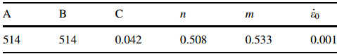
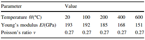
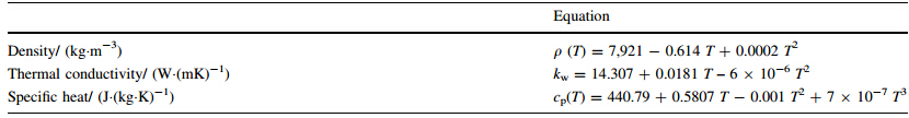
In order to determine the best approach,preliminary simulations for both sintered [23, 24] and solid AISI 316L [25] were carried out and compared. The mechanical properties of the stainless steel AISI 316L (EN 1.4404), were used instead of those of the stainless steel (EN 1.4841),because the latest mechanical behavior at high strain rates has not been characterized. The difference in the simulations was negligible. The Johnson-Cook model for solid AISI 316L was more efficient,as a result,the Johnson-Cook coefficients of solid stainless steel AISI 316L (see Table 1) were used. Additional mechanical and thermophysical properties required in the simulation reported in the literature were used (see Tables 2 and 3). The properties of solid stainless steel were used only when the properties of sintered steel were not available.
 |
Preliminary simulations were carried out using the progressive damage and failure model available in ABAQUS/ Explicit Version 6.9.3 [28]. Two damage initiation criteria were evaluated: ductile and shear. Furthermore,a sensibility analysis was carried out using the ductile criterion to determine the influence of the parameters in the analysis. It was determined that both damage model (i.e.,initiation criterion) and parameters had little influence on the results. The ductile damage model was used to model material separation during the machining simulation. Neither a separation line nor remeshing was necessary. The model was adapted to the sintered stainless steel AISI 316L using experimental data from Split Hopkinson Pressure Bar tests [23, 24]. 3.5 Friction
Research on contact mechanics of cellular materials has been limited [29, 30]. The Coulomb friction model,which was commonly used in machining simulations [31],was used in the present work. The penalty method is used to enforce the contact conditions at the tool-chip interface and also for the self-contact between struts. Two different values of friction coefficient (u =0.2 and 0.8) were evaluated to determine its influence on the simulation. 3.6 Boundary conditions
The workpiece in machining tests was fixed alongside the tool path (see Fig. 4a),however in the simulation only the lower and lateral surfaces of the workpiece were fixed (see Fig. 4b). In that way the rigidity of the structure is maintained while at the same time preserving the deformability of the inner struts. The 1 mm distance between fixture and tool observed in the machining test is preserved between tool path and the fixed nodes of the lateral surfaces in the simulation (see Fig. 4b). The tool is modeled as a rigid body with only one degree of freedom,i.e.,displacement in the x-axis.
 |
| Fig. 4 Boundary conditions for a orthogonal machining test and b the finite element simulation of the machining |
The initial temperature of the workpiece is the room temperature (θ0=25°C). The temperature of the tool remains constant during the simulation,and it is also identical to the room temperature. The Taylor-Quinney coefficient is set as 0.9. 4 Results 4.1 Validation
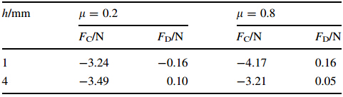
Experimental data of orthogonal machining tests were used to validate the finite element model. In the machining tests the cutting speed (νc=20 m/min),rake angle (γ0=40°) and workpiece width (b=4 mm) remained unchanged. Two different cases (h=1 mm and 4 mm) were simulated. Cutting and thrust forces were measured. The chip formation process was also recorded using a video camera. From a macroscopic point of view,the chip formation process in both simulation and test were similar (see Fig. 5). In both simulation and experiment an uneven surface was obtained and the damage was limited to a narrow area,about one cell size wide. The cutting force (Fc) and thrust force (FD) obtained in the finite element simulations are shown in Table 4. No clear connection between thrust force and friction coefficient could be established.
 |
| Fig. 5 Comparison of the chip formation process in finite element simulation and experiment (νc=20 m/min,h=4 mm) |
In order to compare the results of finite element simulation and machining tests,results were normalized by dividing the force components by the workpiece width

The difference in relative density must be considered, because the relative density of the finite element model (ρr=0.170) was greater than that of experimental samples (ρr=0.077).
The scaling laws [2] establish a relation between the mechanical properties and relative density in cellular materials. The scaling law for the compressive strength in open-cell materials is


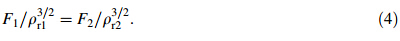
The scaled force components can be calculated from the normalized values

Table 5 shows the normalized and scaled values of the experimental and the calculated force components. The lower friction coefficient (μ=0.2) offered a good approximation for the cutting force. However,the numerical and experimental values of thrust force differ considerably. Whenlis equal to 0.8,the deviations that are equal to those of cutting force were larger,but the error is still under 15%. On the other hand,the error for the thrust force remains substantial.
 |
The thrust force is linked to both the chip separation and the compression of material ahead of the tool tip. In the experiments,the compressive action seems to be dominant whenhis equal to 1 mm,as the chip separation is considerably low. Conversely,whenhis equal to 4 mm,the chip separation becomes more relevant and the direction of the thrust force changes. On the other hand,the compression of material is the dominant factor in the finite element simulations,regardless of depth of cut (see Table 5). 4.2 Chip formation process
Further simulations were carried out for a higher cutting speed (νc=100 m/min),different rake angles (γ0=-10° and 20°) and depths of cut (h=1 mm and 2 mm) to analyze the chip formation mechanisms in cellular metals. Tool tip radius (0.05 mm) and relief angle (5°) remained unchanged,and their influence was not explored.
Two stages of the chip formation process are shown in Fig. 6(γ0=20°,νc=100 m/min,h=1 mm). As the tool penetrates into the workpiece,the cellular material is loaded to compression. This causes plastic deformation by bending and buckling of the struts in the region ahead of the cutting edge. After the first cells are crushed,part of the deformed struts squeeze under the cutting edge until they fracture under shear loading (see Fig. 6a). Afterwards,the cells in front of the cutting edge are crushed (see Fig. 6b). Some of these struts act as built-up edge. In the meantime, the struts below the cutting line are plastically deformed under tension,bending or a combination of both (see Fig. 6b).
 |
| Fig. 6 Two stages of the chip formation forγ0=20°,νc=100 m/min,h=1 mm (ModelA) |
When a negative rake angle is used (γ0=-10°),the struts below the entry point of the tool are loaded until bending or buckling begins (see Fig. 7a). Thereafter,these deformed struts are loaded under tension or shear until fracture occurs (see Fig. 7b). As in the previous case the material separation is caused by shear failure in the nodes located under the cutting edge (see Fig. 7b). This deformation process produces burrs and squeezing of material.
 |
| Fig. 7 Two stages of chip formation forγ0=-10°,νc=100 m/min,h=2 mm (ModelA) |
In Fig. 8,the results of the four models (A,B,C and D) when νc=100 m/min,h=1 mm,for both positive and negative rake angles are presented. The dashed line represents the ideal surface,which can be obtained using EDM. With a positive rake angle,the tearing off of material is visible (see Fig. 8,the first row). On the other hand,with a negative rake angle the first and second rows of cells are compacted,resulting in the densification of material and the fracture of struts (see Fig. 8,the second row). Squeezing of material is also evident. These results tearing off of material for positive rake angles and squeezing for negative rake angles—confirm the chip formation model proposed by Weinert et al. [4].
 |
| Fig. 8 Machined surfaces at the various models forνc=100 m/min,h=1 mm (the first row:γ0=20°; the second row: γ0=-10°) |
On the other hand,forh=2 mm the effect of the rake angle on the formation of surface defects is not clear-cut (see Fig. 9). Although squeezed material happens predominantly for a negative rake angle,tearing off of material is visible for both negative and positive rake angles,a deviation from Weinert’s model. Tearing off of material in models A,C and D is present for both positive and negative rake angles. This suggests that the mesostructure,i.e.,cell arrangement,plays a role in the formation of surface imperfections. On the other hand,the influence of the rake angle on the deformation of cells below the cutting surface is evident. A positive rake angle reduces the number of deformed cells. Alternatively,a negative rake angle results in a wider plastically deformed region.
 |
| Fig. 9 Machined surfaces at the various models forνc=100 m/min,h=2 mm (the first row:γ0=20°; the second row: γ0=-10°) |
The heterogeneous structure of the cellular material prevents the formation of a shear plane or stable secondary deformation zones near the rake surface,the machined surface or around the cutting edge. In a sense,the chip formation in cellular metals can be compared to that in fragile materials such as cast iron,in which the material is not separated but torn off from the workpiece. However,in fragile materials the discontinuous chip is formed with almost no plastic deformation,while in cellular metals the struts suffer a large amount of plastic deformation before they fracture. Thus,the machined surface is not only damaged through the tearing off of material,but also through the plastic deformation that enables the formation of burrs and squeezing. Furthermore,the stochastic cell arrangement,i.e.,mesostructure of the cellular metal is a decisive factor in the formation of surface defects,while the influence of the rake angle is not as clear-cut as suggested by Weinert et al. [4].
The deviation when comparing results and tendencies in numerical and experimental results could be attributed to two possible sources. The first one is the deviation between the mechanical properties of the basis material used in the finite element model and those of the actual basis material in experimental samples. The molybdenum contained in the stainless steel EN 1.4404 improves the ductility,while the silicon in the EN 1.4841 reduces it. A higher brittleness in the basis material should lead to a reduced elongation and lower tension strength in struts.
Other possible source of error is the difference between the finite element model and the actual experimental samples. The finite element model is a 2D structure,closer to a honeycomb than to the real 3D cellular material. For instance,in the real structure the struts in the cross-section are often missing (see Fig. 10), while in the finite element model they are not. Furthermore,the model does not consider the presence of mesoscopic irregularities (wavy struts,filled pores,variable strut thickness) and microscopic defects (microporosities and microcracks),which play an important role in the fracture of cellular materials [1]. Regarding the finite element simulation,two aspects should be brought to attention. Firstly,the influence of the friction coefficient on force components is difficult to ascertain. Although a lower friction coefficient improves the accuracy of the cutting force,there is no relation between the thrust force and the friction coefficient. Secondly,because finite element simulations using negative rake angle tools involve deformation in a larger number of cells,the simulation of contact becomes much more difficult than simulations with a positive rake angle. These difficulties cause numerical problems that lead to a premature ending of the simulation. A similar problem has also been observed when using a larger depth of cut.
 |
| Fig. 10 Cross section of the open-cell cellular stainless steel [18] |
A 2D mesoscopic finite element model to analyze the chip formation process in cellular metals is presented. Possible chip formation mechanisms in the machining of cellular materials are discussed. Although bending and buckling play a role in the initial stages,material separation occurs firstly through tension loading of struts and finally through shear loading near the nodes.
An analysis of surface damage shows that the squeezing and tearing off of material do not depend exclusively on the rake angle,which contradicts a previous surface damage model. At lower cutting speeds material squeezing occurs mainly for a negative rake angle,variations in depth of cut also influence the surface damage. Furthermore,the stochastic cell arrangement is a decisive factor in the chip formation process. A prediction of the cutting force using the finite element model is possible,but the results for thrust force deviate considerably from the experimental values. On the other hand,it is possible to model the chip formation process and the mechanisms. Future articles using the mesoscopic finite element model will address the influence of the cutting parameter and tool geometry on the chip formation process,as well as some ideas to improve the machining of cellular metals.
Acknowledgments We would like to thank the DAAD-Fundayacucho Scholarship Program and the Center for Information Services and High Performance Computing of the TU Dresden for their support. We would also like to thanks Peter Quadbeck of the Fraunhofer Institute for Manufacturing Technology and Advanced Materials, Branch Lab Dresden for providing the samples of material used in the experiments and Mr. Bernd Nipl for the support during the experiments.| 1. | Degischer HP, Kriszt B (2002) Handbook of cellular metals: production, processing, applications. Wiley-VCH, Weinheim |
| 2. | Ashby MF, Evans AG, Fleck NA et al (2000) Metal foams: a design guide. Butterworth-Heinemann, Massachusetts |
| 3. | Bram M, Kempmann C, Laptev A et al (2003) Investigations on the machining of sintered titanium foams utilizing face milling and peripheral grinding. Adv Eng Mater 5:441-447 |
| 4. | Weinert K, Bram M, Kempmann C et al (2003) Machinability investigations concerning the milling and grinding of metal foams. Prod Eng 2:65-70 |
| 5. | Teicher U, Künanz K, Nestler A (2009) Milling of open-cell metal foams. In: Proceedings of the 6th international conference on porous metals and metallic foams. Bratislava, Slovakia, 1-4 Sept 2009 |
| 6. | Ramamurty U, Paul A (2004) Variability in mechanical properties of a metal foam. Acta Mater 52:869-876 |
| 7. | Malak SFF, Anderson IA (2005) Orthogonal cutting of polyurethane foam. Int J Mech Sci 47:867-883 |
| 8. | Malak SFF, Anderson IA (2008) Orthogonal cutting of cancellous bone with application to the harvesting of bone autograft. Med Eng Phys 30:717-724 |
| 9. | Ogata Y, Shirashi J, Nakai T (2000) Various PM parts machinability using cutting tools. In: Proceedings of powder metallurgy world congress 12-16 Nov 2000, 1578-1582 |
| 10. | Šalak A, Selecká M, Danninger H (2005) Machinability of powder metallurgy steels. Cambridge International Science Publishing, Cambridge |
| 11. | Denkena B, Tönshoff H (2004) Spanen—Grundlagen. Springer, Berlin |
| 12. | Mackerle J (2002) Finite element analysis and simulation of machining: an addendum: a bibliography (1996-2002). Int J Mach Tool Manuf 43:103-114 |
| 13. | Davim J (2011) Machining of metal matrix composites. Springer, London |
| 14. | Banhart J (2001) Manufacture, characterisation and application of cellular metals and metal foams. Prog Mater Sci 46:559-632 |
| 15. | Jeon I, Katou K, Sonoda T et al (2009) Cell wall mechanical properties of closed-cell Al foam. Mech Mater 41:60-73 |
| 16. | Stephani G, Andersen O, Göhler H et al (2006) Iron based cellular structures—status and prospects. Adv Eng Mater 8:847-852 |
| 17. | Kalchunkova N, Guerra R, Teicher U et al (2010) Numerical models of metal foams for the simulation of machining. In: Proceddings of the 8th European conference on foams and applications. Borovets, Bulgaria, 14-16 July 2010 |
| 18. | Teicher U, Nestler A (2013) A method to simulate structural properties of cellular materials for machining processes. Procedia CIRP 8:100-104 |
| 19. | Hönig A, Stronge W (2002) In-plane dynamic crushing of honeycomb. Part II: application to impact. Int J Mech Sci 44:1697-1714 |
| 20. | Kim A, Tunvir K (2006) Study of Al-alloy foam compressive behavior based on instrumented sharp indentation technology. J Mech Sci Technol 20:819-827 |
| 21. | Hasan M, Kim A, Lee H (2008) Measuring the cell wall mechanical properties of Al alloy foams using the nanoindentation method. Compos Struct 83:180-188 |
| 22. | Caty O, Maire E, Youssef S et al (2008) Modeling the properties of closed-cell cellular materials from tomography images using finite shell elements. Acta Mater 56:5524-5534 |
| 23. | Lee WS, Lin CF, Liu TJ (2006) Strain rate dependence of impact properties of sintered 316L stainless steel. J Nucl Mater 359:247-257 |
| 24. | Lee WS, Lin CF, Liu TJ (2007) Impact and fracture response of sintered 316L stainless steel subjected to high strain rate loading. Mater Charact 58:363-370 |
| 25. | Tounsi N, Vincenti J, Otho A et al (2002) From the basics of orthogonal metal cutting toward the identification of the constitutive equation. Int J Mach Tool Manuf 42:1373-1383 |
| 26. | ASM International Handbook Committee (1998) ASM handbook Vol. 7: powder metal technologies and applications. ASM International, Materials Park |
| 27. | Umbrello D, M'Saoubi R, Outeiro JC (2007) The influence of Johnson-Cook material constants on finite element simulation of machining of AISI 316L steel. Int J Mach Tool Manuf 47:462-470 |
| 28. | Dassault Systèmes Simulia Corp (2009) ABAQUS User's manuals, Version 6.9, Providence, Dassault Systèmes Simulia Corp |
| 29. | Fortes M, Colaço R, Vaz F (1999) The contact mechanics of cellular solids. Wear 230:1-10 |
| 30. | Guerra R, Teicher U, Nestler A et al (2015) Influence of material and constitutive models on friction analysis for modelling in machining cellular metal structures. Appl Mech Mater 727-728:292-298 |
| 31. | Bil H, Kılıç SE, Tekkaya AE (2004) A comparison of orthogonal cutting data from experiments with three different finite element models. Int J Mach Tool Manuf 44:933-944 |