 2023, Vol. 34


b College of Chemistry and Molecular Sciences, Hubei Key Laboratory of Electrochemical Power Sources, Wuhan University, Wuhan 430072, China
Rechargeable LIBs with high energy and power densities have attracted great attention at fundamental application in that they are regarded as an alternative energy technology to alleviate the critical concerns of an escalating energy crisis and environmental pollution [1,2]. To date, graphite is the most successful and well-established commercial anode material for LIBs, which is widely explored over the past decades. However, conventional graphite electrode material suffers from relatively low theoretical specific capacity (372 mA/g), unsatisfactory rate capability as well as poor electrode durability in large-scale electrochemical storage [3]. Accordingly, significant efforts have been devoted to searching for new-type carbon materials with high specific capacity, superior rate performance and durability that are suitable for alternatives to commercial graphite [4,5]. Numerous carbonaceous anode materials, including graphene, carbon nanotubes, carbon nanofibers and porous carbon materials, have been extensively investigated [3,6-8]. Among them, porous carbon materials with high specific surface areas and open pore nanostructures are of particular interests for enhancing Li+ storage capacity, as they are not only enlarge the electrode/electrolyte interface to shorten Li+ transfer length and simultaneously enhance the charge-transfer reaction, but also provide abundant defects that can act as storage sites for Li+ [3,9-12].
To further improve the LIBs performances of a variety of porous carbon materials, heteroatom-doped strategies, containing B, N, S, P and halogen atoms, have being proposed [13-18]. The embedment of heteroatom into carbon frameworks, on the one hand, is capable of enhancing electronic properties to accelerate the electron transport and simultaneously inducing the formation of abundant defects in carbon skeleton to provide more active sites for ion storage [19]. On the other hand, the heteroatom incorporated into carbon layers in carbon materials inevitably enlarge the d002-spacing of graphite layers, thus providing sufficient space for ultrafast Li+ intercalation/deintercalation [20,21]. Sulfur atom with larger atom size is beneficial for expanding lattice spacing of carbon layer compared to nitrogen [15,20]. Lu et al. reported a sulfur‑doped porous carbon prepared by an in-situ templating approach, which showed excellent performances for LIBs (943 mAh/g at 0.05 A/g) [22]. The heteroatom-doped carbon materials need to be treated at harsh conditions (such as KOH activation) to increase their specific surface area, but normally form micropores [3,23,24]. And some of micropores were initially blocked or damaged during the electrochemical measurements, which adversely affects the ion accessibility and cycling stability [24]. Therefore, the mesopore channels in porous carbon at high current density are more favorable for the mass transfer in comparison to micropores. Furthermore, hollow structures in carbon materials also provide facile ion channels and withstand large volume expansion during cycling. Therefore, heteroatom-doped mesoporous carbon materials with hollow structures, uniform pore size and ultrahigh surface areas are highly desirable but remain a huge challenge.
We herein report the preparation of sulfur-doped hollow-structured mesoporous carbon (CMK-5-S) by using surface modified mesoporous silica SBA-15 as a hard template, and 2-thiophenemethanol (TPM) as a carbon precursor. The obtained CMK-5-S with hollow structures analogous to that of CMK-5 displays very high specific surface area (1390 m2/g), large pore volume (1.8 cm3/g), bimodal distributions (2.9 and 4.6 nm), and high sulfur content (2.5 at%). As a potential anode for LIBs, the CMK-5-S exhibits an excellent Li+ storage capacity (a reversible specific capacity of 1580 mAh/g at 0.1 A/g) and cycling performance (701 mAh/g after 500 cycles at 1 A/g) compared to the reference electrodes. Such excellent performances of CMK-5-S are associated with its peculiar hollow mesostructure as well as the heteroatom-doped effect. Furthermore, we envision that such a heteroatom-doped mesoporous carbon with hollow mesostructure is likely to have great potential for supercapacitor, adsorbent, catalysts, and catalyst supports.
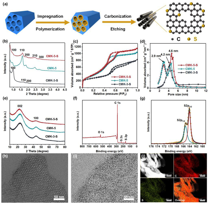
Fig. 1a illustrates the schematic representation of the preparation process of CMK-5-S. A surface modified SBA-15 rich-in silanol groups [25] was used as the hard-template, and TPM with containing sulfur element was selected as the carbon precursor, see experimental section. For comparison, the undoped hollow mesostructured carbon material (CMK-5) and the sulfur-doped solid mesostructured carbon material (CMK-3-S) were synthesized. The low-angle XRD (LAXRD) patterns of CMK-5-S (Fig. 1b) exhibits five well-resolved reflection peaks, which can be indexed to (100), (110), (200), (210) and (300) reflections of p6mm symmetry, confirming a good replication of the mesostructure of SBA-15. The lower intensity of (100) peak than that of (110) implies a CMK-5-like feature with bundles of carbon nanopipes [26-28]. Nitrogen adsorption–desorption isotherms of CMK-5-S and CMK-5 (Fig. 1c) exhibit characteristic type Ⅳ curves featured with a distinct capillary condensation step at P/P0 = 0.40–0.65, suggesting the obtained mesoporous carbon materials exist mesoporosity. The corresponding pore size distribution curves (Fig. 1d) of both CMK-5-S and CMK-5 display two sets of pores with a bimodal maximum pore size at about 2.9 and 4.6 nm. The 2.9 nm one can be assigned to the mesopore formed by the removal of silica template, which matches with the pore wall thickness of SBA-15. While the 4.6 nm one is derived from the inner pores of carbon nanopipes. These results indicate that the CMK-5-S has a hollow-structured mesostructure similar to that of CMK-5 [27,28]. In contrast, the pore size distribution curve of CMK-3-S only shows a sharp maximum peak at approximately 4.2 nm. The specific surface area of CMK-5-S estimated by BET method is up to 1390 m2/g, which is much higher than that of CMK-3-S with solid nanorod arrays (990 m2/g). Notably, S-doped mesoporous carbon CMK-5-S owns a higher pore volume (1.80 cm3/g) as compared to the S-doped CMK-3-S with solid nanorod arrays (Table S1 in Supporting information).

|
Download:
|
| Fig. 1. (a) Schematic illustration of the synthesis procedure for CMK-5-S. (b) Low-angle XRD patterns, (c) nitrogen adsorption–desorption isothermals, (d) corresponding pore size distribution curves, and (e) wide-angle XRD patterns of CMK-5-S, CMK-3-S and CMK-5. (f) XPS full-scan and (g) high-resolution S 2p spectrum of CMK-5-S. (h, i) TEM images and (j) STEM image, carbon and sulfur elemental mappings of CMK-5-S. | |
Wide-angle XRD (WAXRD) patterns (Fig. 1e) of all the three samples show two very apparent diffraction peaks centered at about 23° and 43°, corresponding to (002) and (100) planes of the amorphous carbon materials. This result also verifies the amorphous nature of carbon material, which can be confirmed by the Raman spectra (Fig. S1 in Supporting information). Interestingly, the (002) diffraction peaks of CMK-3-S and CMK-5-S are shifted to 23.0° and 22.5°, respectively when compared to that of pure carbon-based CMK-5 (23.5°), suggesting an expanded interlayer distance of (002) plane. These phenomena can be explained by the doping of bigger atom sulfur that expand the layer of graphite crystallites [29,30]. The expanded d-spacing of (002) crystal plane is beneficial to provide larger space for the electrochemical storage, such as accommodating more lithium ions and accelerating their diffusion simultaneously [31,32].
X-ray photoelectron spectroscopy (XPS) was employed to detect the chemical status of the sulfur element on the surface of CMK-5-S and CMK-3-S. The full-scan XPS spectra (Fig. 1f and Fig. S2a in Supporting information) exhibit four distinct peaks centered at approximately 164.1, 228.2, 284.6 and 532.7 eV, which can be assigned to S 2p, S 2s, C 1s and O 1s signals [33]. The sulfur contents of CMK-5-S and CMK-3-S determined by XPS are 2.5 at% and 2.0 at%, respectively. Furthermore, the characteristic signals of Fe and Cl element were not detected (Fig. 1f), indicating that the contents of Fe and Cl may be too low to be detected. The Fe content measured by ICP-AES is as low as 0.15 wt%, further demonstrating the efficiently removal of Fe species. The high-resolution S 2p XPS spectrum of CMK-5-S (Fig. 1g) can be deconvoluted into two peaks centered at 163.8 and 164.9 eV, which are assigned to S 2p3/2 and S 2p1/2 in the configuration of carbon-sulfur-carbon [20]. For CMK-3-S sample, a new deconvoluted peak appeared at 169.2 eV (Fig. S2b in Supporting information), which can be assigned to the oxidized sulfur [33,34]. These observations above suggest that the S element has been introduced into the framework of mesoporous carbon with doped status, and the sulfur atoms may bond to carbon atoms by covalent bonds.
Scanning electron microscopy (SEM) and transmission electron microscopy (TEM) methods were used for confirm the morphology and microstructure of the CMK-5-S. The low-magnification SEM image (Fig. S3a in Supporting information) of CMK-5-S shows a rod-like morphology analogous to that of SBA-15 template, indicating a perfect replication of the parent template [20]. The high-resolution SEM (HR-SEM) image of CMK-5-S (Fig. S3b in Supporting information) confirms the formation of hollow carbon nanopipe structure with periodically packed bundle. The TEM image (Fig. 1h) taken from a microtome silice of the CMK-5-S exhibits hexagonally packed nanorings with an inner ring diameter of around 4.6 nm. TEM image (Fig. 1i) also further confirms the formation of tubular structure. Thus, the above SEM and TEM results reveal the obtained CMK-5-S owns a hollow mesostructure, which is consistent with the pore size distribution plots and the LAXRD measurements. Likewise, SEM (Fig. S4a in Supporting information) and TEM (Fig. S4b in Supporting information) images of CMK-5 also show a similar structure with the CMK-5-S material. Comparatively, the SEM and TEM images of CMK-3-S (Figs. S5a and b in Supporting information) display a hexagonally arranged nanorods, which resembles traditional mesoporous carbon [35]. High-resolution TEM (HR-TEM) image of CMK-5-S (Fig. S3c in Supporting information) shows fingerprint-like structure of curved graphitic carbon layers, which suggest a glassy carbon nature of the framework. Scanning transmission electron microscopy energy dispersive spectroscopy (STEM-EDS) elemental mappings of CMK-5-S (Fig. 1j) reveal the homogenously distribution of sulfur atom in the carbon framework. Similarly, the elemental mappings of the CMK-3-S (Figs. S5c-f in Supporting information) show a similar result.
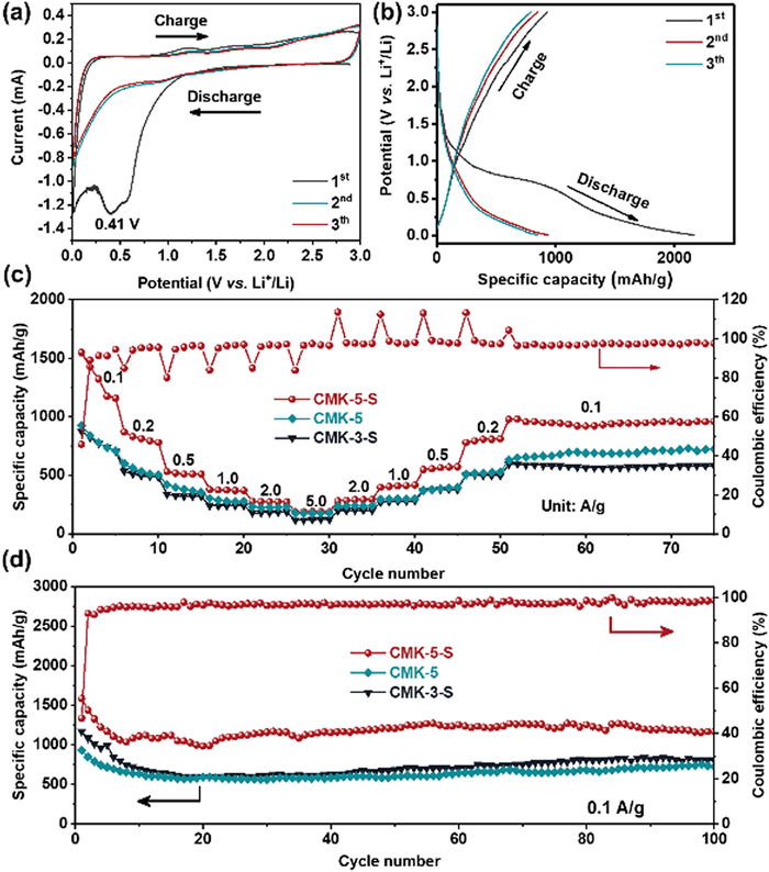
The electrochemical performances of CMK-5-S, CMK-3-S and CMK-5 were tested. Cycling voltammetry (CV) profile (Fig. 2a) of CMK-5-S at the first cycle appears a prominent reduction peak at approximately 0.41 V, which may be related to the electrolyte decomposition and the formation of the solid electrolyte interface (SEI) film [36,37]. The CV curves of CMK-5-S are almost overlapped in the following cycles, revealing an excellent cycling stability. Additionally, the reduction peak was detected at near 0 V, corresponding to the insertion of Li-ion into the carbon material [38,39]. The galvanostatic discharge-charge curves of the three samples were tested at a constant current density of 0.1 A/g, the results were shown in Fig. 2b and Fig. S6 (Supporting information). The first discharge and charge profiles of CMK-5-S display high specific capacities of 3389 and 1584 mAh/g, respectively. The initial Coulombic efficiency (ICE) is only 46.7%, which is slightly higher than that of mesoporous carbon CMK-5 (ICE = 43.0%). The low ICEs of CMK-5-S and CMK-5 are ascribed to their high specific surface areas, which can be potentially improved by additives in the electrolyte or using pre-lithium technology [40]. In addition, the electrode materials with different structures and morphologies are also profound influenced the electrochemical performances. Therefore, CMK-3-S with nanorod arrays was also used as an electrode material. Intriguingly, the specific capacities of CMK-3-S is only 2262 mAh/g for discharge and 1168 mAh/g for charge, respectively. This result suggests the specific surface area and/or the nanostructure have great influence on the Li ion storage performance. Large specific surface area and the thin shells reduce the ion diffusion in the solid phase, thus enhancing the LIB performance [41]. The rate capabilities and cycling performances of CMK-5-S and reference samples (CMK-5 and CMK-3-S) at various current densities are shown in Fig. 2c. At current densities of 0.1, 0.2, 0.5, 1.0 and 2.0 A/g, the reversible specific capacities of S-doped CMK-5-S were 1552, 870, 532, 376 and 284 mAh/g. When the current density was restored to the initial value of 0.1 A/g, the specific capacity rapidly recovered to 976 mAh/g. Moreover, reference samples exhibit lower specific capacities at the identical current densities (Table S2 in Supporting information). The excellent rate capabilities of CMK-5-S are not only associated with sulfur-doping that enhanced the capacity of electrochemical storage devices, but also influenced by the hollow structures that accommodate the strain relaxation and avoid interlayer slipping to ensure the structure integrity [22,42].

|
Download:
|
| Fig. 2. Electrochemical performances of CMK-5-S and its counterparts for LIBs. (a) CV curves and (b) the discharge-charge profiles of the first three-cycles for CMK-5-S electrode. (c) Rate capabilities and (d) cycling performances of CMK-5-S, CMK-3-S and CMK-5 at 0.1 A/g. | |
The cycling performances of these electrode materials were also investigated at the current density of 0.1, 1.0 and 5.0 A/g, as depicted in Fig. 2d and Fig. S7 (Supporting information). For CMK-5-S electrode, an initial charge specific capacity of 1584 mAh/g at a current density of 0.1 A/g was obtained. And the specific capacity of 1169 mAh/g after 100 cycles can be maintained, suggesting extraordinarily stable electrochemical performance. In contrast, CMK-3-S and CMK-5 exhibit inferior specific capacity of 804 and 730 mAh/g, respectively. Meanwhile, the specific capacity of other carbonaceous materials was listed in Table S3 (Supporting information). The Coulombic efficiencies of CMK-5-S remained greater than 98% during the cycling tests, indicating highly reversible property for efficient Li-ion insertion/extraction. When the current density reaches to 1.0 and 5.0 A/g, CMK-5-S delivers a high charge specific capacity of 701 and 298 mAh/g after 500 and 2000 cycles, respectively (Fig. S7 in Supporting information). It is noted that the specific capacity during cycling at 1.0 A/g increases significantly, which is ascribed to the activation of electrode during testing [3]. In contrast, CMK-5 exhibits the charge specific capacities of 382 and 203 mAh/g at the current density of 1.0 and 5.0 A/g after 500 and 2000 cycles, respectively. For CMK-3-S electrode, the charge specific capacities of 340 and 150 mAh/g were obtained. The significant cycling differences between the above electrodes imply that such excellent performances of CMK-5-S are mainly due to its peculiar hollow structures as well as sulfur-doping effect.
To elucidate the excellent stability of CMK-5-S, ex-situ SEM and TEM measurements were performed. The SEM (Fig. S8a in Supporting information) and TEM (Fig. S8b in Supporting information) images of CMK-5-S with hollow structures still display a rod-like morphology after 100 cycling tests at a current density of 0.1 A/g. All these results further prove that the CMK-5-S electrode owns good mechanical stability. Subsequently, ex-situ XPS and scanning electron microscopy energy dispersive spectroscopy (SEM-EDS) measurements of CMK-5-S were carried out to track the changes of sulfur species and contents. Compared to the initial CMK-5-S, the ex-situ XPS spectrum (Fig. S8c in Supporting information) of CMK-5-S shows the binding energy of S 2p3/2 and S 2p1/2 at the fully discharged state was negatively shift to 163.0 and 164.0 eV, indicating the existence of strong interaction between sulfur atoms and Li+ [43,44]. And these deconvoluted peaks located at 166.9, 168.9 and 169.6 eV can be assigned to the SOx species, demonstrating that sulfur atom in CMK-5-S was involved in the formation of SEI film [43,44]. When CMK-5-S electrode was recharged to 3.0 V, the binding energy of S 2p3/2 and S 2p1/2 was positively shifted to 163.2 and 164.1 eV (Fig. S8d in Supporting information), which are still lower than that of initial CMK-5-S. Notably, the characteristic binding energy peaks located at 166.9, 168.9 and 169.6 eV are not changed, indicating the irreversibility of these species exists [43]. And sulfur contents of CMK-5-S at 0.1 A/g after 0, 3, 10 and 30 cycles are summarized in Table S4 (Supporting information).
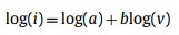
To further understand the kinetics of CMK-5-S, a series of CV profiles (Fig. 3a) were measured at different scanning rates from 0.2 mV/s to 1.2 mV/s between 0.01 V and 3.0 V. It is well accepted that the area surrounded by CV curves represents the total amount of LIBs capacity in the electrochemical reaction, that is, capacitive and diffusion contribution. The percentage of pseudocapacitive contribution ratio of the capacitive- and diffusion-controlled charge versus at different scan rates is calculated by the following equation [20,45].

|
(1) |
|
(2) |

|
Download:
|
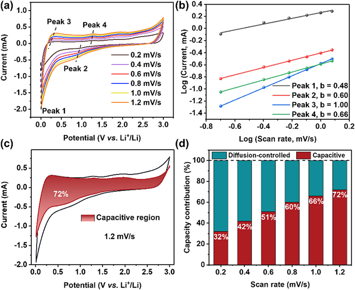
| Fig. 3. Kinetic properties of the CMK-5-S electrode. (a) CV curves at different scan rates. (b) Corresponding peak current versus square root of the scan rates. (c) CV profile with the capacitive contribution at a scan rate of 1.2 mV/s. (d) The percentage of pseudocapacitive contribution at different scan rates. | |
When the b-value approaches to 1.0, a capacitive-controlled process dominates in the storage behavior [20,46]. For b = 0.5, the current is dominated by diffusion-controlled behavior, suggesting a typical Faradaic reaction [41]. Interestingly, the b-value of peak 1 at 0.01 V is close to 0.5 (Fig. 3b), which is indicative of diffusion-controlled Faradaic behavior. On the other hand, the b-value of peak 3 can be determined as 1.0, demonstrating that the mechanism of Li+ storage in CMK-5-S is capacitive-controlled behaviors. However, the b-values of peak 2 and peak 4 are 0.60 and 0.66, respectively, suggesting that the Li+ storage in CMK-5-S anode material at above two potentials are controlled by both the diffusion- and capacitive-controlled process. To further quantify the capacitive and diffusion contribution in CMK-5-S anode material, the corresponding results can be calculated as follows.
|
(3) |
The coefficients of k1 and k2 are represented as the contribution of capacitive- and diffusion-controlled process, respectively [20]. As depicted in Figs. 3c and d, the contribution ratio of the pseudocapacitive to the full storage capacity is about 72% at the scan rate of 1.2 mV/s. Additionally, the percentage of pseudocapacitive contribution gradually increases from 32% to 66% as the scan rate increases from 0.2 mV/s to 1.0 mV/s. Therefore, these results indicate that the outstanding rate capability of CMK-5-S material is ascribed to the pseudocapacitive dominated behavior.
In summary, sulfur-doped mesoporous carbon (CMK-5-S) has been successfully fabricated with surface modified mesoporous silica SBA-15 as a hard template, and TPM that containing sulfur element is used as a carbon precursor. The obtained material possesses high specific surface, large pore volume and a lattice expanded carbon framework by sulfur-doping. As an electrode for LIBs, CMK-5-S exhibits high specific capacity, excellent rate and cycling performances. Specifically, the initial reversible specific capacity of CMK-5-S at 0.1 A/g is as high as 1580 mAh/g and can remains up to 701 mAh/g even after 500 cycles. Further investigation reveals that the excellent electrochemical storage performances of CMK-5-S is attributed to its peculiar hollow structures as well as heteroatom-doped effect. We envision that such heteroatom-doped mesoporous carbon with hollow structures have huge potential for other diverse fields.
Declaration of competing interestThe authors declare that they have no known competing financial interests or personal relationships that could have appeared to influence the work reported in this paper.
AcknowledgmentsThe authors acknowledge funding from the National Key R&D Program of China (No. 2018YFE0201703), the National Natural Science Foundation of China (Nos. 22272120, U2202251), and the “1000-Youth Talents Plan”.
Supplementary materialsSupplementary material associated with this article can be found, in the online version, at doi:10.1016/j.cclet.2022.108054.
| [1] |
Y. Tian, G. Zeng, A. Rutt, et al., Chem. Rev. 121 (2021) 1623-1669. DOI:10.1021/acs.chemrev.0c00767 |
| [2] |
T. Kim, W. Song, D.Y. Son, et al., J. Mater. Chem. A 7 (2019) 2942-2964. DOI:10.1039/c8ta10513h |
| [3] |
L. Qie, W.M. Chen, Z.H. Wang, et al., Adv. Mater. 24 (2012) 2047-2050. DOI:10.1002/adma.201104634 |
| [4] |
Y. Zhang, Y. Jiao, M. Liao, et al., Carbon 124 (2017) 79-88. DOI:10.3847/1538-4357/834/1/79 |
| [5] |
T. Zhang, F. Ran, Adv. Funct. Mater. 31 (2021) 2010041. DOI:10.1002/adfm.202010041 |
| [6] |
L. Zhang, W. Wang, S. Lu, et al., Adv. Energy Mater. 11 (2021) 2003640. DOI:10.1002/aenm.202003640 |
| [7] |
S. Ghosh, U. Bhattacharjee, S. Patchaiyappan, et al., Adv. Energy Mater. 11 (2021) 2100135. DOI:10.1002/aenm.202100135 |
| [8] |
G. Ping, L. Miao, A. Awati, et al., Chin. Chem. Lett. 32 (2021) 3811-3816. DOI:10.1016/j.cclet.2021.04.055 |
| [9] |
F.D. Han, Y.J. Bai, R. Liu, et al., Adv. Energy Mater. 1 (2011) 798-801. DOI:10.1002/aenm.201100340 |
| [10] |
Q.L. Huang, S.L. Wang, Y. Zhang, et al., J. Phys. Chem. C 120 (2016) 3139-3144. DOI:10.1021/acs.jpcc.5b10455 |
| [11] |
C.C. Yang, W.T. Jing, C. Li, et al., J. Mater. Chem. A 6 (2018) 3877-3883. DOI:10.1039/c7ta10277a |
| [12] |
W. Tian, H. Zhang, X. Duan, et al., Adv. Funct. Mater. 30 (2020) 1909265. DOI:10.1002/adfm.201909265 |
| [13] |
K. Li, S. Chen, S. Chen, et al., Nano Res. 12 (2019) 549-555. DOI:10.1007/s12274-018-2251-1 |
| [14] |
S. Huang, Z. Li, B. Wang, et al., Adv. Funct. Mater. 28 (2018) 1706294. DOI:10.1002/adfm.201706294 |
| [15] |
I.Y. Jeon, M.J. Ju, J. Xu, et al., Adv. Funct. Mater. 25 (2015) 1170-1179. DOI:10.1002/adfm.201403836 |
| [16] |
G. Ning, X. Ma, X. Zhu, et al., ACS Appl. Mater. Inter. 6 (2014) 15950-15958. DOI:10.1021/am503716k |
| [17] |
G. Ma, G. Ning, Q. Wei, Carbon 195 (2022) 328-340. DOI:10.1016/j.carbon.2022.03.043 |
| [18] |
S. Zheng, Y. Ru, H. Xue, et al., Chin. Chem. Lett. 32 (2021) 3817-3820. DOI:10.1016/j.cclet.2021.05.010 |
| [19] |
Y. Xu, C. Zhang, M. Zhou, et al., Nat. Commun. 9 (2018) 1720. DOI:10.1038/s41467-018-04190-z |
| [20] |
X. Zhang, W. Weng, H. Gu, et al., Adv. Mater. 34 (2022) 2104427. DOI:10.1002/adma.202104427 |
| [21] |
H. Liu, D. Su, R. Zhou, et al., Adv. Energy Mater. 2 (2012) 970-975. DOI:10.1002/aenm.201200087 |
| [22] |
Y. Lu, Q. Zhang, S. Lei, et al., ACS Appl. Energy Mater. 2 (2019) 5591-5599. DOI:10.1021/acsaem.9b00777 |
| [23] |
Y. Chen, X. Li, K. Park, et al., J. Am. Chem. Soc. 135 (2013) 16280-16283. DOI:10.1021/ja408421n |
| [24] |
H.I. Cho, Y.C. Jeong, J.H. Kim, et al., ACS Nano 12 (2018) 11106-11119. DOI:10.1021/acsnano.8b05529 |
| [25] |
D. Gu, W. Schmidt, C.M. Pichler, et al., Angew. Chem. Int. Ed. 56 (2017) 11222-11225. DOI:10.1002/anie.201705042 |
| [26] |
D. Gu, W. Li, F. Wang, et al., Angew. Chem. Int. Ed. 54 (2015) 7060-7064. DOI:10.1002/anie.201501475 |
| [27] |
S.H. Joo, S.J. Choi, I. Oh, et al., Nature 412 (2001) 169-172. DOI:10.1038/35084046 |
| [28] |
A.H. Lu, W.C. Li, W. Schmidt, et al., Carbon 42 (2004) 2939-2948. DOI:10.1016/j.carbon.2004.07.006 |
| [29] |
L. Qie, W. Chen, X. Xiong, et al., Adv. Sci. 2 (2015) 1500195. |
| [30] |
J. Yang, X. Zhou, D. Wu, et al., Adv. Mater. 29 (2017) 1604108. DOI:10.1002/adma.201604108 |
| [31] |
Z.Z. Qiu, Y.M. Lin, H.L. Xin, et al., Carbon 126 (2018) 85-92. DOI:10.1016/j.carbon.2017.09.100 |
| [32] |
J. Li, Z. Ding, L. Pan, et al., Carbon 173 (2021) 31-40. DOI:10.1016/j.carbon.2020.10.092 |
| [33] |
J. Yang, F. Chen, C. Li, et al., J. Mater. Chem. A 4 (2016) 14324-14333. DOI:10.1039/C6TA06250D |
| [34] |
G. Zhao, D. Yu, H. Zhang, et al., Nano Energy 67 (2020) 104219. DOI:10.1016/j.nanoen.2019.104219 |
| [35] |
J.C. Wang, R.G. Ma, Y. Zhou, et al., J. Mater. Chem. A 3 (2015) 12836-12844. DOI:10.1039/C5TA01679G |
| [36] |
D. Zhang, W. Su, Z. Li, et al., J. Alloys Compd. 904 (2022) 164122. DOI:10.1016/j.jallcom.2022.164122 |
| [37] |
R.R. Song, H.H. Song, J.S. Zhou, et al., J. Mater. Chem. 22 (2012) 12369-12374. DOI:10.1039/c2jm31910a |
| [38] |
T.S. Yoder, M. Tussing, J.E. Cloud, et al., J. Power Sources 274 (2015) 685-692. DOI:10.1016/j.jpowsour.2014.10.124 |
| [39] |
K. Wang, Y. Xu, H. Wu, et al., Carbon 178 (2021) 443-450. DOI:10.1016/j.carbon.2020.11.095 |
| [40] |
X. Wang, X. Xu, C. Niu, et al., Nano Lett. 17 (2017) 544-555. DOI:10.1021/acs.nanolett.6b04611 |
| [41] |
B. Cao, Q. Zhang, H. Liu, et al., Adv. Energy Mater. 8 (2018) 1801149. DOI:10.1002/aenm.201801149 |
| [42] |
L.L. Wang, B. Lu, S.S. Wang, et al., J. Mater. Chem. A 7 (2019) 11117-11126. DOI:10.1039/c8ta12540f |
| [43] |
W. Li, M. Zhou, H. Li, et al., Energy Environ. Sci. 8 (2015) 2916-2921. DOI:10.1039/C5EE01985K |
| [44] |
X. Wang, G. Li, F.M. Hassan, et al., Nano Energy 15 (2015) 746-754. DOI:10.1016/j.nanoen.2015.05.038 |
| [45] |
J. Wang, J. Polleux, J. Lim, et al., J. Phy. Chem. C 111 (2007) 14925-14931. DOI:10.1021/jp074464w |
| [46] |
X. Wang, S. Zhang, Y. Shan, et al., Energy Storage Mater. 37 (2021) 55-66. DOI:10.1016/j.ensm.2021.01.027 |