 2023, Vol. 34


b Leibniz Institute for Solid State and Materials Research (IFW) Dresden e.V., Helmholtzstraße 20, 01069 Dresden, Germany;
c Materials Synthesis and Processing (IEK-1), Institute of Energy and Climate Research, Forschungszentrum Jülich GmbH, 52425, Jülich, Germany;
d Hefei National Laboratory for Physical Science at the Microscale, Department of Applied Chemistry, University of Science and Technology of China, Hefei 230026, China
The increasingly development of clean energy technologies is pushing the development of energy storage systems [1]. Lithium-ion batteries (LIBs) are popular energy storage system due to their high energy density. However, the uneven distribution of lithium resource and increasing manufacturing cost restrain the development of LIBs for a large-scale stationary energy storage application [2-4]. In addition, the usage of flammable organic liquid electrolytes in LIBs caused safety issue, impeding the further large-scale stationary application of LIBs. The aqueous metal-ion batteries (MIBs) have been regarded as a promising candidate for large-scale application due to its nontoxicity, high safety, and low-price [5,6].
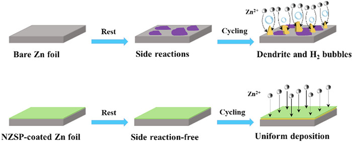
Among MIBs, aqueous zinc-ion batteries (ZIBs) have attracted huge attention since the direct use of Zn metal anode with a low redox potential and high theoretical capacity [7-11]. However, the Zn anode still possesses some shortcomings. The Zn anode suffers from corrosion and passivation layer formation due to the side reactions when it contacts with electrolyte. During the plating/stripping process, the uneven electric field at the surface of Zn foil leads to ununiform Zn2+ nucleation and deposition and followed by dendrite formation due to the "tip effect". The Zn dendrites can easily pierce the separator, causing a short circuit issue. Moreover, the dendrites would break to generate "dead Zn", resulting in a low Coulombic efficiency and an increased impedance. Beside the Zn dendrite, hydrogen evolution and passivation are other issues for Zn anode. Once the hydrogen was formed, the OH−concentration would increase leading the formation of by-products (zinc hydroxides and zincates). The by-products passivate the fresh Zn, which inhibits the further reaction of Zn and increases the impedance (Fig. 1, upper case) [12]. These abovementioned issues lead to the unsatisfied cycling life and inferior capacity of ZIBs.

|
Download:
|
| Fig. 1. Schematic illustration of zinc deposition behavior for zinc foil (upper case) and NZSP-coated Zn foil (lower case). | |
In order to address abovementioned issues, various strategies have been developed to stabilize the Zn metal anode, such as electrolyte optimization [13-22], separator modification [23-26], structure design [27], and interface engineering [28-32]. Among these approaches, Zn interface engineering has demonstrated as a facile and effective approach especially directly fabricating a protection layer on Zn surface [33-38]. Most used protection layers not only serve as a physical layer to avoid side reactions between Zn metal and electrolyte, but also enable a uniform Zn plating/stripping underneath the protection layer suppressing dendrite formation [39-42]. However, these protective layers may induce a large overpotential due to the inferior Zn2+ conductivity especially at high current density due to the presence of additional layer [43-45]. For example, Cao et al. [43] adopted cyanoacrylate adhesive (502 glue) as artificial solid/electrolyte interphase on the Zn metal surface. The protective layer effectively prevented dendrite formation and side reactions, leading to prolonged cycle life in symmetric cells and improved electrochemical performance in full cells. However, a larger overpotential in symmetric cells based on modified Zn metal was observed as compared with that of symmetric cells based on bare Zn metal, which may be induced by unsatisfied Zn2+ conductivity. In addition, Deng et al. [44] reported that the excess of kaolin coating would increase the charge-transfer resistance because of the low ionic conductivity of kaolin coating. Therefore, it is crucial to fabricate a protective layer with a high ionic conductivity to enable fast Zn2+ transportation through the protective layer.
Fast ion conductor as solid-state electrolyte protection layer is a promising choice due to its high ionic conductivity. Liu et al. [46] reported NaTi2(PO4)3 protection layer on Zn metal anode. NaTi2(PO4)3 protection layer not only prevents the dendrite formation and sides reaction between Zn metal and electrolytes, but also enables reversible and uniform Zn deposition due to its high ionic conductivity. As a result, improved electrochemical performance in symmetric cells and full cells combined with MnO2 was achieved. However, NaTi2(PO4)3 is not electrochemical stable due to the presence of Ti4+, and the dissolution of Ti in the electrolyte was verified by inductively coupled plasma test. Herein, we prepared Na3Zr2Si2PO12 (NZSP) coating on Zn metal as protection layer via a facile drop casting approach. The NZSP protection layer with a high ionic conductivity of 2.94 mS/cm is conducive for the uniform Zn deposition and reducing the overpotential during the plating/stripping procedure, leading to a dendrite-free morphology. Moreover, the protective layers served as a physical layer to avoid side reactions, dendrite formation, and hydrogen evolution (Fig. 1, lower case). Consequently, the symmetric cells based on NZSP-coated Zn (NZSP-Zn) reach a long-term cycle life of 1360 h at 0.5 mA/cm2 and 1000 h at 5 mA/cm2, while the full cells coupled with V2O5-based cathode also show an improved capacity and rate capability.
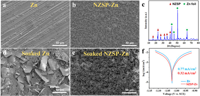
The characterization of ZNSP powder is presented in Figs. S1 and S2 (Supporting information). The X-ray diffraction (XRD) pattern of ZNSP matches well with that of monoclinic Na3Zr2Si2PO12 with a space group of C2/c (PDF No. 04–008–8579), indicating the high purity of the ZNSP. Scanning electron microscopy (SEM) image of ZNSP demonstrated that ZNSP shows a morphology of irregular shaped micrometer-sized particles. The morphologies of the bare Zn and NZSP-Zn are shown in Figs. 2a and b. Zn metal foil shows several wear scars on the surface, because it was polished with sandpaper to wipe off the oxides (Fig. 2a). After coating NZSP via a drop casting approach, it is clear to observe that the Zn surface was coated with a uniform NZSP protection layer with a thickness of ~10 µm (Fig. 2b and Fig. S3 in Supporting information). The energy dispersive X-ray spectroscopy (EDS) mappings of NZSP-Zn further confirm the uniform coating of NZSP (Fig. S4 in Supporting information). Furthermore, both NZSP and Zn diffraction peaks are observed in XRD pattern of NZSP-Zn, indicating that the structure of NZSP maintained after coating process (Fig. 2c). The self-corrosion resistance of Zn and NZSP-Zn was studied via immersing in the electrolyte (2 mol/L ZnSO4 aqueous solution) for 48 h, and the morphologies of Zn and NZSP-Zn are characterized via SEM. Hexagonal flakes Zn4SO4(OH)6·xH2O were formed on the surface of bare Zn after soaking in the ZnSO4 electrolyte, which is ascribed to the side reaction between Zn and ZnSO4 solution (Fig. 2d). The formed loose Zn4SO4(OH)6·xH2O cannot act as protection layer and prevent the further reactions between Zn and electrolyte, leading to battery swelling due to the hydrogen evolution [47]. As a sharp contrast, the NZSP-Zn surface shows similar morphology to primal without observing obvious by-products (Fig. 2e), since the NZSP protective layer prevents the direct contact between Zn and ZnSO4 solution, reducing the side reactions. The corrosion rate of Zn and NZSP-Zn anodes were evaluated with Tafel curves in the ZnSO4 solution using a three-electrode system (Fig. 2f). NZSP-Zn displays a smaller corrosion current of 0.32 mA/cm2 than that of Zn (0.77 mA/cm2), suggesting the reduced corrosion rate because the introduction of NZSP protection layer avoids the direct contact between ZnSO4 solution and Zn. The NZSP coating shows a high electronic resistance of ~ 3.9 × 10⁵ Ω cm, which avoids the Zn deposit on the NZSP coating surface (Fig. S5 in Supporting information). More importantly, the NZSP coating delivers a high ionic conductivity of 2.94 mS/cm and NZSP-Zn symmetric cells demonstrates an improved Zn2+ transference number (0.76), suggesting the cation-controlled ion conduction (Figs. S6 and S7 in Supporting information). The ZNSP is consisted of octahedra ZrO6 and tetrahedra Si/PO4 (Fig. S8 in Supporting information) [48]. Such structure creates a ''hexagonal bottleneck'' with the shortest diameter of 4.6 Å, which enables the Zn2+ with an ionic radius of 0.74 Å migration [49]. Table S1 (Supporting information) shows the ionic conductivity comparison of this work with other reported works.

|
Download:
|
| Fig. 2. SEM images of (a) Zn and (b) NZSP-coated Zn metal foils. (c) XRD pattern of NZSP-coated Zn metal. SEM images of (d) Zn metal foil and (d) NZSP-coated Zn metal after soaking in 2 mol/L ZnSO4 aqueous electrolyte for 48 h. (f) Tafel curves of Zn and NZSP-Zn metal foils. | |
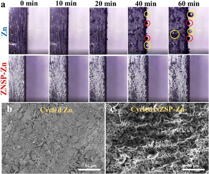
The Zn deposition behavior on Zn and NZSP-Zn and gas evolution are investigated by in situ optical microscopy at 10 mA/cm2. The surface morphology of Zn and NZSP-Zn is relatively smooth before the Zn2+ deposition. After depositing 20 min, protrusions appear due to non-uniform Zn2+ deposition. When the depositing time reaches 40 min, the protrusions evolve to dendrites as red circuit marked and some small gas bubbles appear as marked with yellow circuit owing to hydrogen evolution, and these phenomena is more severe for 60 min deposition. In a sharp contrast, the surface of NZSP-Zn remains relatively smooth without obvious dendrites and bubbles as the state of original due to dendrite suppression and reduced side reactions (Fig. 3a). In addition, the Zn deposition and cycled morphology was also investigated by SEM. After plating 2 mAh/cm2 at 0.5 mA/cm2, Zn shows a porous and bumpy surface morphology consisted of Zn dendrites owing to the non-uniform Zn nucleation and deposition (Fig. S9a in Supporting information). The NZSP-Zn keeps a same surface morphology with original, demonstrating the uniform deposition of Zn2+ under the NZSP protective layer (Fig. S9b in Supporting information). Moreover, the EDS result of surface of deposited NZSP-Zn only showed negligible Zn content (2.29 at%) and no obvious Zn is observed in the elemental mappings of cross-section of NZSP coating of deposited NZSP-Zn, further suggesting deposition of Zn2+ under the NZSP protective layer (Figs. S10 and S11 in Supporting information). After 10 cycles at 0.5 mA/cm2 with 0.5 mAh/cm2, the Zn shows a lot of flake dendrites (Fig. 3b), while the NZSP-Zn anodes still keep original surface morphology (Fig. 3c). In addition, the XRD pattern of Zn after cycling demonstrated the formation of new phase due to the side reactions, while NZSP-Zn maintains the pristine phase (Fig. S12 in Supporting information). These results revealed that the NZSP protective layer guides the uniform Zn deposition, prevents Zn dendrites growth and hydrogen evolution.

|
Download:
|
| Fig. 3. (a) In situ optical micrograph images of the cross-section of Zn (upper case) and NZSP-Zn (lower case) at 10 mA/cm2 for different deposition time. Red circle marks the Zn protuberances, yellow marks the hydrogen gas bubbles. SEM images of (b) Zn and (c) NZSP-Zn after 10 cycles at 0.5 mA/cm2 with 0.5 mAh/cm2. | |
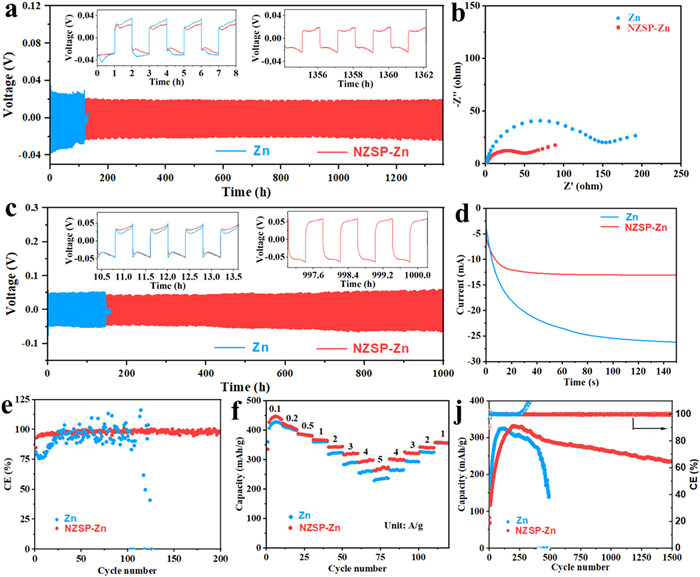
The symmetric cells were assembled and the electrochemical performance was evaluated and compared to further study the effect of NZSP coating (Figs. 4a and c). Symmetric cells based on NZSP-Zn delivers a long-term stable cycling over 1360 h with a small overpotential of -19 mV at 0.5 mA/cm2, while Zn only displays a short cycle life of 120 h with a high overpotential of ~26 mV. Even at 5 mA/cm2, the symmetric cells based on NZSP-Zn still exhibit excellent stable cycling over 1000 h (Fig. 4c), and these results overperforms the previous reports (Table S2 in Supporting information). The electrochemical impedance spectroscopy (EIS) of symmetric batteries was tested to evaluate the transfer kinetics (Fig. 4b and Fig. S13 in Supporting information). The symmetric cells based on NZSP-Zn exhibit a smaller charge transfer resistance than that of the cells based on Zn before cycling and after cycling, demonstrating a fast transfer kinetics. To further illustrate the deposition mechanism, chronoamperometry (CA) was performed (Fig. 4d). The nucleation procedure was reflected with the current change versus time at a constant applied potential (−150 mV). For the Zn, the current still increase beyond 150 s, suggesting a long 2D transfer procedure and rough deposition of Zn2+. The Zn2+ would tend to deposit on the prominent sites, thus Zn2+ aggregates to form Zn dendrites. For the NZSP-Zn, the 2D transfer procedure occurred within 20 s. Afterwards, a constant 3D diffusion proceeds with the stable current density, which indicates that the Zn2+were locally reduced at the interface. This result could be ascribed to that the NZSP protection layer offered an additional barrier for Zn2+ to move laterally. Therefore, Zn2+is locally deposited at the primal region, generating the uniform nucleation seeds and homogeneous Zn layer. The coulombic efficiency (CE) was explored with battery configuration of Zn//Ti and Zn//NZSP-Ti at 0.5 mA/cm2 (Fig. 4e). The Zn//Ti battery shows a fluctuation CE, while Zn//NZSP-Ti battery maintains high and stable CE over 200 cycles, indicating that NZSP protection layer contributes to reversible Zn2+ plating/stripping.

|
Download:
|
| Fig. 4. (a) Cycling performance of symmetric cells based on Zn and NZSP-Zn electrodes at 0.5 mA/cm2 with 0.5 mAh/cm2 (inset: enlarged voltage profiles at specific time). (b) Nyquist plots of symmetric cells based on Zn and NZSP-Zn electrodes before cycling. (c) Cycling performance of symmetric cells based on Zn and NZSP-Zn electrodes at 5 mA/cm2 with 2 mAh/cm2 (inset: enlarged voltage profiles at specific time). (d) Zn deposition behavior in symmetric cells based on Zn and NZSP-Zn electrodes. (e) Coulombic efficiency of Zn//Ti and Zn//NZSP-Ti at 0.5 mA/cm2. (f) Rate performance of Zn//V2O5@PEDOT and NZSP-Zn//V2O5@PEDOT. (j) Long-term cycling performance of Zn//V2O5@PEDOT and NZSP-Zn//V2O5@PEDOT at 2 A/g. | |
The electrochemical performance of full batteries coupled with V2O5-based cathode was evaluated to further verify the impact of NZSP protective layer. The SEM image of V2O5@PEDOT shows an irregular shaped micrometer scaled particle morphology and V2O5@PEDOT maintains the structure of V2O5 after PEDOT coating, because the XRD pattern of V2O5@PEDOT matches well the reference (PDF No. 41–1426) (Figs. S14 and 15 in Supporting information). For verifying the electrochemical performance of NZSP-Zn//V2O5@PEDOT, the rate performance measurement is performed. The NZSP-Zn//V2O5@PEDOT battery delivers capacities of 446, 422, 387, 367, 342, 316, 289, 262 mAh/g at 0.1, 0.2, 0.5, 1, 2, 3, 4, 5 A/g, which are higher that of Zn//V2O5@PEDOT battery, especially at high current densities (Fig. 4f). More importantly, the NZSP-Zn//V2O5@PEDOT batteries maintain a capacity of 250 mAh/g after 1500 cycles at 2 A/g, while Zn//V2O5@PEDOT batteries show a capacity decay with an increase CE (Fig. 4j). The initial capacity of NZSP-Zn//V2O5@PEDOT is lower than that of Zn//V2O5@PEDOT in Figs. 4f and j as well as NZSP-Zn//V2O5@PEDOT shows a low capacity at the first 160 cycles at high current density of 2 A/g in Fig. 4j due to the activation process for electrolyte infusion into electrode. The inferior electrochemical performance of Zn//V2O5@PEDOT may be ascribed to the "dead Zn" and passivation layer formation [50]. The NZSP protective layer with a high ionic conductivity reduced the side reactions and hydrogen evolution, prevented Zn dendrites and "dead Zn" formation, and improved Zn2+ transport kinetics, thus NZSP-Zn//V2O5@PEDOT batteries show high rate capability and cycling stability. Table S3 (Supporting information) shows the electrochemical performance comparison of this work with other reported works.
In conclusion, a fast ion conductor NZSP as protection layer on Zn metal anode was fabricated for enhanced aqueous ZIBs via a drop casting approach. NZSP protection layer prevented the side reactions between Zn and electrolyte, guided uniform zinc deposition, and reduced Hydrogen evolution, which were verified by in situ optical microscopy and SEM images. In addition, the high ionic conductivity of NZSP contribute to a fast transport of Zn2+ for zinc deposition/dissolution. As a result, a stable and prolonged cycle life were achieved in symmetric cells, and enhanced rate capability as well as long-term cycling stability in full cells were realized for NZSP-Zn. This work indicated that NZSP protection layer with a high ionic conductivity is effective in preventing the Zn dendrite, hydrogen evolution, and side reactions.
Declaration of competing interestThe authors report no declarations of interest.
AcknowledgmentsThis work is supported by Feitian Scholar Program of Gansu Province and Youth Doctoral Fund of Education Department of Gansu Province (No. 2021QB-115) and Innovation Fund of Education Department of Gansu Province (No. 2022A-138).
Supplementary materialsSupplementary material associated with this article can be found, in the online version, at doi:10.1016/j.cclet.2022.07.046.
| [1] |
F. Cheng, J. Liang, Z. Tao, et al., Adv. Mater. 23 (2011) 1695-1715. DOI:10.1002/adma.201003587 |
| [2] |
B. Sun, Q. Lu, K. Chen, et al., Adv. Mater. 34 (2022) 2108682. DOI:10.1002/adma.202108682 |
| [3] |
Q. Lu, A. Omar, L. Ding, et al., J. Mater. Chem. A 9 (2021) 9038-9047. DOI:10.1039/d1ta00066g |
| [4] |
F. Xu, C. Qu, Q. Lu, et al., Sci. Adv. 8 (2022) eabm7489. DOI:10.1126/sciadv.abm7489 |
| [5] |
D. Chao, W. Zhou, F. Xie, et al., Sci. Adv. 6 (2020) eaba4098. DOI:10.1126/sciadv.aba4098 |
| [6] |
Y. Zhang, L. Zhao, Y. Liang, et al., eScience 2 (2022) 110-115. DOI:10.1016/j.esci.2022.01.002 |
| [7] |
N. Zhang, X. Chen, M. Yu, et al., Chem. Soc. Rev. 49 (2020) 4203-4219. DOI:10.1039/c9cs00349e |
| [8] |
Y.H. Du, X.Y. Liu, X.-.Y. Wang, et al., Rare Metals 41 (2022) 415-424. DOI:10.1007/s12598-021-01777-2 |
| [9] |
P. Ruan, S. Liang, B. Lu, et al., Angew. Chem. Int. Ed. 61 (2022) e202200598. |
| [10] |
H. Liu, J.G. Wang, Z. You, et al., Mater. Today 42 (2021) 73-98. DOI:10.1016/j.mattod.2020.08.021 |
| [11] |
Z. Wang, M. Zhou, L. Qin, et al., eScience 2 (2022) 209-218. DOI:10.1016/j.esci.2022.03.002 |
| [12] |
Q. Li, L. Han, Q. Luo, et al., Batteries Supercaps 5 (2022) e202100417. |
| [13] |
M. Han, J. Huang, X. Xie, et al., Adv. Funct. Mater. (2022) 2110957. DOI:10.1002/adfm.202110957 |
| [14] |
Y. Li, P. Wu, W. Zhong, et al., Energy Environ. Sci. 14 (2021) 5563-5571. DOI:10.1039/d1ee01861b |
| [15] |
B. Zhang, L. Qin, Y. Fang, et al., Sci. Bull. 67 (2022) 955-962. DOI:10.1016/j.scib.2022.01.027 |
| [16] |
K. Wu, F. Ning, J. Yi, et al., J. Energy Chem. 69 (2022) 237-243. DOI:10.1016/j.jechem.2022.01.037 |
| [17] |
Z. Zhao, J. Wang, Z. Lv, et al., Chem. Eng. J. 417 (2021) 128096. DOI:10.1016/j.cej.2020.128096 |
| [18] |
H. Qiu, R. Hu, X. Du, et al., Angew. Chem. Int. Ed. 61 (2022) e202113086. |
| [19] |
Y. Dong, L. Miao, G. Ma, et al., Chem. Sci. 12 (2021) 5843-5852. DOI:10.1039/d0sc06734b |
| [20] |
M. Yang, J. Zhu, S. Bi, et al., Adv. Mater. 34 (2022) 2201744. DOI:10.1002/adma.202201744 |
| [21] |
S. Liu, R. Zhang, J. Mao, et al., Sci. Adv. 8 (2022) eabn5097. DOI:10.1126/sciadv.abn5097 |
| [22] |
X. Ji, eScience 1 (2021) 99-107. DOI:10.1016/j.esci.2021.10.004 |
| [23] |
Z. Hou, Y. Gao, H. Tan, et al., Nat. Commun. 12 (2021) 3083. DOI:10.1038/s41467-021-23352-0 |
| [24] |
Q. Li, B. Yan, D. Wang, et al., Small 18 (2022) 2201045. DOI:10.1002/smll.202201045 |
| [25] |
Y. Fang, X. Xie, B. Zhang, et al., Adv. Funct. Mater. 32 (2022) 2109671. DOI:10.1002/adfm.202109671 |
| [26] |
B. Wu, Y. Wu, Z. Lu, et al., J. Mater. Chem. A 9 (2021) 4734-4743. DOI:10.1039/d0ta11841a |
| [27] |
Q. Cao, H. Gao, Y. Gao, et al., Adv. Funct. Mater. 31 (2021) 2103922. DOI:10.1002/adfm.202103922 |
| [28] |
J. Yan, M. Ye, Y. Zhang, et al., Chem. Eng. J. 432 (2022) 134227. DOI:10.1016/j.cej.2021.134227 |
| [29] |
G. Liang, J. Zhu, B. Yan, et al., Energy Environ. Sci. 15 (2022) 1086-1096. DOI:10.1039/d1ee03749h |
| [30] |
Q. Yang, L. Li, T. Hussain, et al., Angew. Chem. Int. Ed. 61 (2022) e202112304. DOI:10.1002/anie.202112304 |
| [31] |
C. Xie, Q. Zhang, Z. Yang, et al., Chin. Chem. Lett. 33 (2022) 2653-2657. DOI:10.1016/j.cclet.2021.09.083 |
| [32] |
H. Liu, J.-.G. Wang, W. Hua, et al., Adv. Sci. 8 (2021) 2102612. DOI:10.1002/advs.202102612 |
| [33] |
S. Li, J. Fu, G. Miao, et al., Adv. Mater. 33 (2021) 2008424. DOI:10.1002/adma.202008424 |
| [34] |
Q. Lu, C. Liu, Y. Du, et al., ACS Appl. Mater. Interfaces 13 (2021) 16869-16875. DOI:10.1021/acsami.0c22911 |
| [35] |
Y. Liu, J. Hu, Q. Lu, et al., Energy Storage Mater 47 (2022) 98-104. DOI:10.3390/jfb13030098 |
| [36] |
N. Zhang, S. Huang, Z. Yuan, et al., Angew. Chem. Int. Ed. 60 (2021) 2861-2865. DOI:10.1002/anie.202012322 |
| [37] |
F. Tao, Y. Liu, X. Ren, et al., J. Energy Chem. 66 (2022) 397-412. DOI:10.1016/j.jechem.2021.08.022 |
| [38] |
L. Yuan, J. Hao, C.-.C. Kao, et al., Energy Environ. Sci. 14 (2021) 5669-5689. DOI:10.1039/d1ee02021h |
| [39] |
R. Chen, Q. Liu, L. Xu, et al., ACS Energy Lett. 7 (2022) 1719-1727. DOI:10.1021/acsenergylett.2c00124 |
| [40] |
R. Guo, X. Liu, F. Xia, et al., Adv. Mater. (2022) 2202188. DOI:10.1002/adma.202202188 |
| [41] |
M. Zhu, J. Hu, Q. Lu, et al., Adv. Mater. 33 (2021) 2007497. DOI:10.1002/adma.202007497 |
| [42] |
W. Yuan, G. Ma, X. Nie, et al., Chem. Eng. J. 431 (2022) 134076. DOI:10.1016/j.cej.2021.134076 |
| [43] |
Z. Cao, X. Zhu, D. Xu, et al., Energy Storage Mater. 36 (2021) 132-138. DOI:10.1016/j.ensm.2020.12.022 |
| [44] |
C. Deng, X. Xie, J. Han, et al., Adv. Funct. Mater. 30 (2020) 2000599. DOI:10.1002/adfm.202000599 |
| [45] |
Z. Yan, W. Xin, Z. Zhu, Nanoscale 13 (2021) 19828-19839. DOI:10.1039/d1nr06058a |
| [46] |
M. Liu, J. Cai, H. Ao, et al., Adv. Funct. Mater. 30 (2020) 2004885. DOI:10.1002/adfm.202004885 |
| [47] |
J. Hao, B. Li, X. Li, et al., Adv. Mater. 32 (2020) 2003021. DOI:10.1002/adma.202003021 |
| [48] |
C. Zhao, L. Liu, X. Qi, et al., Adv. Energy Mater. 8 (2018) 1703012. DOI:10.1002/aenm.201703012 |
| [49] |
K.M. Bui, V.A. Dinh, S. Okada, et al., Phys. Chem. Chem. Phys. 18 (2016) 27226-27231. DOI:10.1039/C6CP05164B |
| [50] |
Z. Li, Z. Gong, X. Wu, et al., Chin. Chem. Lett. 33 (2022) 3936-3940. DOI:10.1016/j.cclet.2021.11.015 |