 2023, Vol. 34


b University of Chinese Academy of Sciences, Beijing 100049, China;
c Fujian Provincial Key Laboratory of Featured Biochemical and Chemical Materials, Ningde Normal University, Ningde 352100, China
The pursuit of low-cost, renewable, and environmental-friendly energy sources especially hydrogen fuel has received tremendous attention in recent decades to meet the growing global energy demand and achieve carbon-neutral energy supplies [1, 2]. Photoelectrochemical (PEC) water splitting is a prospective pathway to converting solar energy into green hydrogen fuel [3-7]. Solution-processed organic semiconductors, including single polymers and donor-acceptor mixed bulk heterojunction materials, represent a class of promising photoactive materials for cost-effective, large-scale, and high-efficiency solar-driven water splitting [8].
Since the blend of poly(3-hexylthiophene) (P3HT) and [6, 6]-phenyl-C61-butyric acid methyl ester (PCBM) was used as the photoactive layer of photocathodes in PEC cell for the first time, a series of research work based on P3HT: PCBM has been carried out to optimize the onset potential, photocurrent and durability by introducing interfacial layers with well-matched energy levels, including hole transporting layer (HTL, such as CuI, MoO3, PEDOT: PSS, and graphene oxide), electron transfer layer (ETL, such as TiO2) and catalytical layer (such as Pt, MoSx, and RuO2) [9-11]. However, the optimized photocurrent of photocathode based on P3HT: PCBM was only obtained to −8 mA/cm2 at 0 V vs. reference hydrogen electrode (RHE) with an onset potential of 0.7 V vs. RHE [12]. In recent years, the performance of bulk heterojunction (BHJ) based photocathode for hydrogen evolution reaction (HER) has made great progress, benefiting from the rapid development of novel non-fullerene acceptors, which possess significant advantages including broad absorption band, high crystallinity, and tunable energy levels [13]. For example, by using the non-fullerene acceptor, Li and coworkers have improved the photocurrent density of BHJ-based photocathodes to −11.7 and 11.98 mA/cm2 at 0 V vs. RHE with onset potentials of 0.8 and 0.87 V vs. RHE, respectively [13, 14].
Since the organic semiconductor, Y6 ((2, 2′-((2Z, 2′Z)-((12, 13-bis(2-ethylhexyl)-3, 9-diundecyl-12, 13-dihydro-[1, 2, 5]thiadiazolo[3, 4-e]thieno[2′′, 3′′: 4′, 5′]thieno[2′, 3′: 4, 5]pyrrolo[3, 2-g]thieno[2′, 3′: 4, 5]thieno[3, 2-b]indole-2, 10-diyl)bis(methanylylidene))bis(5, 6-difl-uoro-3-oxo-2, 3-dihydro-1H-indene-2, 1-diylidene))dimalononitrile)), was first reported by Zou' group in 2019, PM6 (poly[(2, 6-(4, 8-bis(5-(2-ethylhexyl-3-fluoro)thiophen-2-yl)-benzo[1, 2-b: 4, 5-b′]dithiophene))-alt-(5, 5-(1′, 3′-di-2-thienyl-5′, 7′-bis(2-ethylhexyl)benzo[1′, 2′-c: 4′, 5′-c′]dithiophene-4, 8-dione))]): Y6 based BHJ device has achieved a high PCE of 15.7% in organic solar cells (OSCs) [15]. After that, PM6 (electron donor): Y6 (electron acceptor) based BHJ has attracted tremendous interest in OSCs applications in virtue of their recombination losses, small dissociation barrier, long diffusion length, beneficial morphology, and excellent light absorption properties [16, 17]. They have not yet been investigated as photocathodes for PEC water reduction. The rapid development of PM6:Y6 BHJ for organic photovoltaics provides an opportunity to take it as a photoactive layer for solar water reduction.
Although the interfacial layers are commonly required to boost charge separation and reduce recombination [18], the multilayer structure will increase the contact resistances hence lowering the PEC performance and making the charge transfer mechanism more complicated [10]. In addition, the electrochemical degradation of the HTLs (PEDOT: PSS, MoO3) has a negative impact on both the PEC performance and the long-term stability of the photocathodes [19]. It has been suggested the large potential difference between the Fermi levels of the HTL and the electrolyte is responsible for the high onset potential and photocurrent of the photocathode [20]. We assumed that utilizing a donor material with low-lying highest occupied molecular orbital (HOMO) level and high hole mobility might make an HTL unnecessary [21]. Moreover, it has been proven that charge transfer at the BHJ/electrolyte interface is a rate-limiting process. Due to its supercapacitive nature, excellent catalytical properties, and good conductivity, RuO2 can be decorated on the BHJ surface as an interfacial layer, resulting in effective charge extraction, charge transfer, and catalyzing H+ to H2 [22, 23].
Based on these different observations, together with the low HOMO level (−5.54 eV) of PM6, we used PM6:Y6 as the photoactive layer with RuO2 as an interfacial modification layer to fabricate a simplified BHJ based photocathode, resulting in the highest photocurrent density of −15 mA/cm2 at a bias of 0 V vs. RHE, compared with a lower photocurrent density of −12 mA/cm2 with TiO2 and Pt as interfacial modification layers. The single RuO2 layer significantly lowers the device resistance, and the morphology and thickness of RuO2 play key roles in promoting the PEC performance. Moreover, the fabrication of the photocathodes could be carried out from the solution and at temperatures never going over 150 ℃.
The chemical structures of PM6 and Y6 were depicted in Fig. 1a. Both the donor and the accepter have large π-conjugated skeletons, resulting in broad absorption in the UV-vis spectra. As shown in Fig. 1b, the absorption spectra of PM6 film are well complementary with Y6 film, resulting in a very high spectral response in the range of 300–900 nm. The suitable light absorption and energy levels of PM6:Y6 make it an excellent candidate photoactive layer that can be designed as a photocathode. Since lack of reactive sites on pristine BHJ for driving water splitting, a catalytic layer is indispensable to transfer photo-generated electrons. Pt and RuO2 are the most efficiently and commonly used cocatalysts for reducing H+ to H2 [24]. TiO2 was selected as an ETL to enhance charge extraction and reduce recombination from BHJ [25]. Fig. 1c depicts three configurations of photocathodes studied in this work based on PM6:Y6 blends and different interfacial layers: (1) fluorine-doped tin oxide (FTO)/BHJ/Pt, (2) FTO/BHJ/TiO2/Pt, and (3) FTO/BHJ/RuO2.

|
Download:
|
| Fig. 1. (a) Chemical structures of PM6 and Y6. (b) Absorption spectra of the PM6, Y6, and the BHJ (PM6:Y6) film. (c) The energy-level diagram of semiconductors and photocathodes with different architectures that used in this work. | |
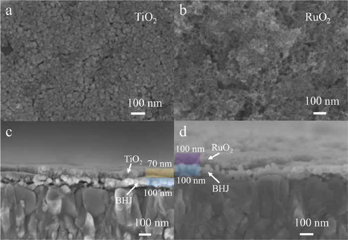
To meet the requirements of low-cost fabrication and high-throughput industrial implementation, all the three architectures are fabricated by solution-processed methods under ambient atmosphere. The experimental procedures are described in Supporting information. The Pt nanoparticles were loaded by photo-assisted electrodeposition. The active layer (BHJ) and interfacial layers (TiO2 or RuO2) were spin-coated orderly on the FTO to fabricated facile photocathodes. The surface morphology and thickness of photocathode layers were characterized by high-resolution scanning electron microscopy (SEM). The Pt nanoparticles decorated on the BHJ surface by photo-assisted electrodeposition with a particle size of 5–20 nm can be clearly observed (Fig. S1 in Supporting information). As shown in Figs. 2a and b, the TiO2, and RuO2 nanoparticles are covered uniformly on the BHJ with an average thickness of about 70 and 100 nm (Figs. 2c and d), respectively. In fact, the RuO2 layer consists of a porous layer of nanoparticle aggregates, thus its roughness is much higher than that of TiO2, thus not only offering a higher amount of reaction sites originating from the enhanced surface area but also shortening the diffusion length of charge carriers. Well-defined interfaces are observed from the cross-sectional SEM images, except for the Pt nanoparticles, whose small size and sparse distribution make them difficult to be distinguished. Therein, the optimized thickness of BHJ is about 80–150 nm.

|
Download:
|
| Fig. 2. SEM images of photocathodes with different architectures. Top-view SEM images of (a) FTO/BHJ/TiO2/Pt and (b) FTO/BHJ/RuO2 photocathodes. Cross-sectional images of the photocathodes with different interfacial layers. From bottom to top: (c) FTO, BHJ, TiO2 and Pt layers; (d) FTO, BHJ and RuO2 layers. Scale bar: 100 nm. | |
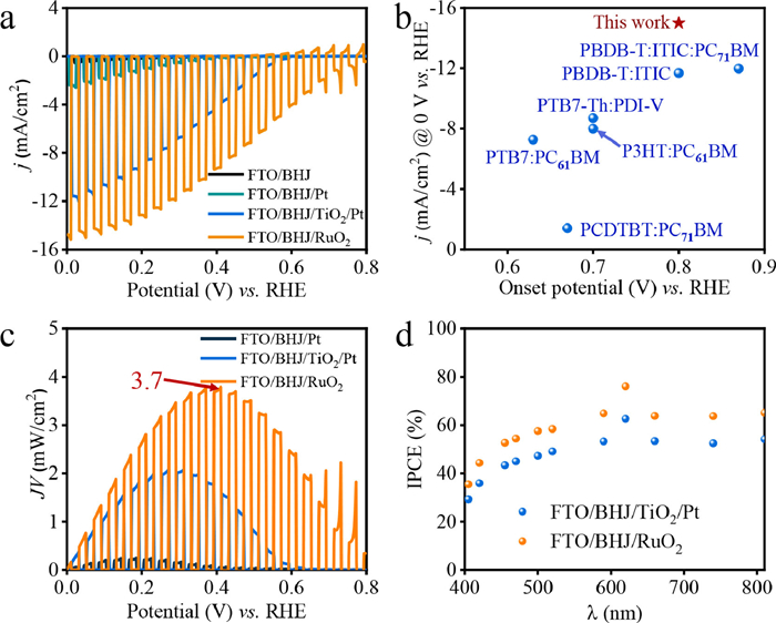
It has been proved that the FTO/BHJ/RuO2 photocathode demonstrates the highest performance for PEC HER in acidic solution than in neutral and alkali solution (Fig. S2 in Supporting information). The PEC performance of photocathodes with different architectures was then examined and compared under 1 sun (AM 1.5 G) in a 0.5 mol/L Na2SO4 electrolyte (pH 1). The bare FTO/BHJ exhibits neglect photocurrent when the photocathode was conducted by cycle voltammetry at a scan rate of 20 mV/s in the potential range of 0.8 to 0 V vs. RHE under chopped light illumination. The current-potential (J-V) curves of four different photocathodes are plotted in Fig. 3a. After Pt deposition, the photocurrent density (j) of FTO/BHJ/Pt is effectively improved due to the existence of reactive sites for HER. However, the discrete distribution of Pt nanoparticles leads to limited charge extraction. The addition of TiO2 overlayer significantly promotes charge separation and electron transfer, therefore, the FTO/BHJ/TiO2/Pt photocathode is capable of delivering a high photocurrent of −12 mA/cm2 at 0 V vs. RHE. Nevertheless, the additional interface will increase the resistance toward the charge flow and thus is harmful to the PEC performances [26]. An interfacial layer that undertakes the tasks of charge extraction, electron transfer, and catalysis is urgently desired. RuO2 is a good alternative. In comparison with that of FTO/BHJ/TiO2/Pt photocathode, the saturation photocurrent density of FTO/BHJ/RuO2 is greatly enhanced and reaches a record photocurrent value of −15 mA/cm2 at 0 V vs. RHE with an onset potential of 0.8 V vs. RHE (at 0.1 mA/cm2). To the best of our knowledge, the j at 0 V vs. RHE is the highest value among the previously reported BHJ-based photocathodes (Fig. 3b). In addition, the performance of the FTO/BHJ/TiO2/RuO2 photocathode is not superior to FTO/BHJ/RuO2 photocathode (Fig. S3 in Supporting information), indicating that the RuO2 could efficiently promote charge transfer. The ideal ratiometric power-saved efficiency (Φsaved, ideal, see Supporting information for details) of the photocathodes could be obtained according to their maximum power point (mpp) calculated from the J-V curves(Fig. 3c). The Φsaved, ideal of FTO/BHJ/RuO2 photocathode is determined to be 3.7% at 0.4 V vs. RHE, which is nearly twice higher than that of FTO/BHJ/TiO2/Pt photocathode (1.9% at 0.3 V vs. RHE), while the value of FTO/BHJ/Pt photocathode is below 0.2%. Thanks to the broad light absorption range, the incident-photon-to-current efficiency (IPCE) spectra of the photocathodes at 0 V vs. RHE show a wide and high-efficiency response in the whole range of 300–900 nm. The highest IPCEs of 76% and 69% are achieved at about 620 nm for FTO/BHJ/RuO2 and FTO/BHJ/TiO2/Pt photocathodes, respectively (Fig. 3d).

|
Download:
|
| Fig. 3. (a) J-V curves of FTO/BHJ, FTO/BHJ/Pt, FTO/BHJ/TiO2/Pt and FTO/BHJ/RuO2 photocathodes under solar spectrum AM1.5 G at 100 mW/cm2 with chopped light illumination in 0.5 mol/L Na2SO4 aqueous solution (pH 1). (b) Summary of the onset potential and current density (at 0 V vs. RHE) of state-of-the-art BHJ-based photocathodes. (c) Identification of the maximum power point (mpp) of the different photocathodes according to their J-V curves: FTO/BHJ/Pt, FTO/BHJ/TiO2/Pt, and FTO/BHJ/RuO2. (d) IPCE spectra of FTO/BHJ/RuO2 and FTO/BHJ/TiO2/Pt photocathodes in 0.5 mol/L Na2SO4 (pH 1) electrolyte with an applied potential of 0 V vs. RHE. | |
To identify the feasibility of the FTO/PM6:Y6/RuO2 photocathode with an HTL-free structure, HTL was introduced to investigate its effect on the PEC performance of the photocathode. We chose two commonly used HTL materials (NiO and CuOx) to fabricate FTO/NiO/BHJ/RuO2 and FTO/CuOx/BHJ/RuO2 photocathodes. As shown in Fig. S4 (Supporting information), due to the low hole mobility and conductivity of NiO, the onset potential of FTO/NiO/BHJ/RuO2 is only 0.5 V vs. RHE with a photocurrent density of −10.5 mA/cm2 at 0 V vs. RHE, indicating that an unsuitable HTL might block the hole transport. Previous studies suggest that CuOx is a favorable material for extracting photo-generated holes [13, 14, 27]. However, the onset potential and photocurrent are not improved compared with the HTL-free photocathode. We inferred that the invalidation of HTL might be ascribed to the high energy difference between the HOMO level of PM6 and the electrolyte (1.1 V vs. Vacuum).
The thickness and morphology of RuO2 that impact the carrier transport behavior are critical to achieving high PEC performance [28]. As plotted in Fig. S5 (Supporting information), when the RuO2 layer is not thick enough (below 100 nm), the BHJ surface could not be fully covered by RuO2. Hence the active sites and electron extraction are insufficient. On the contrary, too thick a RuO2 layer causes a dramatic increase in charge transfer resistance and decreases in both photocurrent and onset potential. Therefore, a moderate thickness of the RuO2 layer is a key point to obtain a saturated J-V curve. Meanwhile, the photocathode with the thickness of both BHJ and RuO2 below 100 nm exhibits similar charge separation efficiency under the front and the back side illumination (Fig. S6 in Supporting information). The mass ratio of PM6:Y6 was also explored in Fig. S7 (Supporting information), and the optimized mass ratio is 1:1.2. It is worth mentioning that the PEC performance of the photocathode is insensitive to the variation of temperature, which means the device has a good working characteristic (Fig. S8 in Supporting information).
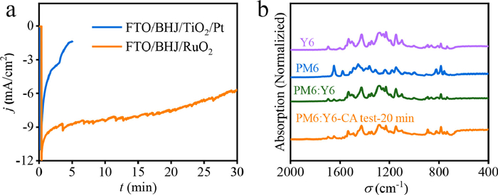
To test the durability of the photocathodes, chronoamperometry (CA) measurements were carried out at a bias of 0.1 V vs. RHE in a 0.5 mol/L Na2SO4 electrolyte (pH 1). As shown in Fig. 4a, the photocathode based on TiO2 and Pt interlayers degrades rapidly, the photocurrent decreases by 90% in less than 5 min. This is caused by the poor contact between the BHJ and TiO2 nanoparticles and the loose structure of the TiO2 layer. As a result, the TiO2 layer was detached from the BHJ surface, accompanied by the Pt layer. In comparison, with RuO2 as the interlayer, -50% of the photocurrent loss occurred after 30 min. The reason for the moderate degradation speed of the FTO/BHJ/RuO2 photocathode might be that although exfoliation occurred on the RuO2 layer as well, the newly exposed RuO2 interface continued to undertake the task of electron transfer and catalysis. The chemical structures of pristine PM6, Y6, BHJ, and BHJ after the CA test were characterized by microscopic infrared spectroscopy (Micro-FTIR) using the attenuated total reflectance (ATR) method at room temperature. The spectra of BHJ after the PEC test is consistent with that as-prepared (Fig. 4b), which exhibits the main characteristic peak signals of both pristine PM6 and Y6. The results indicate that the chemical structure of BHJ has not been damaged during the PEC process. As a result, the low stability of the BHJ-based photocathodes may be caused by delamination of overlayers from the BHJ surface or exfoliation of BHJ from FTO substrates, erosion of electrolyte, and electrochemical polarization. The continuous evolution of H2 bubbles was observed over the surface of the FTO/BHJ/RuO2 photocathode for about 1 h with a faradaic efficiency of nearly 100% (Fig. S9 in Supporting information).

|
Download:
|
| Fig. 4. (a) Stability test of FTO/BHJ/TiO2/Pt and FTO/BHJ/RuO2 photocathodes under solar spectrum AM1.5 G at 100 mW/cm2 at a bias of 0.1 V vs. RHE in 0.5 mol/L Na2SO4 aqueous solution (pH 1) with trace of H2PtCl4. (b) FTIR-ATR characterization of PM6, Y6, FTO/BHJ (PM6:Y6)/RuO2, and FTO/BHJ/RuO2 after CA test for 20 min. | |
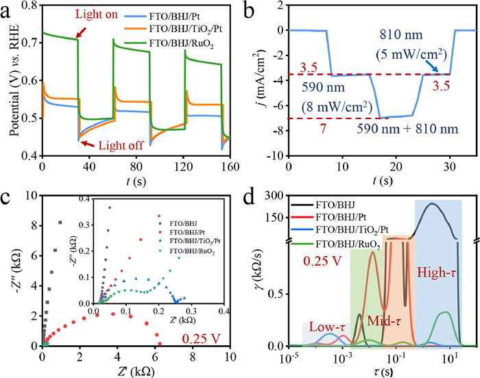
Open-circuit potential (OCP) measurements were performed to estimate the relative photovoltages of the different photoelectrodes, their OCP curves are shown in Fig. 5a. Under illumination, the OCP for FTO/BHJ/Pt, FTO/BHJ/TiO2/Pt, and FTO/BHJ/RuO2 photocathodes move toward the positive direction, indicating p-type semiconductor properties, and the photovoltages are 50 mV, 100 mV, and 200 mV, respectively. The result corresponds to the tendency of the onset potential values of the photocathodes. Compared with FTO/BHJ/Pt and FTO/BHJ/TiO2/Pt, the more positive shift in the OCP under illumination for FTO/BHJ/RuO2 suggests that the RuO2 overlayer enables higher conversion efficiency of the incident light to sufficiently available photogenerated electrons, leading to improved PEC activity of PM6:Y6 based photocathode [13].

|
Download:
|
| Fig. 5. (a) Open circuit potentials were tested in a 0.5 mol/L H3BO3-KOH buffer solution with 0.5 mol/L Na2SO3 at pH 9 under chopped light illumination. (b) CA curve of FTO/BHJ/RuO2 photocathode under different light irradiation conditions at 0 V vs. RHE. (c) Nyquist plots of as-prepared FTO/BHJ, FTO/BHJ/Pt, FTO/BHJ/TiO2/Pt, and FTO/BHJ/RuO2 photocathodes at a bias of 0.25 V vs. RHE in 0.5 mol/L Na2SO4 aqueous solution (pH 1) under light illumination. Inset: original magnification 25×. (d) Distribution of relaxation times (DRT) curves converted from impedance spectra of (c). | |
It is worth mentioning that the value of photocurrent simultaneously irradiated under 590 nm and 810 nm monochromatic LED light is equal to the sum of photocurrent values that separately irradiated, indicating that there is no synergetic interaction between PM6 and Y6 (Fig. 5b).
To further study the electron transport kinetics in the four kinds of photocathodes and at their interfaces of photocathode/electrolyte, electrochemical impedance spectroscopy (EIS) measurements were conducted under light illumination at the bias from 0.05 V to 0.65 V vs. RHE (Figs. S10a–h in Supporting information). As shown in Fig. 5c, the EIS plots of the four kinds of photocathodes differ from one another. The arc radii of the FTO/BHJ photocathode is much larger than the other photocathodes, indicating its photo-generated charge separation and transfer is very difficult without an interfacial layer. From the high-magnification of the EIS plots in Fig. 5c (upper right inset), it is clearly observed that the photocathodes modified by interfacial layers show two or more arcs. The radius values of these photoelectrodes follow the order of FTO/BHJ/RuO2 < FTO/BHJ/TiO2/Pt < FTO/BHJ/Pt < FTO/BHJ, which are perfectly consistent with their corresponding photocurrent density. The resistances of FTO/BHJ/RuO2 and FTO/BHJ/TiO2/Pt photocathodes are decreased at both high and low-frequency regions due to their efficient electron extraction and transfer, increased conductivity, and enhanced interface kinetics. However, it is hard to distinguish all these contributions. Distribution of relaxation times (DRT) converted from impedance spectra was introduced to effectively separate polarization processes more clearly than in common Nyquist or Bode plots [29]. From the DRT plots (Fig. 5d), peaks can be characterized to different polarization processes based on their relaxation time (τ) in the order of series resistances (low-τ) < charge transfer (mid-τ) < interfacial reactions (high-τ) [30]. The peak intensity of FTO/BHJ/Pt and FTO/BHJ photocathodes at mid-τ and high-τ regions dramatically increases, indicating that their HER performances are hampered due to their inefficient charge transfer and limited reaction sites (Figs. S10e and f). The FTO/BHJ/TiO2/Pt photocathode obtained the weakest peak intensity in the high-τ region might be due to the excellent conductivity and catalytical properties of Pt. The weakest peak intensity of the FTO/BHJ/RuO2 photocathode in the low-τ region indicates it possesses the smallest series resistances ascribes to the simplified architecture. In addition, the loading of RuO2 effectively promotes the charge transfer in BHJ bulk and decreases the series resistance that mass transfer was the dominant process for FTO/BHJ/RuO2 photocathode (Fig. S10h) [31].
In conclusion, through the selection of PM6:Y6 BHJ as the photoactive layer and RuO2 as the interfacial layer, a facile photocathode was fabricated by the all-solution processed method. The as-obtained photocathode achieves the highest photocurrent density of −15 mA/cm2 at 0 V vs. RHE for HER compared with previous reported BHJ-based photocathodes. The value of Φsaved, ideal is up to 3.7% at 0.4 V vs. RHE. The IPCE value reaches 76% at about 620 nm. By utilizing RuO2 as an interfacial layer, an electron transfer layer is unnecessary, thus the interfacial recombination and excessive series resistances of the simplified photocathode are effectively reduced. Moreover, the positive shift of OCP of FTO/BHJ/ RuO2 photocathode is responsible for the enhancement of its onset potential. Our work provides an easy and efficient fabrication technique that can meet the requirement of high-throughput industrial implementation.
Declaration of competing interestThe authors declare no competing financial interest.
AcknowledgmentsWe acknowledge the financial support by the National Natural Science Foundation of China (NSFC, 21905288, and 51904288), the Zhejiang Provincial Natural Science Foundation (No. LZ21B030017), K.C. Wong Education Foundation (No. GJTD-2019-13), Ningbo Major Special Projects of the Plan "Science and Technology Innovation 2025" (Nos. 2018B10056, and 2019B10046), and Ningbo 3315 Program, and Natural Science Foundation of Fujian Province (No. 2021J011150).
Supplementary materialsSupplementary material associated with this article can be found, in the online version, at doi:10.1016/j.cclet.2022.04.078.
| [1] |
A.T. Hoang, H.C. Ong, I.M.R. Fattah, et al., Fuel Process. Technol. 223 (2021) 106997. DOI:10.1016/j.fuproc.2021.106997 |
| [2] |
Y. Hou, F. Zuo, A. Dagg, et al., Adv. Mater. 26 (2014) 5043-5049. DOI:10.1002/adma.201401032 |
| [3] |
S. Tang, W. Qiu, S. Xiao, et al., Energy Environ. Sci. 13 (2020) 660-684. DOI:10.1039/C9EE02986A |
| [4] |
L. Wang, X. Shi, Y. Jia, et al., Chin. Chem. Lett. 32 (2021) 1869-1878. DOI:10.1016/j.cclet.2020.11.065 |
| [5] |
Y. Hou, Z. Wen, S. Cui, et al., Adv. Mater. 25 (2013) 6291-6297. DOI:10.1002/adma.201303116 |
| [6] |
J.H. Kim, D. Hansora, P. Sharma, et al., Chem. Soc. Rev. 48 (2019) 1908-1971. DOI:10.1039/C8CS00699G |
| [7] |
Y. Hou, F. Zuo, A. Dagg, et al., Angew. Chem. Int. Ed. 52 (2013) 1248-1252. DOI:10.1002/anie.201207578 |
| [8] |
L. Steier, S. Holliday, J. Mater. Chem. A 6 (2018) 21809-21826. DOI:10.1039/C8TA07036A |
| [9] |
H.C. Rojas, S. Bellani, E.A. Sarduy, et al., ACS Omega 2 (2017) 3424-3431. DOI:10.1021/acsomega.7b00558 |
| [10] |
A. Mezzetti, F. Fumagalli, A. Alfano, et al., Faraday Discuss. 198 (2017) 433-448. DOI:10.1039/C6FD00216A |
| [11] |
L. Yao, A. Rahmanudin, N. Guijarro, K. Sivula, Adv. Energy Mater. 8 (2018) 1802585. DOI:10.1002/aenm.201802585 |
| [12] |
H.C. Rojas, S. Bellani, F. Fumagalli, et al., Energy Environ. Sci. 9 (2016) 3710-3723. DOI:10.1039/C6EE01655C |
| [13] |
W. Shi, D. Li, W. Fan, et al., Adv. Funct. Mater. 30 (2020) 2003399. DOI:10.1002/adfm.202003399 |
| [14] |
S. Ye, W. Shi, Y. Liu, et al., J. Am. Chem. Soc. 143 (2021) 12499-12508. DOI:10.1021/jacs.1c00802 |
| [15] |
J. Yuan, Y. Zhang, L. Zhou, et al., Joule 3 (2019) 1140-1151. DOI:10.1016/j.joule.2019.01.004 |
| [16] |
S. Dong, K. Zhang, T. Jia, et al., EcoMat 1 (2019) e12006. |
| [17] |
C. Zhang, Z. Wang, H. Li, et al., Org. Chem. Front. 7 (2020) 3001-3026. DOI:10.1039/D0QO00637H |
| [18] |
Y. Hou, Z. Wen, S. Cui, et al., Nano Lett. 16 (2016) 2268-2277. DOI:10.1021/acs.nanolett.5b04496 |
| [19] |
S. Bellani, L. Najafi, B. Martín-García, et al., J. Phys. Chem. C 121 (2017) 21887-21903. DOI:10.1021/acs.jpcc.7b05904 |
| [20] |
T. Bourgeteau, D. Tondelier, B. Geffroy, et al., J. Mater. Chem. A 4 (2016) 4831-4839. DOI:10.1039/C6TA01320A |
| [21] |
T.H. Lee, R.R. Rao, R.A. Pacalaj, et al., Adv. Energy Mater. (2022) 2103698. |
| [22] |
L. Yao, N. Guijarro, F. Boudoire, et al., J. Am. Chem. Soc. 142 (2020) 7795-7802. DOI:10.1021/jacs.0c00126 |
| [23] |
H. Over, Chem. Rev. 112 (2012) 3356-3426. DOI:10.1021/cr200247n |
| [24] |
C.G. Morales-Guio, S.D. Tilley, H. Vrubel, et al., Nat. Commun. 5 (2014) 3059. DOI:10.1038/ncomms4059 |
| [25] |
L. Steier, S. Bellani, H.C. Rojas, et al., Sustain. Energy Fuels 1 (2017) 1915-1920. DOI:10.1039/C7SE00421D |
| [26] |
M. Haro, C. Solis, V.M. Blas-Ferrando, et al., ChemSusChem 9 (2016) 3062-3066. DOI:10.1002/cssc.201600961 |
| [27] |
W. Shi, W. Yu, D. Li, et al., Chem. Mater. 31 (2019) 1928-1935. DOI:10.1021/acs.chemmater.8b04629 |
| [28] |
P. Nowakowski, A. Kopia, S. Villain, et al., J. Microsc. 237 (2010) 246-252. DOI:10.1111/j.1365-2818.2009.03236.x |
| [29] |
T.H. Wan, M. Saccoccio, C. Chen, et al., Electrochim. Acta 184 (2015) 483-499. DOI:10.1016/j.electacta.2015.09.097 |
| [30] |
R. Attias, K. Vijaya Sankar, K. Dhaka, et al., ChemSusChem 14 (2021) 1737-1746. DOI:10.1002/cssc.202002946 |
| [31] |
Y. Hou, F. Zuo, P. Feng, et al., Nano Lett. 12 (2012) 6464-6473. DOI:10.1021/nl303961c |