 2022, Vol. 33


b Ningbo Institute of Northwestern Polytechnical University, Ningbo 315103, China;
c School of Science, Hainan University, Haikou 570228, China
Lithium–sulfur (Li–S) batteries adopt an electrode couple of high-capacity sulfur cathode (1675 mAh/g) and lithium metal anode (3861 mAh/g) to deliver an outstanding energy density of 2654 Wh/kg, which surpasses commercialized lithium-ion (Li-ion) batteries (350 Wh/kg at a cell level in practice) and promises materials sustainability and cost efficiency [1-6]. In the last decades, we have witnessed tremendous achievements in sulfur cathodes, embracing scaffold design (porosity and tortuosity) [7-9], interface modification (chemisorptivity and catalysis) [10-16], cell structure development (interlayer) [17-21], binder selection [22-27], flexible prototype concept [28-30], and in-depth understanding of sulfur species evolution [31-38]. These efforts have resulted in impressive electrochemical performances in some aspects, such as high areal loading (> 8 mg/cm2), long cyclability (> 1000 cycles), high-rate capability (> 5 C), although concurrently realized these targets remain great challenges [39]. One of bottlenecks that hinders their overall enhancements of battery performances is the troublesome lithium metal anode [40-44].
The successfully bringing liquid Li–S batteries to a reality has to overcome issues surrounding the Li metal anode. The dynamic evolution of lithium metal anode involves lithium plating/striping coupled with lithium polysulfide (LiPS) electrochemical reactions in the working Li–S batteries, which are root causes of many problematic issues. The commonly used electrolyte recipes in liquid Li–S batteries are 1.0 mol/L lithium bis(trifluoromethanesulfony)imide (LiTFSI) in ethylene glycol dimethyl ether (DME) and 1,3-dioxolane (DOL) (v:v = 1:1) with 1.0 ~ 5.0 wt% anhydrous lithium nitrate (LiNO3) [45]. Such ether-based electrolytes can readily decompose and re-polymerize on the surface of the metallic lithium, forming a solid electrolyte interphase (SEI) containing organic and inorganic components to forbidden excessive exhaustion of bulk electrolytes and naked lithium [46,47]. The ideal SEI is expected to be spatially homogenizing, electronically insulating, ionically conducting and mechanically stabilizing. However, the naturally formed SEI is brittle and fragile, and exhibits mosaic fashion with abundant defects and grain boundaries [48,49]. This causes two critical problems. First, the continuous lithium plating beneath SEI incurs progressive tensile stress, rendering crack of SEI and exposure of naked lithium, which promote the formation of fresh SEI to heal the crack. Such self-healing mechanism thickens SEI, until depletion of electrolyte and lithium. Second, the rapid lithium flux in the crack favors the growth of lithium dendrites. The protrusion of lithium with high curvature attracts more lithium to preferentially plate on it, leading to self-acceleration of dendrite propagation. The self-healing and self-acceleration occurred on the lithium metal anode worsen electrolyte and consume cycleable lithium, which are exacerbated by the electrochemical/chemical reactions of LiPSs on the lithium metal anode.
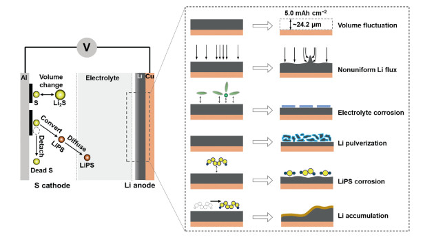
In this perspective, we categorize challenges of lithium metal anode into volume fluctuation, nonuniform lithium flux, electrolyte corrosion, lithium pulverization polysulfide corrosion and massive lithium accumulation, and discuss their origins in Li–S batteries. The possible solutions to tackle these problems are outlined, focusing on the reducing local current density, strengthening SEI, promoting Li-ion conductivity and shielding corrosive solvents/LiPSs. Based on distinguished mass and charge migration in Li–S batteries, we highlight the importance of the pouch cell in the practical evaluation of battery performances. This Perspective calls attention to the lithium metal anode in high-energy and high-power Li–S batteries.
2. Challenges of lithium metal anodeThe challenges of lithium metal anode are schematically summarized in Fig. 1. The following subjections individually discuss them, with focus on their origins and consequences.

|
Download:
|
| Fig. 1. The failure mechanisms of the lithium metal anode in working Li–S batteries. | |
In order to be competitive with commercial Li-ion batteries, the areal capacity of sulfur cathode needs to surpass 5 mAh/g [50]. Considering the mass density (0.534 g/cm3) and capacity (3861 mAh/g) of metallic lithium, 1 mAh/cm2 corresponds to a thickness of 4.85 μm, implying that fully and densely stripping and plating of lithium leads to huge thickness fluctuations (24.2 µm). It is of note that such thickness variation does not take into account of the lithium dendrite and fragment whose formation tends to form thick and porous interphase, and the final thickness fluctuation is much higher than 24.2 µm. The considerable volume change destabilizes the fragile SEI and fractures the dendrite, which are essential causes of poor Coulombic efficiency and limited cycle life in the high-sulfur-loading Li–S batteries. In addition, the practical cells include multiple layers of sulfur cathode and lithium anode, which alternately stack together to attain desired voltage and capacity. Take the regular cell used in vehicles with a capacity of 30 Ah and a dimension of 161 × 227 mm, the prismatic cell should contain at least 21 unit cells, corresponding to a thickness variation of ~0.5 mm theoratically upon cycling, which require additional approaches to keep cell and module stable and integration. The actual volume variation of Li–S pouch cell is dynamically probed by Waluś et al. [51]. The pouch cell with a capacity of 11 ± 0.5 Ah experienced a thickness change as high as 0.2 mm in the initial cycle, and reached to a maximum of ~0.5 mm in the third cycle. Given that the number of unit cell scales with the cell capacity, the cell with 30 Ah would suffer a thickness change of 1.5 mm.
2.2. Nonuniform lithium fluxNonuniform lithium flux is influenced by two major factors. The first one is the nonuniform surface of lithium metal anode. Rips, cracks, bulges, dent, and impurities, which possess greater interfacial energy, act as nucleation sites to seed lithium clusters and aid the subsequent propagations. The lithium nucleation and growth cause a redistribution of electrical fields, especially in the tip of lithium protrusion and dendrite. Another factor is the separator pores and channels, which allow charge species to pass. The separator pores and channels have inherently greater lithium flux than the separator scaffold. In the fast charge condition, the limited diffusion of lithium ions would lead to the accumulation of lithium on the anode surface that directly contacts with separator pores and channels, rendering nonuniform Li flux and augment of lithium dendrite.
2.3. Electrolyte corrosionThe potential that is beyond the highest occupied molecular orbital (HOMO) and lowest unoccupied molecular orbital (LUMO) of electrolytes leads to electrolyte decompositions [52]. The ultralow potential of lithium metal anode spontaneously breaks down the molecules of free solvents, anions and solvated lithium salts, forming a protective SEI layer to retard further electrolyte decompositions. However, as discussed above, the fragile SEI tends to fracture and expose fresh lithium to react with electrolytes, which can be aggravated by high areal capacity and large current density. Constructing an effective SEI that ideally isolates electrolyte from lithium anode while remains rapid lithium conduction is a kernel in the optimization of electrolyte recipes and searching of new lithium salts, solvents and additives. Mitigating or even avoiding electrolyte corrosion is the prioritized consideration in the design of high-energy Li–S batteries that advocates limited lithium and lean electrolyte.
2.4. Lithium pulverizationLithium pulverization upon cycling is closely related to lithium volume change and lithium dendrite formation. The lithium dendrite with a high length-to-diameter ratio readily initiates a thin SEI around its surface at beginning, and progressively evolves in a thick one through continuous reaction of lithium and electrolyte. If the root of the lithium dendrite completely develops into SEI that traps all moveable lithium by forming organic or inorganic lithium species, the electron transport is then blocked and the remaining metallic lithium cannot be re-unitized. Even being electrically connected with parent lithium, the soft dendrite may detach when it experiences external (shaking and pressing) or internal (volume-change induced strain) forces. The continuous lithium dendrite and SEI formation, as well as huge volume fluctuation, cause a large number of fine lithium particles that permanently isolate from the lithium anode, leading to consumption and depletion of cycleable lithium or electrolytes. Fang et al. quantified unreacted lithium and SEI lithium in various electrolyte compositions, and found that the unreacted lithium could be > 70% in the first cycle [53]. Lacking of efficient approaches to resume the lithium would finally cause lithium pulverization.
2.5. LiPS corrosionLiPSs can be regarded as redox active species in the electrolyte, and their corrosion to the lithium metal anode concurrently takes place with other electrolyte components. Once soluble LiPSs occurs in the sulfur cathode, they migrate toward the lithium metal anode and are reduced to the short-chain LiPSs through oxidizing the metallic lithium. The short-chain LiPSs ruin the interface of lithium anode through two routes. The first one is the further reduction of LiPSs to Li2S2 and Li2S, which deposit on the lithium surface. The formation of Li2S2 and Li2S consumes additional lithium and impedes lithium transfer across the interface, which takes responsibility to the increase of cell resistance. The recent study demonstrates that LiPSs could aggravate the nonuniform stripping of lithium electrodes [54]. The second one is the “shuffle” of naked lithium by internal LiPS shuttle, leading to porous or loose lithium surface. The long-chain LiPSs originated from the cathode side chemically oxidize the low-chain LiPSs to produce middle-chain LiPSs and release lithium (for example, Li2S6 + 2Li2S2 = 2Li2S5 + 2Li), which may deposit/absorb on the surface of the lithium anode. The middle-chain LiPSs are, again, reduced to low-chain LiPSs by reacting with lithium (for example, 2Li2S5 + 6Li = 5Li2S2). Such internal cycle of diverse LiPSs, manifesting as low Coulombic efficiency in the battery performance, is also a critical origin to evolve in porous lithium surface or “dead” lithium.
2.6. Lithium motion and accumulationLithium accumulation not only takes place in the dendrite formation, but also occurs in the cell-level dimension. The origin of lithium motion and accumulation in the entire cell dimension is the mobility of LiPSs. The external press, uneven sulfur distribution in cathode layer (before cycling) and gas evolution collectively lead to nonuniform pressure in the cell, which contribute to migration and diffusion of moveable LiPSs toward low pressure area. Upon cycling, the LiPSs functioned as lithium carrier take away lithium, and accumulate on the low-pressure areas, which hints lean lithium in other areas [55]. The massive lithium migration and accumulation impact battery performances from two aspects. The lithium-lean area cannot provide sufficient lithium in the lithiation of sulfur during discharging process, leading to incomplete conversion of sulfur. The lithium-rich area in anode commonly corresponds sulfur-rich area of the cathode. The heavy sulfur accumulation significantly slows down reaction kinetics from soluble LiPSs to insoluble Li2S2/Li2S. Both lithium-lean and lithium-rich areas of the lithium anode reduce sulfur utilization and increase the cell resistance.
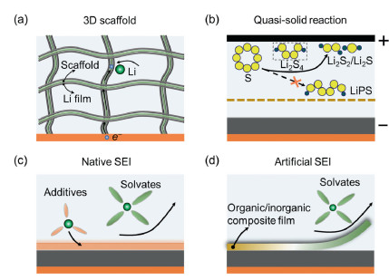
3. Efficient working lithium metal anodeEfficient lithium metal anode in Li–S batteries call for comprehensive designs in bulk and interface, which are associated with scaffold, electrolyte and artificial layer.
3.1. Developing 3D scaffold3D scaffold has been extensively explored in the lithium metal anode due to two considerations (Fig. 2a). The first one is the expansion of surface area that can access electrolyte to promote lithium plating and stripping. Taking an areal capacity of 5 mAh/cm2 for example, the total surface area of a graphite anode with porous structure can reach to 714 cm2 in a unit area (cm2), assuming the graphite anode having a specific surface area of 5 m2/g and delivering a capacity of 350 mAh/g. However, the dense planar metallic lithium with a unit area, theoretically, exhibits only 1 cm2 to contact with electrolytes, indicating almost three magnitudes of higher current density than the graphite anode, which is one of critical causes to easily develop lithium dendrites in the lithium anode in comparison with the graphite anode. 3D scaffold could significantly increase surface area to access electrolyte and reduce local current density, which contribute to the low value of sand's time to regard lithium dendrite formation [56].

|
Download:
|
| Fig. 2. Approaches to achieve efficient lithium metal anodes in Li–S batteries. (a) Developing 3D scaffold; (b) exerting quasi-solid reaction; (c) tailoring native SEI; and (d) designing artificial SEI. | |
Another consideration lies in the buffering volume change of lithium and mitigating thus-induced surface stress. As discussed in Section 2, the lithium metal anode experiences extensive volume change upon electrochemical plating and stripping, leading to lithium surface strain due to elevating and dropping lithium surface. Continuously elevating and dropping lithium surface also move separator and sulfur cathode layer back and forth, deteriorating the integration of sulfur cathode structure. 3D scaffold with sufficient pore structures underpins the anode layer, and accommodates guest lithium, eliminating volume fluctuation incurred instability of both sulfur cathode and lithium anode.
3.2. Exerting quasi-solid reactionLiquid Li–S battery chemistry adopts a dissolution–precipitation mechanism, leading to massive charge and mass transport across the entire cell space. Once the soluble LiPSs are formed, the electrical field and concentration gradient push LiPSs toward lithium metal anode, on which the redox reactions take places to corrode lithium surface. The clear-cut approach is to explore new reaction routes that can directly convert sulfur into Li2S2/Li2S without formation of moveable LiPSs, by which the LiPS-incurred corrosion of the lithium metal anode is expected to be mitigated (Fig. 2b). Smaller sulfur molecules (S2–4) confined in microporous carbon matrix is proposed to exclude the presence of high-order LiPSs [57]. This strategy allows the employment of carbonate-based electrolytes, which is unapplicable in the Li–S cell that produce high-order LiPSs. However, the S2–4 cathode composite hardly exceeds sulfur content of 50 wt%, against the requirement of high sulfur content in energy-dense Li–S batteries.
An alternative approach that bypasses highly soluble LiPSs is to use sparingly solvating electrolyte, which functions as a medium to transport charge rather than takes strong responsibility to dissolve LiPSs [58,59]. The concept of sparingly solvating electrolyte is proposed to decouple the reaction pathway from electrolyte volume [60]. The sparingly solvating electrolyte does not necessarily convert sulfur to Li2S2/Li2S directly, but, in most cases, forms mild soluble species, such as Li2S4, to locally mediate reaction pathways. Lee et al. observed a voltage dip at around 400 mAh/g in the discharge profile, corresponding to ~1/4 electron per S atom and suggesting a formation of a nominal Li2S4 according to Faraday's law [61]. The mild soluble Li2S4 alleviates the energy barrier in the sulfur conversion, while prevent significant shuttle of redox active sulfur species. In addition, the commonly used hydrofluoroethers (HFE) in sparingly solvating electrolyte tend to preferentially decompose on lithium metal anode and form favorable F-rich SEI to protect lithium anode [62].
3.3. Tailoring native SEIModification of native SEI involves optimization of solvents and salts that decompose on the lithium metal anode, forming an ionically conductive and electrically insulating layer (Fig. 2c). The principle of tailoring SEI is in the regulation of electrolyte solvation chemistry to adjust solvent/salt deposition consequences, alter organic/inorganic composition, and modify SEI thickness, which conjunctively render mechanically and electrochemically desirable film for efficient cycling of Li–S batteries. Once lithium salts dissolve in solvents, the lithium salts are anticipated to disassociate into lithium and anion through the interactions of lithium and electron-donating atoms on solvents (e.g., O and N), creating solvates that form stoichiometric lithium and solvent (like Li(DME)4) [63].
In practice, adjusting electrolyte concentration and selecting electrolyte additives are popularized in tailoring SEI [64,65]. Increase of electrolyte concentration exhausts free solvents and favors formation of solvates, by which the electrolyte structure shifts the location of LUMO from solvents to lithium salts, rendering preferential decomposition of lithium salts instead of solvents [66]. The vast decomposition of lithium salts in concentrated electrolyte, thereby, significantly tunes SEI composition and structure, showing a promising strategy to refine SEI. However, high concentration electrolyte is costly and usually results in sluggish redox kinetics of sulfur conversion. Electrolyte design is a paramount strategy linking to the protection of Li metal anode through modification of Li surface properties and regulation of charge carrier transport. Firstly, the selected electrolyte formulation, including lithium salt and solvent, should be at least kinetically stabilized against reductive lithium metal anode to avoid extensive breakdown electrolyte. Secondly, delocalization of electrons in the entire solvent and lithium salt anion is prerequisite to enable LiPS compatibility. The electrolyte recipes with remarkable positively charged atoms are readily attacked by nucleophilic LiPS, which is the root cause for widely used ether solvents instead of carbonate solvents in the Li–S batteries. Additional benefits, such as low viscosity, high lithium transport, reasonable lithium transference number and sufficient electrochemical voltage window, are also critical to mediate LiPS conversion and transportation.
Electrolyte additives in the design of SEI are most likely the sacrificing lithium salts or solvents. LiNO3 is a representative additive in the electrolyte, allowing the operation of Li–S batteries with a high Coulombic efficiency of > 99%. The small amount of “magic” LiNO3 does not impact redox kinetics, while keep the efficient cycling of lithium anode until its depletion. To date, a range of salt additives have been explored to protect lithium metal anode [67,68], but none of them are as efficient as LiNO3. The mechanism of lithium anode protection by LiNO3 is attributed to the formation of inorganic species such as LiNxOy and organic species such as ROLi and ROCO2Li [47,69,70]. However, the detailed mechanisms remain ambiguous. For example, what kinds of LiNO3-derived N or Li species contribute to high Li conduction? How is the coordination environment of such species? Is it possible to replace LiNO3 by N containing solvents or salts to mimic LiNO3 decomposed byproducts? Accordingly, further efforts are urgently needed, either by experimental or computational techniques, to reveal underlying mechanisms. Solvent additives have also been searched to develop high-quality SEI. The reduction of HFE on the lithium metal anode facilitates formation of F-rich SEI, which has been considered to promote the lithium conductivity. It is of note that the efficient electrolyte additives that have been proved in lithium-metal batteries with metal oxide cathodes may be inefficient in Li–S batteries due to two possible issues. First, the carbonate and ether electrolytes are used in conventional lithium-metal batteries and Li–S batteries, respectively. The efficient additives in carbonate-based electrolyte may be incompatible to ether-based electrolyte, such as fluoroethylene carbonate (FEC) [71]. Second, the LiPS corrosion has to be considered in the formation of SEI. The presence of sulfate and sulfite compounds (Li2S2O3 and Li2SO4) derived from LiPSs [72] may weak the protection efficiency.
3.4. Designing artificial SEIThe native SEI composed of inorganics and organics is fragile and cannot withstand volume change induced strain and tolerate LiPS corrosion. Artificial SEI takes advantages of rationally rearranging organic and inorganic components to generate desired mechanical flexibility (Fig. 2d), ionic conductivity and spatial hermeticity, by which ion flux can be redistributed, mass migration can be impeded and volume fluctuation can be buffered [73-76].
The mechanical flexibility of artificial SEI mainly considers two functions: sufficient Young's modulus and high flexibility. The SEI layer should has sufficient Young's modulus to bear volume change and suppress lithium dendrite formation. It is suggested that the Young's modulus greater than 6 GPa could mitigate lithium dendrite formation [77], whereas some reports doubt this conclusion, arguing that the local environment plays more important role [78]. The artificial SEI should also possess high flexibility, as the large volume change occurs in the lithium striping and plating. The flexibility is ubiquitously realized by engineering polymer scaffold, which can be further reinforced by inorganic fillers. The commonly used polymer scaffolds include poly(vinylidene-co-hexafluoropylene) (PVDF-HFP) and polyethylene oxide (PEO) [79,80]. Designing high Young's modulus and flexibility of artificial SEI in LiPS contain electrolytes still remain challenge.
Lithium conductivity plays critical role in determination of lithium striping and plating, especially in the high current density and large areal capacity. The artificial SEI is normally much thicker than native SEI. The lithium conductivity of artificial SEI should principally be significantly higher than that of native SEI in order to keep similar redox kinetics. Assuming the native and artificial SEI with thicknesses of 100 nm and 10 μm, respectively, the lithium conductivity of the latter should be two magnitudes higher than the former. Therefore, selecting and processing appropriate lithium salts, polymer scaffolds and fillers are key to realizing sufficient lithium conductivity. The abundancy and diversity of inorganic (LiF, Li3N) or organic (ROCO2Li, Li alkoxides and Li alkylcarbonates) lithium species have been proposed to greatly increase conductivity of artificial SEI [81].
Spatial hermeticity, in this discussion, means that the artificial SEI perfectively prevent solvents, solvates and LiPSs migration from bulk electrolyte to lithium metal surface while permit rapid lithium transport. Most of previous works emphasizes lithium conductivity and mechanical flexibility, while the spatial hermeticity of artificial SEI has been underappreciated. The lithium corrosion is attributed to solvents and LiPSs attack. The effective artificial SEI layers that have been proved in lithium metal batteries with oxide cathodes may be ruined by LiPS etching. Once the artificial SEI establishes a pathway (probably through cracks or grain boundaries) for LiPS migration, the solution mediated lithium and electron transports continuously render chemical reactions with surface lithium, thereby worsening the composition and structure of artificial SEI and lithium metal anode.
In the real-world Li–S batteries, the protection of lithium metal anode cannot be achieved by adoption of one or two approaches that are discussed above, but requires multiple considerations from bulk to interface. For example, the lithium metal anode with 3D scaffolds should be covered by efficient native or artificial SEI that can shield LiPSs and electrolytes. Otherwise, the enlarged surface area of lithium metal anode enabled by 3D scaffolds suffers more severe side reactions comparing with planar lithium foil.
4. Toward reliable lithium metal anode: from coin cell to pouch cellTremendous efforts have been devoted to Li–S batteries, covering cathode hosts, electrolyte recipes and anode protections, while most of them takes coin-type cell as the test protocol, which cannot fully reflect the intrinsic problems of practical Li–S batteries [82,83]. The coin-type cell is regarded as a half-cell configuration that does not take lithium metal anode into consideration. The pouch cell, a ubiquitous cell prototype in practical evaluation, is more reliable, as it underlines the balance of entire cell components to obtain high energy/power densities and long cycle life [84].
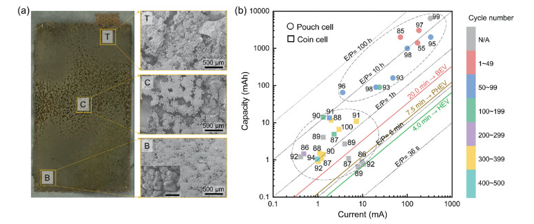
Taking a pouch cell with a size of 30 × 50 mm for example, the total current applied in the pouch cell is 15 times higher than a coin cell (~1 cm2). Once nonuniform current density occurred in the anode side, a high current probably exerts on a certain area, leading to the promotion of lithium dendrite. The nonuniform electrochemical reactions and LiPS migration contribute to an inhomogeneous lithium deposition, as indicated in Fig. 3a. Another critical difference lies in the sulfur to electrolyte ratio (E/S) and the thickness of lithium foil. The E/S ratio is rarely less than 5.0 in coin cells due to wetting separator, filling cathode pores, and flowing out of electrodes, while pouch cell constrains E/S < 4.0 to achieve desired energy density. The negative to positive capacity ratio (N/P) in coin and pouch cells are ~100 and ~4, respectively, in case of low sulfur loading (1.0 mg/cm), thick lithium foil (500 µm) in coin cell, and high sulfur loading (5.0 mg/cm), thin lithium foil (100 µm) in pouch cell. Such stringent testing conditions in the pouch cell result in rapid capacity fading, low power delivery and early cell death [55,85].

|
Download:
|
| Fig. 3. Lithium metal anode in pouch cell. (a) Massive lithium migration in lithium anode sheet. Reproduced with permission [55]. Copyright 2019, Wiley-VCH. (b) Total capacity and current loaded in Li–S batteries with coin and pouch cells. | |
The above analysis highlights the importance of the total capacity (mAh) and total current (mA) loaded on the lithium metal anode in practical considerations, instead of academically used capacity (mAh/g or mAh/cm2) and current density (mA/g or mA/cm2). Fig. 3b abstracts recent advances in the design of coin and pouch Li–S cells in metrics of total capacity and current [37,38,55,76,85-100], which are selected after 5 ~ 10 cycles due to quick capacity fading in the initial several cycles. The gray dash line represents an energy to power ratio (E/P) that is a critical indicator to screen battery systems for the application of diverse electric vehicles (EVs), ranging from battery exclusively powered electric vehicles (BEVs), plug-in electric vehicles (PHEVs) and hybrid electric vehicles (HEVs) [101]. The coin-type cell seldom exceeds a capacity of 20.0 mAh and a current of 10.0 mA, while the pouch cell has × 10 to × 100 times greater capacity and current, which contributes drastic degradation of cycle life (< 100 cycle). In the current stage, the E/P of the pouch cell is far from the requirements of EVs, and most of them are in the level of > 5 h. One of decisive factor is the easy damage of lithium metal anode under demanding lithium stripping/plating capacity and current in the pouch cell. The coin-type cell with limited capacity (< 1 mAh) has the possibility to fall into value of E/P< 20 min, but it is meaningless in practical applications.
5. Conclusion and outlookDeveloping reliable lithium metal anode is a decisive task to realize well-performing Li–S batteries in practical test protypes. Surpassing commercial Li-ion batteries needs an areal capacity of 5 mAh/cm2 in Li–S batteries, which cause high volume fluctuation of the lithium metal anode. The large amount of lithium plating and stripping destabilize the SEI and may lead to complex design in the cell and module integration. The imperfect lithium metal surface and uneven pore distribution of separator induce nonuniform lithium flux, triggering lithium dendrite formation and propagation. The developed lithium dendrites and porous lithium surface accelerate electrolyte and LiPS corrosion, which concurrently consume and deplete electrolytes, lithium metal anode and active sulfur, rendering short cycle life. The moveable redox active sulfur species result in lithium accumulation in a certain area and early exhaustion in other areas in the cell. This lithium motion and accumulation is a key origin for the nonhomogeneous redox kinetics in the planar electrode. Beside, the fragile lithium dendrite, considerable volume change and continuous electrolyte corrosion bring about lithium pulverization, reducing amount of cycleable lithium.
The current approaches to achieve efficient lithium metal anodes include bulk and interface designs. 3D scaffold could effectively buffer lithium volume change and reduce local current density, retaining the quality of native or artificial SEI and retarding the formation of lithium dendrite. LiPS migration and electrochemical reactions between LiPS and lithium anode undermine the stability of SEI and augment surface resistance. The straightforward approach is the adoption of quasi-solid reactions by employment of smaller sulfur molecular and sparingly solvating electrolyte, by which the soluble LiPS can be curtailed or be localized. Tailoring native SEI by adjusting electrolyte recipes is extensively explored in view of importance of electrolyte-dependent SEI, large spectrum of available electrolyte materials, and efficiency of lithium metal protection. While LiNO3 additive is regarded a critical leap to achieve Coulombic efficiency of > 99%, there is ample headroom to optimize electrolyte solvation structure to promote LiPS redox kinetics and protect lithium metal anode. Artificial SEI rationally rearranges organic and inorganic components to create desired layer that possesses mechanical flexibility, ionic conductivity and spatial hermeticity, which synergistically contribute stable lithium anode interface.
The critical differences between coin and pouch cells include sulfur content (wt%), sulfur loading (mg/cm2), electrolyte to sulfur ratio (mL/g) and negative to positive capacity ratio (N/P). The test conditions in the pouch cell are more stringent comparing with coin cells in terms of these metrics. The total capacity and current loaded on the pouch cell are × 10 to × 100 times higher than coin cells. Nonuniform distribution of current and mass in the planar electrode sheet severely impacts the lithium metal anode and battery performances. Constructing reliable lithium metal anode that can follow the EV requirements of E/P is imperative in pouch cells, instead of pursuit of high capacity and long cyclability under low areal sulfur loading in coin cells.
Declaration of competing interestThe authors declare that they have no known competing financial interests or personal relationships that could have appeared to influence the work reported in this paper.
AcknowledgmentsThis work was supported by the National Natural Science Foundation of China (Nos. 21805162, 22102132 and 21905056), Shenzhen Natural Science Foundation (No. JCYJ202110324104412034), Natural Science Foundation of Shaanxi Province, China (Nos. 2021JQ-087, 2020JM-141), and Ningbo Natural Science Foundation (Nos. 202003N4054, 202003N4006 and 2021J053).
| [1] |
J.B. Robinson, K. Xi, R.V. Kumar, et al., J. Phys. Energy 3 (2021) 031501. DOI:10.1088/2515-7655/abdb9a |
| [2] |
Y. Chen, T. Wang, H. Tian, et al., Adv. Mater. 33 (2021) 2003666. DOI:10.1002/adma.202003666 |
| [3] |
Z. Shi, M. Li, J. Sun, Z. Chen, Adv. Energy Mater. 11 (2021) 2100332. DOI:10.1002/aenm.202100332 |
| [4] |
L. Kong, C. Yan, J.Q. Huang, et al., Energy Environ. Mater. 1 (2018) 100-112. DOI:10.1002/eem2.12012 |
| [5] |
C. Yang, Appl.Energy 306 (2022) 118116. DOI:10.1016/j.apenergy.2021.118116 |
| [6] |
C. Yang, P. Li, J. Yu, L.D. Zhao, L. Kong, Energy 201 (2020) 117718. DOI:10.1016/j.energy.2020.117718 |
| [7] |
Y. Song, X. Li, C. He, Chin. Chem. Lett. 32 (2021) 1106-1110. DOI:10.1016/j.cclet.2020.08.024 |
| [8] |
S. Jiang, S. Huang, M. Yao, et al., Chin. Chem. Lett. 31 (2020) 2347-2352. DOI:10.1016/j.cclet.2020.04.014 |
| [9] |
M. Zhao, Y.Q. Peng, B.Q. Li, X.Q. Zhang, J.Q. Huang, J. Energy Chem. 56 (2021) 203-208. DOI:10.1016/j.jechem.2020.07.054 |
| [10] |
L. Kong, Y. Handa, I. Taniguchi, Mater. Res. Bull. 73 (2016) 164-170. DOI:10.1016/j.materresbull.2015.08.036 |
| [11] |
H. Yuan, H.J. Peng, B.Q. Li, et al., Adv. Energy Mater. 9 (2019) 1802768. DOI:10.1002/aenm.201802768 |
| [12] |
H.J. Peng, J.Q. Huang, X.Y. Liu, et al., J. Am. Chem. Soc. 139 (2017) 8458-8466. DOI:10.1021/jacs.6b12358 |
| [13] |
R. Wang, C. Luo, T. Wang, et al., Adv. Mater. 32 (2020) 2000315. DOI:10.1002/adma.202000315 |
| [14] |
Z. Fan, C. Zhang, W. Hua, et al., J. Energy Chem. 62 (2021) 590-598. DOI:10.1016/j.jechem.2021.04.038 |
| [15] |
C. Zhang, L. Cui, S. Abdolhosseinzadeh, J. Heier, InfoMat 2 (2020) 613-638. DOI:10.1002/inf2.12080 |
| [16] |
F. Li, L. Wang, G. Qu, et al., Chin. Chem. Lett. (2021). DOI:10.1016/j.cclet.2021.11.046 |
| [17] |
Y.S. Su, A. Manthiram, Chem. Commun. 48 (2012) 8817-8819. DOI:10.1039/c2cc33945e |
| [18] |
S. Yang, R. Xiao, T. Hu, et al., Nano Energy 90 (2021) 106584. DOI:10.1016/j.nanoen.2021.106584 |
| [19] |
B. Guan, X. Sun, Y. Zhang, et al., Chin. Chem. Lett. 32 (2021) 2249-2253. DOI:10.1016/j.cclet.2020.12.051 |
| [20] |
Q. Wang, H. Zhao, B. Li, et al., Chin. Chem. Lett. 32 (2021) 1157-1160. DOI:10.1016/j.cclet.2020.09.022 |
| [21] |
Z. Wei, Y. Ren, J. Sokolowski, X. Zhu, G. Wu, InfoMat 2 (2020) 483-508. DOI:10.1002/inf2.12097 |
| [22] |
H. Ye, D. Lei, L. Shen, et al., Chin. Chem. Lett. 31 (2020) 570-574. DOI:10.1016/j.cclet.2019.04.047 |
| [23] |
X. He, Z. Liu, G. Gao, et al., J. Energy Chem. 59 (2021) 1-8. DOI:10.1016/j.jechem.2020.10.002 |
| [24] |
F. Wang, L. Li, D. Lei, et al., J. Energy Chem. 43 (2020) 165-172. DOI:10.1016/j.jechem.2019.08.019 |
| [25] |
A. Rashid, X. Zhu, G. Wang, et al., J. Energy Chem. 49 (2020) 71-79. DOI:10.1016/j.jechem.2020.01.031 |
| [26] |
X. Luo, X. Lu, X. Chen, et al., J. Energy Chem. 50 (2020) 63-72. DOI:10.1016/j.jechem.2020.02.041 |
| [27] |
H. Yuan, J.Q. Huang, H.J. Peng, et al., Adv. Energy Mater. 8 (2018) 1802107. DOI:10.1002/aenm.201802107 |
| [28] |
L. Kong, C. Tang, H.J. Peng, J.Q. Huang, Q. Zhang, SmartMat 1 (2020) 1-35. |
| [29] |
B. Liu, Y. Zhang, Z. Wang, et al., Adv. Mater. 32 (2020) 2003657. DOI:10.1002/adma.202003657 |
| [30] |
Y. Liu, M. Yao, L. Zhang, Z. Niu, J. Energy Chem. 38 (2019) 199-206. DOI:10.1016/j.jechem.2019.03.034 |
| [31] |
A. Gupta, A. Bhargav, A. Manthiram, Chem. Mater. 33 (2021) 3457-3466. DOI:10.1021/acs.chemmater.1c00893 |
| [32] |
L. Kong, J.X. Chen, H.J. Peng, et al., Energy Environ. Sci. 12 (2019) 2976-2982. DOI:10.1039/C9EE01257E |
| [33] |
C. Dillard, A. Singh, V. Kalra, J. Phys. Chem. C 122 (2018) 18195-18203. DOI:10.1021/acs.jpcc.8b02506 |
| [34] |
Z. Li, H. Jiang, N.C. Lai, T. Zhao, Y.C. Lu, Chem. Mater. 31 (2019) 10186-10196. DOI:10.1021/acs.chemmater.9b03885 |
| [35] |
X.Y. Li, Q. Zhang, J. Energy Chem. 65 (2022) 302-303. DOI:10.1016/j.jechem.2021.05.039 |
| [36] |
J. Xie, Y.W. Song, B.Q. Li, et al., Angew. Chem. Int. Ed. 59 (2020) 22150-22155. DOI:10.1002/anie.202008911 |
| [37] |
C.X. Zhao, X.Y. Li, M. Zhao, et al., J. Am. Chem. Soc. 143 (2021) 19865-19872. DOI:10.1021/jacs.1c09107 |
| [38] |
M. Zhao, X. Chen, X.Y. Li, B.Q. Li, J.Q. Huang, Adv. Mater. 33 (2021) 2007298. DOI:10.1002/adma.202007298 |
| [39] |
M. Zhao, B.Q. Li, X.Q. Zhang, J.Q. Huang, Q. Zhang, ACS Cent. Sci. 6 (2020) 1095-1104. DOI:10.1021/acscentsci.0c00449 |
| [40] |
C. Yan, X.Q. Zhang, J.Q. Huang, Q. Liu, Q. Zhang, Trends Chem 1 (2019) 693-704. DOI:10.1016/j.trechm.2019.06.007 |
| [41] |
W.J. Chen, C.X. Zhao, B.Q. Li, et al., Energy Environ. Mater. 3 (2020) 160-165. DOI:10.1002/eem2.12073 |
| [42] |
R. Cao, W. Xu, D. Lv, J. Xiao, J.G. Zhang, Adv. Energy Mater. 5 (2015) 1402273. DOI:10.1002/aenm.201402273 |
| [43] |
R. Xu, X. Shen, X.X. Ma, et al., Angew. Chem. Int. Ed. 60 (2021) 4215-4220. DOI:10.1002/anie.202013271 |
| [44] |
C.B. Jin, X.Q. Zhang, O.W. Sheng, et al., Angew. Chem. Int. Ed. 60 (2021) 22990-22995. DOI:10.1002/anie.202110589 |
| [45] |
M. Barghamadi, A.S. Best, A.I. Bhatt, et al., Energy Environ. Sci. 7 (2014) 3902-3920. DOI:10.1039/C4EE02192D |
| [46] |
S.S. Zhang, J. Power Sources 231 (2013) 153-162. DOI:10.1016/j.jpowsour.2012.12.102 |
| [47] |
S. Xiong, K. Xie, Y. Diao, X. Hong, Electrochim. Acta 83 (2012) 78-86. DOI:10.1016/j.electacta.2012.07.118 |
| [48] |
S.K. Heiskanen, J. Kim, B.L. Lucht, Joule 3 (2019) 2322-2333. DOI:10.1016/j.joule.2019.08.018 |
| [49] |
J.F. Ding, R. Xu, C. Yan, et al., J. Energy Chem. 59 (2020) 306-319. |
| [50] |
S. Li, M. Jiang, Y. Xie, et al., Adv. Mater. 30 (2018) 1706375. DOI:10.1002/adma.201706375 |
| [51] |
S. Waluś, G. Offer, I. Hunt, et al., Energy Storage Mater. 10 (2018) 233-245. DOI:10.1016/j.ensm.2017.05.017 |
| [52] |
J.B. Goodenough, Y. Kim, Chem. Mater. 22 (2010) 587-603. DOI:10.1021/cm901452z |
| [53] |
C. Fang, J. Li, M. Zhang, et al., Nature 572 (2019) 511-515. DOI:10.1038/s41586-019-1481-z |
| [54] |
F. Huang, S. Wang, Y. Jie, et al., J. Energy Chem. 49 (2020) 257-261. DOI:10.1016/j.jechem.2020.02.039 |
| [55] |
L. Kong, Q. Jin, J.Q. Huang, et al., Energy Technol. 7 (2019) 1900111. DOI:10.1002/ente.201900111 |
| [56] |
R. Zhang, X.B. Cheng, C.Z. Zhao, et al., Adv. Mater. 28 (2016) 2155-2162. DOI:10.1002/adma.201504117 |
| [57] |
S. Xin, L. Gu, N.H. Zhao, et al., J. Am. Chem. Soc. 134 (2012) 18510-18513. DOI:10.1021/ja308170k |
| [58] |
L. Kong, L. Yin, F. Xu, et al., J. Energy Chem. 55 (2021) 80-91. DOI:10.1016/j.jechem.2020.06.054 |
| [59] |
M. Zhao, B.Q. Li, H.J. Peng, et al., Angew. Chem. Int. Ed. 59 (2020) 12636-12652. DOI:10.1002/anie.201909339 |
| [60] |
L. Cheng, L.A. Curtiss, K.R. Zavadil, et al., ACS Energy Lett. 1 (2016) 503-509. DOI:10.1021/acsenergylett.6b00194 |
| [61] |
C.W. Lee, Q. Pang, S. Ha, et al., ACS Cent. Sci. 3 (2017) 605-613. DOI:10.1021/acscentsci.7b00123 |
| [62] |
Y. Liu, Y. Elias, J. Meng, et al., Joule 5 (2021) 2323-2364. DOI:10.1016/j.joule.2021.06.009 |
| [63] |
H. Yang, Y. Qiao, Z. Chang, P. He, H. Zhou, Angew. Chem. Int. Ed. 60 (2021) 17726-17734. DOI:10.1002/anie.202106788 |
| [64] |
H. Li, Y. Kuai, J. Yang, et al., J. Energy Chem. 65 (2022) 616-622. DOI:10.1016/j.jechem.2021.06.036 |
| [65] |
Z. Yu, J. Zhang, C. Wang, et al., J. Energy Chem. 51 (2020) 154-160. DOI:10.1016/j.jechem.2020.03.034 |
| [66] |
Y. Yamada, J. Wang, S. Ko, E. Watanabe, A. Yamada, Nat. Energy 4 (2019) 269-280. DOI:10.1038/s41560-019-0336-z |
| [67] |
F. Wu, J.T. Lee, N. Nitta, et al., Adv. Mater. 27 (2015) 101-108. DOI:10.1002/adma.201404194 |
| [68] |
W. Zeng, M.M.C. Cheng, S.K.Y. Ng, Electrochim. Acta 319 (2019) 511-517. DOI:10.1016/j.electacta.2019.06.177 |
| [69] |
S. Duangdangchote, A. Krittayavathananon, N. Phattharasupakun, N. Joraleechanchai, M. Sawangphruk, Chem. Commun. 55 (2019) 13951-13954. DOI:10.1039/C9CC06504K |
| [70] |
X. Liang, Z. Wen, Y. Liu, et al., J. Power Sources 196 (2011) 9839-9843. DOI:10.1016/j.jpowsour.2011.08.027 |
| [71] |
X.Q. Zhang, X.B. Cheng, X. Chen, C. Yan, Q. Zhang, Adv. Funct. Mater. 27 (2017) 1605989. DOI:10.1002/adfm.201605989 |
| [72] |
A. Vizintin, L. Chabanne, E. Tchernychova, et al., J. Power Sources 344 (2017) 208-217. DOI:10.1016/j.jpowsour.2017.01.112 |
| [73] |
N. Akhtar, X. Sun, M.Y. Akram, et al., J. Energy Chem. 52 (2021) 310-317. DOI:10.1016/j.jechem.2020.04.046 |
| [74] |
Y.Q. Shen, F.L. Zeng, X.Y. Zhou, et al., J. Energy Chem. 48 (2020) 267-276. DOI:10.1016/j.jechem.2020.01.016 |
| [75] |
Y. Cai, Q. Jin, K. Zhao, X. Ma, X. Zhang, Chin. Chem. Lett. 33 (2022) 457-461. DOI:10.1016/j.cclet.2021.05.065 |
| [76] |
Y.X. Yao, X.Q. Zhang, B.Q. Li, et al., InfoMat 2 (2020) 379-388. DOI:10.1002/inf2.12046 |
| [77] |
C. Monroe, J. Newman, J. Electrochem. Soc. 150 (2003) A1377. DOI:10.1149/1.1606686 |
| [78] |
F.P. McGrogan, T. Swamy, S.R. Bishop, et al., Adv. Energy Mater. 7 (2017) 1602011. DOI:10.1002/aenm.201602011 |
| [79] |
R. Xu, X.Q. Zhang, X.B. Cheng, et al., Adv. Funct. Mater. 28 (2018) 1705838. DOI:10.1002/adfm.201705838 |
| [80] |
J. Yi, D. Zhou, Y. Liang, et al., J. Energy Chem. 58 (2021) 17-24. DOI:10.1016/j.jechem.2020.09.038 |
| [81] |
D. Kang, M. Xiao, J.P. Lemmon, Batter. Supercaps 4 (2021) 445-455. DOI:10.1002/batt.202000225 |
| [82] |
X.B. Cheng, C. Yan, J.Q. Huang, et al., Energy Storage Mater. 6 (2017) 18-25. DOI:10.1016/j.ensm.2016.09.003 |
| [83] |
A. Bhargav, J. He, A. Gupta, A. Manthiram, Joule 4 (2020) 285-291. DOI:10.1016/j.joule.2020.01.001 |
| [84] |
S. Dörfler, H. Althues, P. Härtel, et al., Joule 4 (2020) 539-554. DOI:10.1016/j.joule.2020.02.006 |
| [85] |
L. Shi, S.M. Bak, Z. Shadike, et al., Energy Environ. Sci. 13 (2020) 3620-3632. DOI:10.1039/D0EE02088E |
| [86] |
L. Kong, H.J. Peng, J.Q. Huang, et al., Energy Storage Mater. 8 (2017) 153-160. DOI:10.1016/j.ensm.2017.05.009 |
| [87] |
L. Kong, X. Chen, B.Q. Li, et al., Adv. Mater. 30 (2018) 1705219. DOI:10.1002/adma.201705219 |
| [88] |
L. Kong, B.Q. Li, H.J. Peng, et al., Adv. Energy Mater. 8 (2018) 1800849. DOI:10.1002/aenm.201800849 |
| [89] |
L. Kong, Q. Jin, X.T. Zhang, et al., J. Energy Chem. 39 (2019) 17-22. DOI:10.1016/j.jechem.2018.12.012 |
| [90] |
B.Q. Li, L. Kong, C.X. Zhao, et al., InfoMat 1 (2019) 533-541. DOI:10.1002/inf2.12056 |
| [91] |
R. Fang, S. Zhao, K. Chen, D.W. Wang, F. Li, J. Phys. Energy 2 (2020) 015003. DOI:10.1088/2515-7655/ab5997 |
| [92] |
H. Shi, Y. Dong, F. Zhou, J. Chen, Z.S. Wu, J. Phys. Energy 1 (2018) 015002. DOI:10.1088/2515-7655/aadef6 |
| [93] |
L. Luo, J. Li, H. Yaghoobnejad Asl, A. Manthiram, ACS Energy Lett. 5 (2020) 1177-1185. DOI:10.1021/acsenergylett.0c00292 |
| [94] |
X. Liu, Q. He, H. Yuan, et al., J. Energy Chem. 48 (2020) 109-115. DOI:10.1016/j.jechem.2020.01.003 |
| [95] |
P.Y. Chen, C. Yan, P. Chen, et al., Angew. Chem. Int. Ed. 60 (2021) 18031-18036. DOI:10.1002/anie.202101958 |
| [96] |
T. Liu, H. Li, J. Yue, et al., Angew. Chem. Int. Ed. 60 (2021) 17547-17555. DOI:10.1002/anie.202103303 |
| [97] |
M. Zhao, X.Y. Li, X. Chen, et al., eScience 1 (2021) 44-52. DOI:10.1016/j.esci.2021.08.001 |
| [98] |
C. Zhao, G.L. Xu, Z. Yu, et al., Nat. Nanotechnol. 16 (2021) 166-173. DOI:10.1038/s41565-020-00797-w |
| [99] |
G. Ye, M. Zhao, L.P. Hou, et al., J. Energy Chem. 66 (2022) 24-29. DOI:10.1016/j.jechem.2021.07.010 |
| [100] |
Y.W. Song, J.L. Qin, C.X. Zhao, et al., J. Energy Chem. 64 (2022) 568-573. DOI:10.1016/j.jechem.2021.05.023 |
| [101] |
D. Andre, S.J. Kim, P. Lamp, et al., J. Mater. Chem. A 3 (2015) 6709-6732. DOI:10.1039/C5TA00361J |