 2022, Vol. 33


b Hunan Province Key Laboratory of Materials Surface & Interface Science and Technology, Central South University of Forestry and Technology, Changsha 410004, China;
c Hunan Taohuajiang Bamboo Science & Technology Co., Ltd., Taojiang 413400, China;
d Department Chemistry, Fudan University, Shanghai 200433, China
Nowadays, with the continuous application of lithium-ion batteries (LIBs) in consumer electronics, aerospace and automobile, etc., the market demand is also constantly increasing. However, up to date, the current LIBs still have a few great limits of sufficient price and enough capacity to compete with traditional fossil fuels [1]. Therefore, it has attracted much attention to continuously improve the electrochemical performance and reduce the cost as much as possible. Among present anode materials, carbonaceous materials show good prospects as negative electrodes in LIBs. The graphite is commercially used as anode material due to its long-term cycling stability and low operating electrochemical potential (~0.2 V vs. Li/Li+). However, the further application of graphite anodes is hindered by several drawbacks, such as low specific capacity and poor rate performance [2, 3]. Therefore, it is highly imperative to develop renewable, environmentally friendly, inexpensive anode materials with high electrochemical performance [4, 5].
Recently, biomass-derived carbons (e.g., rice husk [6, 7], silk [8], coconut oil [9] and corn cob [10]) have been used as the most promising anode materials because of their low cost and high specific capacity. Pomelo-peels were utilized as the carbon source for lithium-ion battery anodes, exhibiting large reversible capacity up to 402.3 mAh/g at 50 mA/g, and delivering high cycling coulombic efficiency of 100% [11]. However, most of the biomass-deliverd carbons often suffer from low tap density and minor volumetric capacity becausse of their high specific surface area and pore volume [12]. Two typical methods have been reported to solve these problems. One way is to dope heterogeneous atoms (e.g., B [13], N [14-17], S [18, 19], P [20], expanded graphite [21]) on carbon materials. The conjugated planar carbon of graphite is destroyed by the doped heteroatoms, which can improve the polarity and chemical activity of carbon anodes, resulting in the enhancement of lithium storage capability. The other important way is to combine carbon materials with large-capacity nanoparticles (e.g., MxNy (M = Mn, Sn, Sb, Li and Si, N = O, N, P, S, etc.) [22-31], [32]). Through this way, the surface and micro-/macropore of biomass-derived carbons would be partly filled resulting in increased gravimetric capacity and volumetric capacity. The former strategy can change the intrinsic properties of carbon materials, while the latter one can bring in a synergistic effect to further improve the performances of carbon materials. It is well known that the biomass-derived carbons are generally disordered with large specific surface area and abundant pores, which provide favorable space to embed nanosized functional materials. Many nanosized transition metal materials (e.g., MnO, Sb2O3, SnO2, SnS2, Sb2S3, Li2TiO3) have been reported to be used as anodes for LIBs because of their high capacity. Among them, MnO is one of the most attractive anode materials for LIBs due to its high density (5.43 g/cm3), high theoretical capacity (756 mAh/g), low cost, low toxicity and abundant resources of manganese [33].
Herein, our work develops a facial approach to synthesize MnO-loaded carbon fiber composits (CF@MnO), which was conducted by converting pine wood into carbon fibers (CF) through a delignification treatment followed by carbonization, and then integrating nanosized MnO into the carbon fibers. The CF@MnO composite shows a large reversible capacity of 734 mAh/g at a current density of 100 mA/g and 265.3 mAh/g at 2000 mA/g. The effect of different weight ratio of MnO in CF@MnO on electrochemical performance was also investigated. Our strategy to prepare carbon fibers from pine wood not only paves a new avenue of manufacturing sustainable high-performance anode materials for LIBs, but also improves the utilization of renewable resources for applications in the field of chargeable batteries.
The CF@MnO composite is formed via a subsequent calcination process (see Experimental for details of the synthesis in Supporting information). The schematic illustration for the preparation of CF@MnO composites is shown in Fig. S1 (Supporting information). Firstly, the pine wood flour is converted into uniform cellulose fibers in nitric acid solution through a simple delignification process. Secondly, the cellulose fibers are further transformed into individual microtubular carbon fibers (CF) by a carbonization treatment. Thirdly, MnO nanoparticles are deposited on the surface of CF by the decomposition of KMnO4 under hydrothermal treatment to obtain the CF@MnO composites. The samples of CF@MnO-1, CF@MnO-2 and CF@MnO-3 correspond to different amount of KMnO4 with X = 0.2, 0.3 and 0.4, respectively.
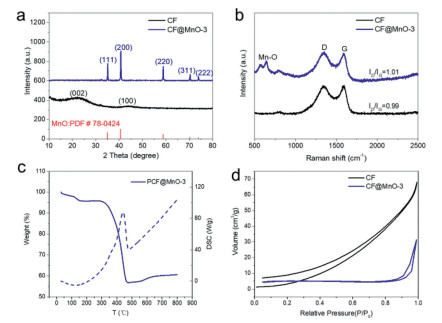
The structure and composition characterization of CF and CF@MnO-3 were further examined by X-ray diffraction (XRD) shown in Fig. 1a. Two broad peaks at 22.3° and 43.8°/2θ are observed in CF, which are corresponding to (002) and (100) bands, respectively, revealing that the carbon is almost amorphous [10]. In contrast, CF@MnO-3 displays five diffraction peaks at 35°, 40°, 59°, 70° and 73°/2θ, which are assigned to the crystal faces of (111), (200), (220), (311) and (222) of tetragonal MnO (JCPDS No. 06-0592), respectively [34-36]. The diffraction peak of CF in CF@MnO-3 is not obvious because the intensity of CF is relatively delicate compared to that of CF@MnO-3 composite material. Raman spectra were captured to further confirm the structure of CF and CF@MnO-3 (Fig. 1b), in which obvious bands centered at 1342 and 1591 cm−1 are allocated to the disordered carbon (D band) and the ordered graphitic carbon (G band), respectively [37]. Typically, D band is featured with structural defects of carbons and G band is originated from sp2 hybridization of carbons. It is well known that the ratio of the integrated areas of the D band and G band (ID/IG) manifests the order degree of carbon materials [38]. The ID/IG values of CF and CF@MnO-3 are estimated to be 0.99 and 1.01, respectively, indicating comparable structure orders of carbons in both samples. In addition, a band at 646 cm−1 is attributed to the characteristic Raman band of Mn-O in CF@MnO-3, confirming the existence of MnO [39], consistent with the XRD results.

|
Download:
|
| Fig. 1. (a) XRD patterns of the CF powders and CF@MnO-3 composite. (b) Raman spectra of the CF powders and CF@MnO-3 composites. (c) TG/DSC curve of the decomposition of CF@MnO-3 composite (Atmosphere: air, heating rate: 10 ℃/min). (d) Nitrogen sorption isotherms of CF and CF@MnO-3 composite. | |
The thermogravimetric analysis (TG/DSC) of CF@MnO-3 was conducted in air to estimate the weight of MnO in CF@MnO-3 (Fig. 1c), showing a distinct endothermic peak at 445 ℃ accompanying a significant thermal weight loss, which is caused by oxidation of carbon at elevated temperatures. Notably, as the temperature increases from 550 ℃ to 650 ℃, a slight increase in the TG curve is observed, which is caused by oxidation of MnO to form high-valence manganese compounds. The TG curve shows that the content of MnO retains 56.8% after 800 ℃. Nitrogen physisorption measurements were carried out at 77 K to analyze the textural characteristics of CF and CF@MnO-3 (Fig. 1d), exhibiting the prominent type-ІІІ isotherms. The surface area of CF is 13.9 m2/g with a pore volume of 0.097 cm3/g, whereas the surface area of CF@MnO is 15.5 m2/g with a pore volume of 0.048 cm3/g. Therefore, after loading MnO the specific surface area of CF does not change significantly, whereas the pore volume decreases to half of that of CF, indicating that the loaded MnO nanoparticles occupy or fill into a part of macro-/micropores of CF.
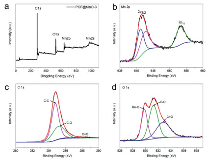
The XPS analysis was conducted to investigate the valence and electronic state of Mn on the surface of CF@MnO-3 (Fig. 2a). The predominant peaks at about 284.2, 531.6, 641.0 and 976 eV are assigned to C 1s, O 1s, Mn 2p and Mn 2s, respectively [40]. The Mn 2p spectrum shows two peaks of Mn 2p3/2 and Mn 2p1/2 located at 641.2 and 653.1 eV (Fig. 2b), respectively, attributing to the level splitting of Mn ions, resulting in energy difference of 11.9 eV, which confirms the main existence of Mn(II) in the CF@MnO-3 [23]. The XPS spectrum of C 1s shows two deconvoluted peaks at 284.7, 285.3 eV (Fig. 2c), assigned to C-C and C-O bonds, respectively. The O 1s spectrum shows three main peaks at 530.0, 531.4 eV and 532.8 eV, which are attributed to Mn-O, C-O and O-C=O bonds (Fig. 2d), respectively, indicating that O atoms are bound with Mn and C atoms [41].

|
Download:
|
| Fig. 2. (a) XPS spectra of CF@MnO-3 composite: survey spectrum. High-resolution XPS spectra of (b) Mn 2p, (c) O 1s, (d) C 1s. | |
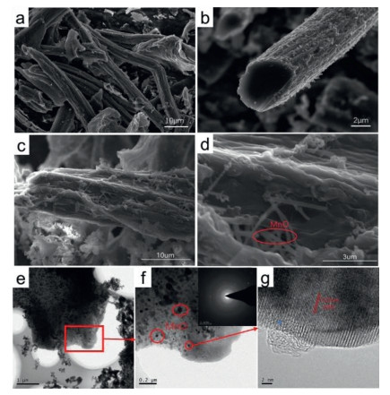
The morphology and microstructure of the CF and CF@MnO-3 samples were investigated by scanning electron microscopy (SEM) and transmission electron microscopy (TEM). It shows that the sample of CF is twisting and macro-porous (Figs. 3a and b). Apparently, the surface of carbon fibers in CF@MnO-3 is rough and covered by MnO nanowires after loading MnO (Figs. 3c and d). The TEM images clearly show the uniform dispersion of MnO nanoparticles embedded in the CF (Figs. 3e and f). The diffraction rings obtained from selected-area electron diffraction (SAED) pattern (inset in Fig. 3f) demonstrate that polycrystalline MnO nanoparticles are highly dispersed in CF@MnO-3, similar to the reported MnO quantum dots [42]. In the HRTEM image of CF@MnO-3 (Fig. 3g), the lattice spacing is measured to be about 0.22 nm, corresponding to the (200) interplanar distance of the MnO phase [41]. These results reveal that the MnO nanoparticles are highly distributed in the CF to obtain a CF@MnO composite, consistent with the above XRD, Raman and XPS results. The carbon fiber skeletons can provide superior merits and facilitate fast electron transport and lithium ions migration, the existence of inner space for carbon fiber can also facilitate the in-situ growth of MnO on the surface of carbon fiber and can accommodate the volume changes of MnO during repeated charge/discharge processes, while the CF@MnO-3 composite has many advantages as a negative electrode material for LIBs.

|
Download:
|
| Fig. 3. SEM images of (a, b) CF, (c, d) CF@MnO-3, (e, f) TEM images and (g) HRTEM image of CF@MnO-3 composite (inset in f: SAED pattern). | |
Fig. 4a shows the CV curves for three cycles of CF@MnO composites with different proportions of MnO. It can be seen that the discharge curve exhibits a weak cathode reduction peak between 0.7 V and 0.8 V, which is caused by the formation of SEI film during the first lithium intercalation process. The curve shows a reduction peak around 0.2 V, due to the reduction of manganese oxide to metallic manganese [43]: MnO + 2Li+ + 2e− → Mn + Li2O. Apparently, the main cathodic peak of the CF@MnO sample shifts to about 0.3-0.4 V in the 2nd and 3rd scan, indicating that the lithiation voltage is higher than that in the first cycle (~0.2 V), which is primarily caused by the enhanced kinetics of the CF@MnO electrode arising from the microstructure alteration and formation of Li2O and metal Mn after the first lithiation process. The peak located at 1.26 V corresponds to the Li desorption in nanopores and oxidation of manganese [44]: Mn + Li2O → MnO + 2Li+ + 2e−. The peak voltage of the cathode is close to 0 V during the discharge process and the apparent anode peak of 0.1 V during charging corresponds to Li adsorption and desorption on both sides of the nanopore walls, respectively.

|
Download:
|
| Fig. 4. (a) The 1st, 2nd and 3rd cycle profiles of CVs for various CF and CF@MnO samples at a sweep rate of 0.1 mV/s. (b) Charge/discharge voltage profiles at 50 mA/g, (c) charge/discharge rate performance at different current densities (d) and cycling stability at 100 mA/g for various CF@MnO samples (black, red, blue, magenta represent CF, CF@MnO-1, CF@MnO-2, CF@MnO-3, respectively). | |
The initial galvanostatic charge/discharge curves for different CF@MnO composites and CF at a current density of 50 mA/g are displayed in Fig. 4b. A steady stage around 0.2 V in the discharge branches and around 1.2 V in the charge branches of CF@MnO composites is observed, agreeing well with the CV results. The initial discharge capacities of CF, CF@MnO-1, CF@MnO-2 and CF@MnO-3 are approximately 583, 718, 904 and 923 mAh/g, respectively, and the charge capacities are 367, 433, 481 and 514 mAh/g with coulombic efficiency around 63%, 60%, 51% and 55%, respectively. It can be seen that the capacity of CF@MnO-3 is higher than those of CF, CF@MnO-1 and CF@MnO-2, which is ascribed to the increased proportions of loaded MnO and superior lithium-ion storage capacity. However, the CF@MnO-3 delivers the highest irreversible capacity because the increased amount of MnO leads to more irreversible lithium-ion consumptions during the initial lithiation process.
Fig. 4c shows the rate performance of CF and CF@MnO composites. As expected, CF@MnO-3 exhibits the superior specific capacities of 404, 352, 311, 266, 255 and 258 mAh/g at current densities of 100, 200, 400, 800, 1000 and 2000 mA/g, respectively. After 10 cycles at the current density of 2000 mA/g, the charge current density was gradually reduced to 100 mA/g, and the CF@MnO-3 delivers increased capacities from 272 mAh/g to 734 mAh/g, which can be considered by the electrolyte infiltration and electrode material. The above results show that the rate performance of CF is greatly improved after combination with MnO. It is speculated that the MnO nanoparticles embedded on the CF may be activated deeply after repeated cycling at large current densities resulting in enhanced lithium-ion storage capacity. Also, the synergic effect between CF and MnO may contribute to the improvement of the electrochemical performances. Fig. S2 (Supporting information) shows the charge and discharge curves of CF and CF@MnO composites at current densities of 50, 100, 200, 400, 800, 1000 and 2000 mA/g, respectively. It can be seen that the charge and discharge curves of the CF@MnO composites exhibit similar shapes, all of which have obvious slopes and capacity deterioration with increasing of the current density, suggesting that the CF@MnO composites display the same mechanism of lithium de-/intercalation. In contrast, the CF delivers a considerable capacity (235 mAh/g) at a potential of approaching 0 V when the current density is 50 mA/g. Therefore, graver decays are observed for CF at elevated current densities due to increasing electrochemical polarizations prevailing in universal electrodes.
Fig. 4d shows the cycling performance of CF and CF@MnO composites at a current density of 100 mA/g. The CF@MnO-3 exhibits the highest specific capacity of 522.8 mAh/g after 200 cycles. The capacity retentions of CF, CF@MnO-1, CF@MnO-2 and CF@MnO-3 are 60.2%, 51.0%, 73.6% and 78% with coulombic efficiency around 100% (Table S1 in Supporting information), respectively, indicating that the cycling performance of CF@MnO is steadily improved with the increase of MnO proportion. This result further confirms the advantages of CF@MnO as anode materials. Fig. S3 (Supporting information) displays the Nyquist plots and the equivalent circuit diagram of CF@MnO composites, in which the EIS map consists of a compressed semicircle and a diagonal line. The depressed semicircle in the high-frequency region represents the transfer impedance of charge passing through the electrode/electrolyte interface (Rct), and the linear Warburg impedance (ZW) in the low-frequency region represents the diffusion of lithium ions in the electrode material [45, 46]. The values of the R for CF@MnO-1, CF@MnO-2 and CF@MnO-3 electrode was 72.02, 69.92 and 63.97 Ω, respectively. The CF@MnO samples exhibit roughly approximate Rct values, which have a comparable effect on the rate performance of electrodes, in consistence with the charge/discharge results (Fig. 4b).
In summary, pine-derived CF@MnO composites were prepared as the anode materials for lithium-ion battery. It is demonstrated that the MnO nanoparticles are uniformly embedded on CF to construct the desired microstructure. Compared with the wood-derived carbon fibers, the CF@MnO composites show decreasing pore volumes resulting from the generation of MnO nanoparticles on macro-/micropores of carbon fibers. The carbon fiber skeletons facilitate fast electron transport and lithium ions migration, which can also accommodate the volume changes of MnO during repeated charge/discharge processes. Among all the CF@MnO composite materials, CF@MnO-3 composite (the weight ratio of 1:2) exhibits larger capacity, superior rate and cycling performance. Therefore, the CF@MnO composites show considerable potential as a sustainable anode for LIBs.
Declaration of competing interestThe authors declare that they have no interests could have appeared to influence the work reported in this manuscript.
AcknowledgmentsThis research was financially supported by the Hunan Provincial Natural Science Foundation of China (No. 2020JJ2058), Forestry science and technology innovation of Hunan Province (No. XLK202107-3), Scientific Research Foundation of Hunan Provincial Education Department (No. 18A159), Scientific Research Foundation of Central South University of Forestry and Technology (Nos. 104–0452, 2018YC003) and the National Natural Science Foundation of China (No. 52073064).
Supplementary materialsSupplementary material associated with this article can be found, in the online version, at doi: 10.1016/j.cclet.2021.06.088.
| [1] |
B. Guo, X. Yu, X. Sun, et al., Energy Environ. Sci. 7 (2014) 2220-2226. DOI:10.1039/C4EE00508B |
| [2] |
N.C. Gallego, C.I. Contescu, H.M. Meyer, et al., Carbon 72 (2014) 393-401. DOI:10.1016/j.carbon.2014.02.031 |
| [3] |
S.R. Sivakkumar, J.Y. Nerkar, A.G. Pandolfo, Electrochim. Acta 55 (2010) 3330-3335. DOI:10.1016/j.electacta.2010.01.059 |
| [4] |
W.E. Tenhaeff, O. Rios, K. More, A. McGuire, Adv. Funct. Mater. 24 (2014) 86-94. DOI:10.1002/adfm.201301420 |
| [5] |
J. Jiang, J.H. Zhu, W. Ai, et al., Energy Environ. Sci. 7 (2014) 2670-2679. DOI:10.1039/C4EE00602J |
| [6] |
L. Wang, Z. Schnepp, M.M. Titirici, J. Mater. Chem. A 1 (2013) 5269-5273. DOI:10.1039/c3ta10650k |
| [7] |
J. Hou, C. Cao, F. Idrees, X. Ma, ACS Nano 9 (2015) 2556-2564. DOI:10.1021/nn506394r |
| [8] |
R.R. Gaddam, D. Yang, R. Narayan, et al., Nano Energy 26 (2016) 346-352. DOI:10.1016/j.nanoen.2016.05.047 |
| [9] |
P. Liu, Y.M. Li, Y.S. Hu, et al., J. Mater. Chem. A 4 (2016) 13046-13052. DOI:10.1039/C6TA04877C |
| [10] |
K. Hong, L. Qie, R. Zeng, et al., J. Mater. Chem. A 2 (2014) 12733-12738. DOI:10.1039/C4TA02068E |
| [11] |
Y. Wang, C. Wang, Y. Wang, H. Liu, Z. Huang, ACS Appl. Mat. Interfaces 8 (2016) 18860-18866. DOI:10.1021/acsami.6b04774 |
| [12] |
X. Zhang, J. Hu, X. Chen, et al., J. Porous Mater. 26 (2019) 1821-1830. DOI:10.1007/s10934-019-00781-3 |
| [13] |
C. Ling, F. Mizuno, Phys. Chem. Chem. Phys. 16 (2014) 10419-10424. DOI:10.1039/C4CP01045K |
| [14] |
Y. Huang, K. Li, G. Yang, et al., Small 14 (2018) 1703969. DOI:10.1002/smll.201703969 |
| [15] |
Z. Wang, L. Qie, L. Yuan, et al., Carbon 55 (2013) 328-334. DOI:10.1016/j.carbon.2012.12.072 |
| [16] |
H. Zhu, J. Zhang, R. Yanzhang, et al., Adv. Mater. 27 (2015) 4752-4759. DOI:10.1002/adma.201501969 |
| [17] |
H. Wang, Z. Wu, F. Meng, et al., ChemSusChem 6 (2013) 56-60. DOI:10.1002/cssc.201200680 |
| [18] |
Y.S. Yun, V. Le, H. Kim, et al., J. Power Sour. 262 (2014) 79-85. DOI:10.1016/j.jpowsour.2014.03.084 |
| [19] |
X. Wang, G. Li, F.M. Hassan, et al., Nano Res. 15 (2015) 746-754. |
| [20] |
H. Hou, L. Shao, Y. Zhang, et al., Adv. Sci. 4 (2017) 1600243. DOI:10.1002/advs.201600243 |
| [21] |
L. David, G. Singh, J. Phys. Chem. C 118 (2014) 28401-28408. DOI:10.1021/jp5080847 |
| [22] |
H. Li, L. Jiang, Q. Feng, et al., Energy Stor. Mater. 17 (2018) 157-166. |
| [23] |
Z. Xiao, G. Ning, Z. Yu, et al., Nanoscale 11 (2019) 8270-8280. DOI:10.1039/c8nr10294e |
| [24] |
L. Zhang, D. Ge, G. Qu, et al., Nanoscale 9 (2017) 5451-5457. DOI:10.1039/C7NR01425B |
| [25] |
J. Fei, Y. Cui, J. Li, et al., Chem. Commun. 53 (2017) 13165-13167. DOI:10.1039/C7CC06945F |
| [26] |
M. Hu, Y. Jiang, W. Sun, et al., ACS Appl. Mater. Interfaces 6 (2014) 19449-19455. DOI:10.1021/am505505m |
| [27] |
M. Gu, A. Kushima, Y. Shao, et al., Nano Lett. 13 (2013) 5203-5211. DOI:10.1021/nl402633n |
| [28] |
B. Qu, C. Ma, G. Ji, et al., Adv. Mater. 26 (2014) 3854-3859. DOI:10.1002/adma.201306314 |
| [29] |
H. Hou, M. Jing, Z. Huang, et al., ACS Appl. Mater. Interfaces 7 (2015) 19362-19369. DOI:10.1021/acsami.5b05509 |
| [30] |
G. Zhu, Y. Du, Y. Wang, et al., J. Electroanal. Chem. 688 (2013) 86-92. DOI:10.1016/j.jelechem.2012.07.035 |
| [31] |
G. Hu, K. Zhong, R. Yu, et al., J. Mater. Chem. A 8 (2020) 13285-13291. DOI:10.1039/d0ta00540a |
| [32] |
G. Hu, R. Yu, Z. Liu, et al., ACS Appl. Mater. Interfaces 13 (2021) 3391-3398. |
| [33] |
H. Jiang, Y. Hu, S. Guo, et al., ACS Nano 8 (2014) 6038. DOI:10.1021/nn501310n |
| [34] |
J. Wang, H. Yang, L. Kang, et al., J. Solid State Chem. 264 (2018) 134-140. DOI:10.1016/j.jssc.2018.05.017 |
| [35] |
W. Zhang, J. Sheng, J. Zhang, et al., J. Mater. Chem. A 4 (2016) 16936-16945. DOI:10.1039/C6TA06933A |
| [36] |
Y. Xia, Z. Xiao, X. Dou, et al., ACS Nano 7 (2013) 7083-7092. DOI:10.1021/nn4023894 |
| [37] |
K. Eunae, Yoon, et al., Adv. Funct. Mater. 21 (2011) 4349-4357. DOI:10.1002/adfm.201101123 |
| [38] |
Y. Qin, H. Tang, K. Chang, et al., Nanotechnology 30 (2018) 015403. |
| [39] |
C. Pardanaud, C. Martin, P. Roubin, et al., Diam. Relat. Mater. 34 (2013) 100-104. DOI:10.1016/j.diamond.2013.02.009 |
| [40] |
H. Li, L. Jiang, Q. Feng, et al., Energy Storage Mater. 17 (2018) 157-166. |
| [41] |
Y. Guo, T. Feng, J. Yang, et al., Nanoscale 11 (2019) 10763-10773. DOI:10.1039/c9nr02206f |
| [42] |
J. Wang, L. Wei, J. Chen, et al., Electrochim. Acta 188 (2016) 210-217. DOI:10.1016/j.electacta.2015.11.128 |
| [43] |
H. Xia, H. Caiyun, B. Li, et al., Adv. Funct. Mater. 25 (2014) 627-635. DOI:10.1002/pc.22704 |
| [44] |
A. Funabiki, M. Inaba, Z. Ogumi, J. Power Sour. 68 (1997) 227-231. DOI:10.1016/S0378-7753(96)02556-6 |
| [45] |
T. Doi, K. Miyatake, Y. Iriyama, et al., Carbon 42 (2004) 3183-3187. DOI:10.1016/j.carbon.2004.08.005 |
| [46] |
Z. Ogumi, T. Abe, T. Fukutsuka, et al., J. Power Sour. 127 (2004) 72-75. DOI:10.1016/j.jpowsour.2003.09.009 |