 2022, Vol. 33


b Center of Materials Science and Optoelectronics Engineering, University of Chinese Academy of Sciences, Beijing 100049, China;
c State Key Laboratory of Precision Spectroscopy, School of Physics and Electronic Science, East China Normal University, Shanghai 200241, China;
d School of Physical Science and Technology, ShanghaiTech University, Shanghai 200031, China;
e XXL - The Extreme Optoelectromechanics Laboratory, School of Physics and Electronic Science, East China Normal University, Shanghai 200241, China
Automated synthesis realized by microfluidic chips has been recognized to be an important part of next-generation chemical engineering [1]. This technology saves people from time-consuming lab work, therefore, has drawn much attention both in academic and industry fields [1-17]. Multiphase reactions have been demonstrated to be possible and are usually enhanced inside the microfluidic chips [18-24]. However, the solid-liquid reactions remain rare [18-24]. One reason is that the channels may be easily blocked by the solid-state reactants. Compared with the gas phase and liquid phase reactants, solid phase reactants have their own advantages such as low cost and easy for storage. Particularly, in some cases, solid phase is the only available form of the reactants. Therefore, despite the difficulty in performing solid-liquid reactions, it is necessary to find a way to realize high-efficiency and scalable solid-liquid synthesis in the microfluidic chips which is an essential step towards automated solid-liquid synthesis.
So far, a main challenge is that the intrinsic narrow channels of the microfluidic chips are not suitable for solid-liquid reaction, because the solid phase reactants with large volumetric fraction can increase viscosity of the fluid which hinders fast passage and uniform mixing in the microreactor. One might expect that scaling-up of the microfluidic channels can solve this problem. However, simply extending the scale of the microfluidic channels is insufficient. It would be necessary to alternate the flow from two-dimensional (2D) to three-dimensional (3D) type which can enhance the mixing effect and accelerate the flow rate [25-27]. Such a 3D-type shear flow can be realized by well-designed 3D channel structure which, however, is very difficult to be fabricated by planar manufacturing technologies, such as injection molding, hot embossing and casting. Alternatively, femtosecond laser direct writing (FLDW) extends the microfluidic structures from 2D to 3D geometries, which allows for integration of different types of 3D functional components in a straightforward packaging-free manner [28, 29].
In this work, we designed a multifunctional 3D microfluidic chip and fabricated it using femtosecond laser assisted chemical wet etching technique [30-32]. The 3D structures are expected to produce 3D shear flows inside the chip, enabling the passage acceleration of the solid-state reactants and the increase in flow rates. The key to succeed in solid-liquid reactions is to enlarge the contact area of fluids while keeping a high throughput. We specifically designed a new structure in this work. As illustrated in Fig. 1a, the designed chip consists of two parts. The reactants enter the chip and flow through the first segment (S1) and second segment (S2) of the chip. The S1 consists of periodic 3D structure units which can squeeze the incoming fluids in the vertical direction (Fig. 1b). As a result, the reactant fluids flowing vertically are split and reorganized into multiple fluids in the horizontal direction. In this process, the contact area between the two reactant fluids would be dramatically increased, improving the mixing efficiency. Furthermore, the convection effect induced by the sheer force effect between two adjacent sub-fluids will further increase the mixing of the two reactants. The mixing performance of the designed structure composed of mixing units was numerically simulated by solving the microfluidic incompressible Navier-Stokes and convection diffusion equations. The simulations result in Fig. 1b shows an excellent mixing effect thanks to the working mechanism described above. Likewise, S2 consists of 5 × 6 2D mixing units arranged periodically in the transverse direction. The detailed structure of the unit can be seen in Fig. 1c. The outlet width of each unit is sharply narrowed to 300 µm, which will not create a blockage of solids, yet enables a variation in flow rate that enhances mixing. In addition, each unit has a baffle in the center to create convection and turbulence which will further improve the mixing effect of the reactants. It should be noted that the mixing unit structure of the the designed microfluidic chip is flat, which facilitates heat dissipation in chemical reactions. The chip was fabricated by a ultrafast laser micromachining system as schematically illustrated in Fig. S1a (Supporting information). After the femtosecond laser irradiation, the substrate was immersed in a solution of potassium hydroxide (KOH) for selectively removing the material exposed to the irradiation of the laser pulses. The procedures of the laser fabrication were schematically illustrated in Fig. S1b (Supporting information). The photographs of the fabricated microfluidic chip and the detailed mixing units in S1 and S2 are shown in Fig. 1d. The enlarged image of the microstructure and 3D details of the two units are shown in Fig. S2 (Supporting information).

|
Download:
|
| Fig. 1. (a) Structure illustration of the microfluidic chip. (b) Structural details and simulation the first segment (S1). (c) Structural details and simulation the second segment (S2). (d) Digital photo of the microfluidic chip. | |
The model reaction is synthesis of gadopentetate dimeglumine which is the most widely used magnetic resonance imaging (MRI) contrast agent [33-36]. Developing an automated flow synthesis system for gadopentetate dimeglumine can offer options for medical requirements in remote areas. The cost of the gadolinium-containing chemical varies greatly from oxide to nitrate. The gadolinium oxide is of a cheaper price and easier to be stored than the gadolinium nitrate, therefore is suitable for distributed synthesis in remote areas. However, because of the insolubility of the gadolinium oxide in water, the reaction is a solid-liquid reaction in the microfluidic chip. Such a solid-liquid phase reaction is suitable for evaluating practical performance of our designed microreactor.
Suspension of the solid-state reactants was pumped through the microfluidic chips to check whether the solid-state reactants could pass through without causing clogging of the fluid. Before testing, the viscosity of the suspension was characterized (Fig. S3 in Supporting information). During the test, the solid (gadolinium oxide) to liquid (water) ratio (in mass) was controlled in a range from 1:100 to 100:100. The viscosity of the suspension was increased with the solid to liquid ratio. A shear thinning behavior was observed in all the cases, matching with the typical fluid property of the solid-liquid mixture. Then, the suspension was passed through the microfluidic chip at 25 ℃. The set and the experimental flow rates were compared in Fig. 2. The set flow rates and the experimental flow rates are almost the same in all the tests. Increasing the solid to liquid ratio did not change the relationship between the two rates. This confirms that the solid phase reactants can pass through our microfluidic chip efficiently during synthesis, demonstrating that the specific structural design of the microfluidic channel works well for the mixed solid-liquid fluid.

|
Download:
|
| Fig. 2. Comparison of the flow rate between the set value (red) and experimental data (blue). | |
We assembled a flow reaction system by using this microfluidic chip with UV-vis spectrometer. Peristaltic pumps were employed to drive the flow under control of computer (Fig. 3a). The reaction among gadolinium oxide, diethylene triamine pentaacetic acid (DTPA), and N-methylglucamine is carried under heating at 85 ℃ as illustrated in Fig. 3b. Gadopentetate dimeglumine is the product, and water is the only byproduct. Typically, equivalent amount of gadolinium oxide, diethylene triamine pentaacetic acid (DTPA), and N-methylglucamine were mixed in water to form solid-liquid suspension. The molar ratio of the three reactants was kept to be 1:2:4. Scanning electron microscopy and optical microscopy present that the gadolinium oxide is composed of particles with micron sizes (2~10 µm in size) (Figs. S4 and S5 in Supporting information). The suspension was characterized by digital camera and optical microscopy as well (Figs. S6 and S7 in Supporting information). No significant dissolution of the particles can be observed at room temperature. After pumping the suspension into the microfluidic chip which was under heating at 85 ℃ in water bath, the product was collected through filtering, then got dried under vacuum at 100 ℃ for 8 h.

|
Download:
|
| Fig. 3. (a) Schematic illustration for automated flow synthetic system. (b) Schematic illustration for chemical reaction happens in the flow synthetic system. | |
Fig. S8 (Supporting information) shows the UV-vis spectrum of the obtained sample in water solution. The absorption peak centered at 275 nm is assigned to be metal-to-ligand charge transfer, suggesting successful coordination between Gd3+ and the ligand. Fig. S9 (Supporting information) illustrates infrared (IR) spectrum of the harvested product [37-39]. The absorption peaks at 3350 cm-1 and 2900 cm-1 correspond to the stretching vibration of -OH and C-H bonds of methylene, respectively. The intense absorption peaks at 1600 cm-1 and 1409 cm-1 are attributed to the symmetrical and asymmetrical stretching vibrations of C=O bond of -COOH group. And these two absorption peaks move towards lower wave number which may be rationalized to the coordination of COO- with Gd3+. The absorption peaks at 1093 cm-1 and 1040 cm-1 correspond to the stretching vibration of C-OH and C-N bond of N-methylglucamine. High performance liquid chromatography (HPLC) confirms the deduction of the UV-vis spectrum and FTIR data (Fig. S10 in Supporting information). The obtained gadopentetate dimeglumine was tested in magnetic resonance imaging (MRI) (Fig. S11 in Supporting information). The gadopentetate dimeglumine solution was injected from the tail into a rat. After 10 min, image taken from the bladder showed enhanced contrast, which suggested that the gadopentetate dimeglumine synthesized by this flow system successfully worked in the animal test.
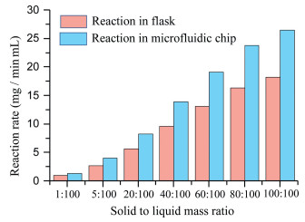
The reaction rate of the flow synthetic system was automatically evaluated by the in-line UV-vis spectrum. Linear relationship between the concentration of the gadopentetate dimeglumine and the absorption at 275 nm was established in Fig. S12 (Supporting information). This linear relationship is employed for in-line analysis of the reaction rate of the gadopentetate dimeglumine. When the solid to liquid mass ratio was 5:100, the reaction rate in the flow synthetic system was 4.02 mg mL-1 min-1 (Fig. 4). In comparison, the reaction was also carried in the round-bottom flask system (1 L in volume) as well. The typical product obtained in the flask reactor was characterized by UV-vis spectrometer and IR spectrometer as shown in Figs. S13 and S14 (Supporting information). The data confirms that the product synthesized in the round-bottom flask is the same as the molecules synthesized in the microfluidic chips. In the round-bottom flask with similar concentration of the reactants, the reaction rate was generally smaller. For instance, when the solid to liquid ratio was 5:100, the reaction rate in flask was about 2.74 mg mL-1 min-1 which is less than the reaction rate in the microfluidic chip (4.02 mg mL-1 min-1). This trend of the rate difference is confirmed in a wide range of the solid to liquid mass ratios (1:100~100:100). The reaction rates in the microfluidic chips are higher than in the flasks.

|
Download:
|
| Fig. 4. Comparison of the reaction rates between the flow synthetic system and the flask synthetic system. | |
The enhancement of the yielding rate relates to the enhanced mass diffusion and collision in the microfluidic chip. This agrees with the mixing characteristic shown in Fig. 1. The split and reorganization of the solid-liquid fluid in the microfluidic chip can induce convection effect among the adjacent sub-fluids (Fig. 1b). The baffle in each unit shown in Fig. 1c can also create convection and turbulence. The convection and turbulence effects enhance collision among the solid reactant and the molecular reactant. The products can also be taken away from the solid reactant, making the unreacted surface to be exposed fast. Apparently, this microfluidic chip can solve the obstacle in solid-liquid phase reactions in the microreactors. To further confirm the significance of the microfluidic chip reported in this work, we employed another microfluidic chip with a different micro-structure as shown in Fig. S15 (Supporting information). Different from the microfluidic chip shown in Fig. 1, mixing in this microfluidic channel based on splitting, routing, and reorganizing of the fluid in a mixing unit [17]. The number of microstreams is basically increased to 4 times by a unit, enabling high-efficiency mixing. The reaction rate in this microfluidic chip was tested and compared in Fig. S16 (Supporting information). It turns out that the reaction rate of the microfluidic chip is smaller, confirming that the undulating structure and the convective shear force in the microfluidic chip shown in Fig. 1 is highly important for solid-liquid reaction.
In summary, we presented a designed 3D microfluidic chip and fabricated it using femtosecond laser micromachining technology. The 3D shear flow induces by the designed mixing units greatly enhanced the mixing efficiency and accelerate movement of the solid-liquid phase mixture inside the microreactor. As a result, a solid-liquid reaction was realized in this unique microfluidic chip to synthesize gadopentetate dimeglumine, which greatly expanded the availability of the solid-state reactants. The flow system built up in our work showed much higher reaction rates than the system using round-bottom flask reactors, indicating that the 3D microfluidic chip realized by femtosecond laser fabrication has benefits in terms of improving the mixing efficiency and allowing the track of high-throughput synthesis.
Declaration of competing interestThe authors declare no conflict of interest.
AcknowledgmentsThe work is supported by National Natural Science Foundation of China (No. 11674340); Key Project of the Shanghai Science and Technology Committee (No. 18DZ1112700).
| [1] |
C.W. Coley, D.A. Thomas, J.A.M. Lummiss, et al., Science 365 (2019) 557. |
| [2] |
M. Baumann, I.R. Baxendale, S.V. Ley, C.D. Smith, G.K. Tranmer, Org. Lett. 8 (2006) 5231-5234. DOI:10.1021/ol061975c |
| [3] |
A.C. Bedard, A. Adamo, K.C. Aroh, et al., Science 361 (2018) 1220. DOI:10.1126/science.aat0650 |
| [4] |
Z.S. Campbell, F. Bateni, A.A. Volk, K. Abdel-Latif, M. Abolhasani, Part. Part. Syst. Charact. 37 (2020) 2000256. DOI:10.1002/ppsc.202000256 |
| [5] |
R.W. Epps, K.C. Felton, C.W. Coley, M. Abolhasani, Lab Chip 17 (2017) 4040-4047. DOI:10.1039/C7LC00884H |
| [6] |
D.E. Fitzpatrick, T. Maujean, A.C. Evans, S.V. Ley, Angew. Chem. Int. Ed. 57 (2018) 15128-15132. DOI:10.1002/anie.201809080 |
| [7] |
A. Isozaki, J. Harmon, Y. Zhou, et al., Lab Chip 20 (2020) 3074-3090. DOI:10.1039/d0lc00521e |
| [8] |
C. Mateos, M.J. Nieves-Remacha, J.A. Rincon, React. Chem. Eng. 4 (2019) 1536-1544. DOI:10.1039/c9re00116f |
| [9] |
A.J. Mijalis, D.A. Thoma, M.D. Simon, et al., Nat. Chem. Biology 13 (2017) 464. DOI:10.1038/nchembio.2318 |
| [10] |
B.J. Reizman, K.F. Jensen, Acc. Chem. Res. 49 (2016) 1786-1796. DOI:10.1021/acs.accounts.6b00261 |
| [11] |
B.J. Reizman, Y.M. Wang, S.L. Buchwald, K.F. Jensen, React. Chem. Eng. 1 (2016) 658-666. DOI:10.1039/C6RE00153J |
| [12] |
L. Xie, D.Y. Zhao, Chin. Chem. Lett. 31 (2020) 2395-2400. DOI:10.1016/j.cclet.2020.03.022 |
| [13] |
W. Zhan, M. Tong, L. Ji, et al., Chin. Chem. Lett. 30 (2019) 973-976. DOI:10.1016/j.cclet.2019.01.006 |
| [14] |
Y. Wu, W.Q. Chen, Y.Q. Zhao, H.R. Piao, Chin. Chem. Lett. 26 (2015) 334-338. DOI:10.5325/style.49.3.0334 |
| [15] |
Y. Xin, S. Peng, J.X. Chen, Z.J. Yang, J.Y. Zhang, Chin. Chem. Lett. 31 (2020) 1448-1461. DOI:10.1016/j.cclet.2019.09.054 |
| [16] |
Y. Wang, L.J. Li, L.T. Yan, et al., Chin. Chem. Lett. 29 (2018) 849-853. DOI:10.1016/j.cclet.2017.09.057 |
| [17] |
W. Li, Y. Li, W. Zhang, et al., Chin. Chem. Lett. 32 (2021) 1131-1134. DOI:10.1016/j.cclet.2020.09.039 |
| [18] |
F. Carraro, J.D. Williams, M. Linares-Moreau, et al., Angew. Chem. Int. Ed. 59 (2020) 8123-8127. DOI:10.1002/anie.202000678 |
| [19] |
K.S. Elvira, X.C.I. Solvas, R.C.R. Wootton, A.J. deMello, Nat. Chem. 5 (2013) 905-915. DOI:10.1038/nchem.1753 |
| [20] |
R.L. Hartman, Org. Proc. Res. Dev. 16 (2012) 870-887. DOI:10.1021/op200348t |
| [21] |
K.F. Jensen, AICHE J. 63 (2017) 858-869. DOI:10.1002/aic.15642 |
| [22] |
M.B. Plutschack, B. Pieber, K. Gilmore, P.H. Seeberger, Chem. Rev. 117 (2017) 11796-11893. DOI:10.1021/acs.chemrev.7b00183 |
| [23] |
J.H. Xu, S.W. Li, J. Tan, Y.J. Wang, G.S. Luo, Langmuir 22 (2006) 7943-7946. DOI:10.1021/la0605743 |
| [24] |
H. Xu, J. Tan, S.W. Li, G.S. Luo, Chem. Eng. J. 141 (2008) 242-249. DOI:10.1016/j.cej.2007.12.030 |
| [25] |
N. Bhattacharjee, A. Urrios, S. Kang, A. Folch, Lab Chip 16 (2016) 1720-1742. DOI:10.1039/C6LC00163G |
| [26] |
A.K. Au, W. Huynh, L.F. Horowitz, A. Folch, Angew. Chem. Int. Ed. 55 (2016) 3862-3881. DOI:10.1002/anie.201504382 |
| [27] |
K.C. Bhargava, B. Thompson, N. Malmstadt, Proc. Nat. Acad. Sci. U. S. A. 111 (2014) 15013-15018. DOI:10.1073/pnas.1414764111 |
| [28] |
K. Sugioka, Y. Cheng, Light Sci. Appl. 3 (2014) e149. DOI:10.1038/lsa.2014.30 |
| [29] |
K. Sugioka, Y. Cheng, K. Midorikawa, Appl. Phys. A 81 (2005) 1-10. DOI:10.1007/s00339-005-3225-1 |
| [30] |
Y. Bellouard, A. Said, M. Dugan, P. Bado, Optics Express 12 (2004) 2120-2129. DOI:10.1364/OPEX.12.002120 |
| [31] |
C. Hnatovsky, R.S. Taylor, E. Simova, et al., Appl. Phys. A 84 (2006) 47-61. DOI:10.1007/s00339-006-3590-4 |
| [32] |
W. Li, W. Chu, D. Yin, et al., Appl. Phys. A 126 (2020) 816. DOI:10.1007/s00339-020-04000-8 |
| [33] |
J. Lohrke, T. Frenzel, J. Endrikat, et al., Adv. Ther. 33 (2016) 1-28. DOI:10.1007/s12325-015-0275-4 |
| [34] |
A. Radbruch, L.D. Weberling, P.J. Kieslich, et al., Radiology 275 (2015) 783-791. DOI:10.1148/radiol.2015150337 |
| [35] |
M. Rohrer, H. Bauer, J. Mintorovitch, M. Requardt, H.J. Weinmann, Invest. Radiol. 40 (2005) 715-724. DOI:10.1097/01.rli.0000184756.66360.d3 |
| [36] |
P.S. Tofts, G. Brix, D.L. Buckley, et al., J. Magn. Reson. Imaging 10 (1999) 223-232. DOI:10.1002/(SICI)1522-2586(199909)10:3<223::AID-JMRI2>3.0.CO;2-S |
| [37] |
Y. Huang, H. Wu, T. Shao, et al., Chem. Eng. J. 339 (2018) 322-333. DOI:10.1016/j.cej.2018.01.071 |
| [38] |
T.M. Cheng, R. Li, Y.C.J. Kao, et al., Mater. Sci. Eng. C 114 (2020) 111064. DOI:10.1016/j.msec.2020.111064 |
| [39] |
G. Sun, J. Feng, F. Jing, F. Pei, M. Liu, J. Magn. Magn. Mater. 265 (2003) 123-129. DOI:10.1016/S0304-8853(03)00239-7 |