 2022, Vol. 33


b Jiangsu Province Engineering Laboratory of High Efficient Energy Storage Technology and Equipment, China University of Mining and Technology, Xuzhou 221116, China
The shortage of fossil energy has forced mankind to seek energy revolution. Compared with other energy sources, hydrogen (H2), as an ideal, clean and renewable energy with ultra-high calorific value of 122 kJ/g, has great advantages in preparation and application [1]. The traditional H2 production methods, mainly including water gas reforming and electrolysis of water, consume a large amount of fossil energy and cause pollution. In contrast, using semiconductors to produce H2 from solar energy is a clean and low-cost way [2, 3].
Various semiconductor photocatalysts have been explored and prepared to split water, but most of them cannot be used alone and require the participation of sacrificial agents. Moreover, the high-performance of most photocatalysts come from the deposition of precious metals, which undoubtedly increases the cost of photocatalytic H2 production [4-12]. Therefore, it is very necessary to develop a non-noble metal photocatalyst with high photocatalytic activity without the assistance of sacrificial agent.
Recently, hexagonal ZnIn2S4 (ZIS), a two-dimensional (2D) metal sulfide, is of great interest to researchers. Due to its suitable band gap, unique layered structure, good stability and low cost, ZIS has been considered as an ideal photocatalyst for H2 production [13-16]. However, there are still some disadvantages in ZIS, such as the slow charge transfer, easy recombination of electron-hole pairs, which limit its practical application [17-20]. Previous studies have reported that the coupling of suitable semiconductors to form heterojunctions can effectively improve the photocatalytic performance [21-25]. For example, Zhang et al. deposited MoS2 quantum dots (QDs) on the S vacancies of monolayered ZIS to realize the rapid transfer of photogenerated electrons from ZIS to MoS2, through the mutual bonding of Zn atoms nearby the S vacancy of ZIS with S atoms of MoS2 [26]. Wang et al. synthesized a cage-like hierarchical Co9S8@ZIS heterostructure for enhanced photocatalytic charge separation and transfer, improving the photocatalytic activity and stability [16]. Therefore, developing a suitable semiconductor material to couple with ZIS is an important strategy to improve the photocatalytic activity of ZIS.
In this work, we designed a hierarchical hollow NiS@ZIS heterostructure photocatalyst by growing two-dimensional ZIS ultra-thin nanosheets on hollow NiS nanospheres. NiS is a narrow bandgap (0.4–0.7 eV) semiconductor. When coupling with ZIS, the lower conduction band (CB)/valence band (VB) potential of NiS will be great for the separation and migration of charges. Meanwhile, this unique hierarchical hollow structure can not only provide larger surface area and more active sites but also extend the optical absorption, enhancing the utilization of visible light and boosting the separation and migration of photogenerated charges [27-31]. Based on these advantages, the prepared NiS@ZIS heterostructure photocatalyst exhibits high photocatalytic activity for splitting of water. In the absence of co-catalysts and sacrificial agents, the H2 evolution rate of NiS@ZIS reached 1.24 mmol g-1 h-1, which was 5.6 times higher than that of pure ZIS nanosheets. The charge transfer and photocatalytic reaction mechanism of NiS@ZIS heterostructure was proposed upon a series of spectroscopic and photoelectrochemical characterizations.
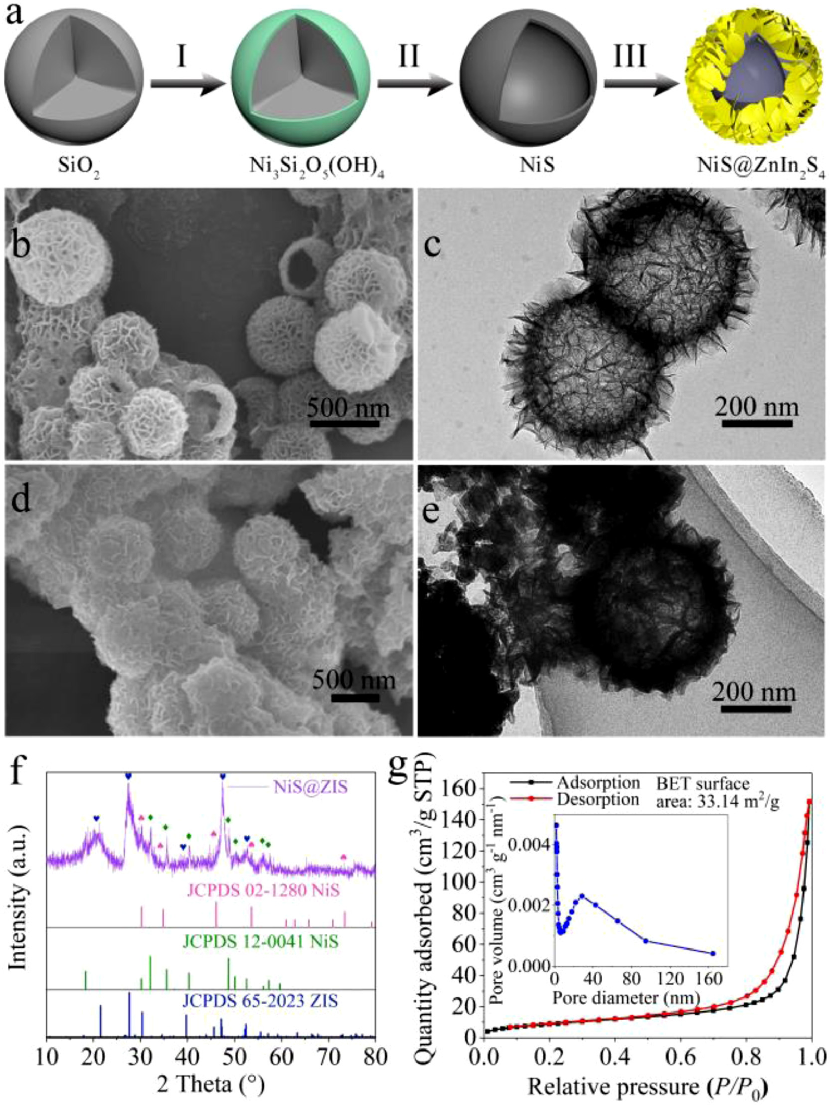
Fig. 1a illustrates the preparation process of hierarchical NiS@ZIS heterostructure. First, a nickel silicate (Ni3Si2O5(OH)4) coating was grown on the surface of SiO2 nanospheres in a hydrothermal reaction system containing SiO2, urea and nickel nitrate (Step I). Next, the Ni3Si2O5(OH)4 nanospheres were vulcanized by hydrothermal process, producing NiS hollow spheres (Step II). Finally, the hollow NiS@ZIS heterostructure was obtained by growing a layer of ZIS nanosheets on the surface of NiS under 80 ℃ of oil bath (Step III). In the experiment, SiO2 nanospheres were synthesized according to the reported method [32, 33]. The Powder X-ray diffraction (XRD) pattern is shown in Fig. S1a (Supporting information). The diffraction peak at 22.02° is consistent with the standard PDF card of SiO2 (JCPDS No. 29-0085). The field-emission scanning electron microscopy (FESEM) image in Fig. S1b (Supporting information) shows the smooth surface of SiO2 spheres with average diameter of 400 nm. Nickel silicate (Ni3Si2O5(OH)4) nanospheres were synthesized via a hydrothermal reaction [34], and XRD analysis indicates their successful formation (Fig. S2a in Supporting information). FESEM image shows that the morphology of Ni3Si2O5(OH)4 is uniform nanospheres coating with nickel silicate thin layer (Fig. S2b in Supporting information). The original spherical shape and size of the SiO2 templates are retained. To remove the SiO2 templates and vulcanize the nickel silicate, Ni3Si2O5(OH)4 nanospheres were dispersed in Na2S·9H2O solution, followed by a hydrothermal treatment at 160 ℃ [34]. After the sulfuration, the coating layer of nickel silicate was translated to NiS while the hollow structure was still retained. As shown in Fig. 1b, NiS nanospheres have an average diameter of 420 nm. The surfaces are composed of ultra-thin nanosheets. From the broken spheres, one can conclude that the obtained NiS possesses a hollow structure. The corresponding N2 sorption measurement confirms the presence of mesopores in NiS, with a specific surface area of 19.76 m2/g (Fig. S3 in Supporting information). XRD pattern in Fig. S4a identifies the formation of NiS mixed phase. All the diffraction peaks belong to the NiS rhomboid phase (β-NiS, JCPDS No. 12-0041) and NiS hexagonal phase (α-NiS, JCPDS No. 02-1280), consisting with the previous reports [35, 36]. Transmission electron microscopy (TEM) image further proves the hollow structure of NiS (Fig. 1c). The high-resolution TEM (HRTEM) image (Fig. S4b in Supporting information) exhibits clear crystal lattice fringe with an interlayer distance of 0.29 nm, corresponding to (101) crystal plane of NiS.

|
Download:
|
| Fig. 1. (a) Schematic illustration of the preparation process of hierarchical NiS@ZIS heterostructure: (I) hydrothermal reaction, (II) sulfidation reaction and (III) the growth of ZIS nanosheets. (b) FESEM and (c) TEM image of NiS nanospheres. (d) FESEM image, (e) TEM image, (f) XRD pattern, and (g) N2 sorption isotherms and BET surface area of NiS@ZIS composites. Inset is the corresponding pore size distribution curve. | |
Subsequently, ultra-thin ZIS nanosheets were grown on the surface of NiS nanospheres through a low temperature oil bath method. The mass ratio of NiS to ZIS in the composite is 1:x, which is denoted as NiS@ZIS 1-x (NiS@ZIS 1–8 is abbreviated as NiS@ZIS unless otherwise specified). In Figs. 1d and e, ZIS ultra-thin nanosheets are uniformly coated on the surface of NiS nanospheres. The composite remains the original spherical morphology with an average size of 500 nm. XRD pattern in Fig. 1f indicates that the composite includes the mixed phase of NiS and hexagonal ZIS, proving the successful preparation of NiS@ZIS. N2 sorption measurement confirms the unaltered mesopore structure in NiS@ZIS, with a much higher specific surface area of 33.14 m2/g (Fig. 1g). The chemical composition and distribution of NiS@ZIS were checked through the energy dispersive X-ray spectroscopy (EDX) mapping images (Fig. S5 in Supporting information). Ni, In, S and Zn elements are uniformly distributed in the composite, which further proves the coupling of NiS and ZIS. For comparison, NiS@ZIS 1–2, NiS@ZIS 1–4, NiS@ZIS 1–6 and NiS@ZIS 1–10 were synthesized at the same condition (Fig. S6 in Supporting information). Meanwhile, pure ZIS nanosheets were also synthesized, as shown in Fig. S7 in Supporting information.
The composition and surface chemical states of the composites were analyzed by X-ray photoelectron spectroscopy (XPS). As shown in Fig. S8a (Supporting information), all elements of the composites (Zn, In, S, Ni) are detected in the survey XPS spectra (C and O elements come from the external environment or substrate). In Fig. S8b (Supporting information), the Zn 2p spectra of ZIS and NiS@ZIS show symmetrical characteristic peaks at 1023.4 and 1046.4 eV, corresponding to Zn 2p3/2 and Zn 2p1/2, respectively, which indicates that Zn exists in the form of Zn2+ [15, 37-39]. Fig. S8c (Supporting information) displays the high-resolution XPS spectra of In 3d, and the characteristic peaks of ZIS at 446.3 and 453.8 eV correspond to In 3d5/2 and In 3d3/2, respectively, with a peak spacing of 7.5 eV. It can be attributed to In-S bond in the ZIS lattice (marked as Inlatt.) [15, 37–39]. Compared with pure ZIS, the characteristic peaks of In 3d in NiS@ZIS shift toward higher binding energy for about 0.7 eV, indicating the changed chemical environment in the composite. Moreover, there are two additional peaks at 443.9 and 451.5 eV, which can be attributed to the In-S bond formed at the interface (marked as Ininter.). This is because when ZIS grows on NiS surface, the dangling bonds between their interfaces form bonds with each other, leading to their tight connection. Fig. S8d (Supporting information) is the XPS spectra of S 2p, where 163 eV corresponds to the S 2p characteristic peak of ZIS, and 160.8 and 162.2 eV correspond to the S 2p characteristic peak of NiS. They all belong to the S in the lattice (marked as Slatt.) [15, 37–39]. After coupling, additional peak located at 164.8 eV appears, which can be attributed to the interface bonding of ZIS with NiS (marked as Sinter.). Ni 2p spectra is shown in Fig. S8e (Supporting information), where the characteristic peaks at 857.1 and 875.1 eV correspond to Ni 2p3/2 and Ni 2p1/2, respectively, and the characteristic peaks at 862.6 and 880.3 eV correspond to the satellite peaks of Ni 2p3/2 and Ni 2p1/2. Similarly, the signal peaks of Ni 2p in the composite also shift, and additional Niinter. signals appear at 854.3 and 873.7 eV.
UV–vis diffuse reflection spectra (DRS) was tested to study optical properties of the as-prepared composites. In Fig. S9 (Supporting information), obviously, NiS exhibits higher light absorption coefficient and wider light absorption range in the test area. ZIS absorbs from the ultraviolet to visible light region, with an absorption edge at about 520 nm. After the in-situ growth of ZIS on NiS, the absorption spectra possess the absorption characteristics of both NiS and ZIS. With the increase of the ZIS content, the absorption edge of NiS@ZIS 1-x gradually become slant, exhibiting strong absorption for visible light. The band gaps of NiS and ZIS were identified by the Touch curve, which are 0.60 and 2.45 eV, respectively (Fig. S10 in Supporting information). Besides, the flat-band potential (Vfb) of NiS and ZIS were obtained through Mott-Schottky (M-S) measurements, which are determined to be -0.53 and -0.84 V vs. RHE, respectively (Fig. S11 in Supporting Information). Since NiS and ZIS are n-type semiconductors, their conduction band minimum (CBM) is approximately equal to Vfb [40]. Combining with the band gap and the CB position, the VB position can be determined to be 0.07 and 1.61 V vs. RHE for NiS and ZIS, respectively. This indicates that the NiS@ZIS heterostructure presents a typical Type-I band alignment.
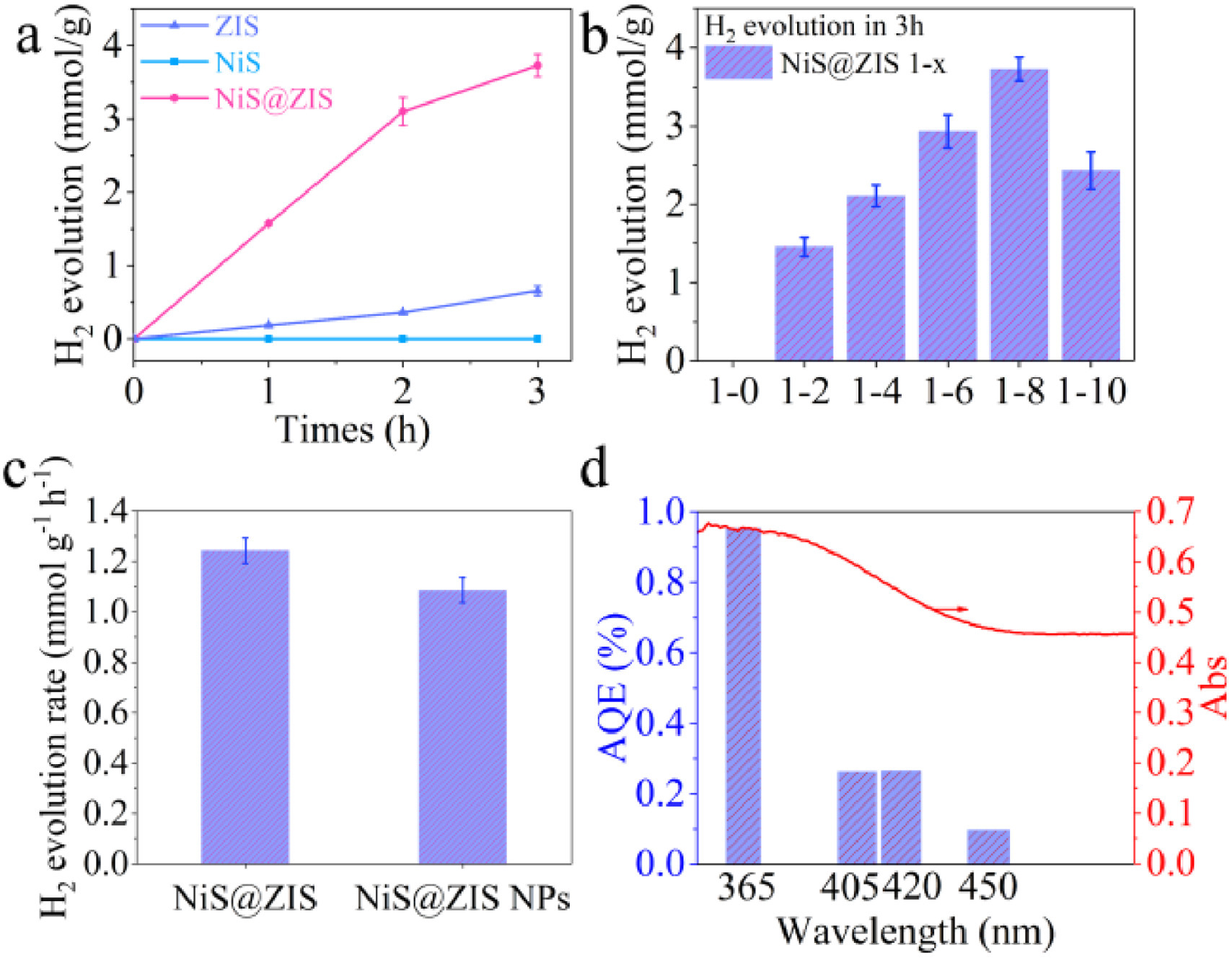
Fig. 2a shows the photocatalytic H2 production performance of different materials under visible light (λ > 400 nm), in the absence of co-catalyst and sacrificial agent. It is obvious that NiS is completely inactive to the photocatalytic reaction, because of the fast recombination of photogenerated charges. ZIS exhibits low photocatalytic activity, with a H2 production of 0.66 mmol/g for 3 h (0.22 mmol g-1 h-1). The performance is significantly improved after NiS coupling with ZIS, reaching up to 3.73 mmol/g under 3 h of light irradiation (1.24 mmol g-1 h-1), which is 5.6 times higher than that of ZIS. The optimal loading amount of ZIS on NiS surface was explored in Fig. 2b. The photocatalytic performance firstly increases and then decreases as a function of ZIS loading amount, and reaches the optimum when the mass ratio of NiS to ZIS is 1:8. Appropriate decoration of ZIS on NiS surface can extend the light absorption and promote the charge transfer from ZIS to NiS. However, when ZIS content exceeds the optimum, the superfluous ZIS clusters cause light shielding effect and in turn hinder the charge migration [41]. To demonstrate the superiority of hollow structure, solid NiS nanoparticles (NiS NPs) were synthesized (Fig. S12 in Supporting information) and ZIS nanosheets were grown on their surface, which was denoted as NiS@ZIS NPs (Fig. S13 in Supporting information). The photocatalytic performance of NiS@ZIS NPs was examined at the same condition. Showing a H2 production rate of 1.09 mmol g-1 h-1, the solid NiS@ZIS NPs possesses a lower photocatalytic activity than the hollow NiS@ZIS heterostructure (Fig. 2c). This can be explained by the absorption spectra of hollow NiS@ZIS and solid NiS@ZIS NPs in Fig. S14 (Supporting information). It is observed that the hollow heterostructure exhibits a stronger light absorption than the solid heterostructure, which is mainly due to multiple reflections inside the cavity of the hollow structure [27–31]. The apparent quantum efficiency (AQE) of NiS@ZIS under different monochromatic light irradiation, including 365, 405, 420 and 450 nm, was measured. It can be found from Fig. 2d that the hydrogen production efficiency is basically consistent with the light absorption capacity of NiS@ZIS composite, indicating that the water splitting is driven by the light excitation [42]. The stability of NiS@ZIS was checked by cyclic hydrogen evolution testing (Fig. S15 in Supporting information). It can be clearly seen that the hydrogen production performance declines with the cycles. This is due to the self-oxidation of the sulfide material when neither co-catalyst nor sacrificial agent is present in the reaction system. Therefore, the role of sacrificial agent on the photo-corrosion resistance of NiS@ZIS was verified, as displayed in Fig. S16 (Supporting information). When hole-scavenger (Na2S/Na2SO3) is present in the system, NiS@ZIS composite shows higher photocatalytic activity compared to ZIS (Fig. S16a), as well as satisfactory stability during the four tested cycles (Fig. S16b).

|
Download:
|
| Fig. 2. (a) Photocatalytic H2 evolution over ZIS, NiS and NiS@ZIS. (b) Photocatalytic H2 evolution performance of NiS@ZIS with different ZIS loading amount. (c) Photocatalytic H2 evolution rate of hollow NiS@ZIS and solid NiS@ZIS NPs. (d) Wavelength dependence of AQE and the light absorption spectra of NiS@ZIS photocatalyst. | |
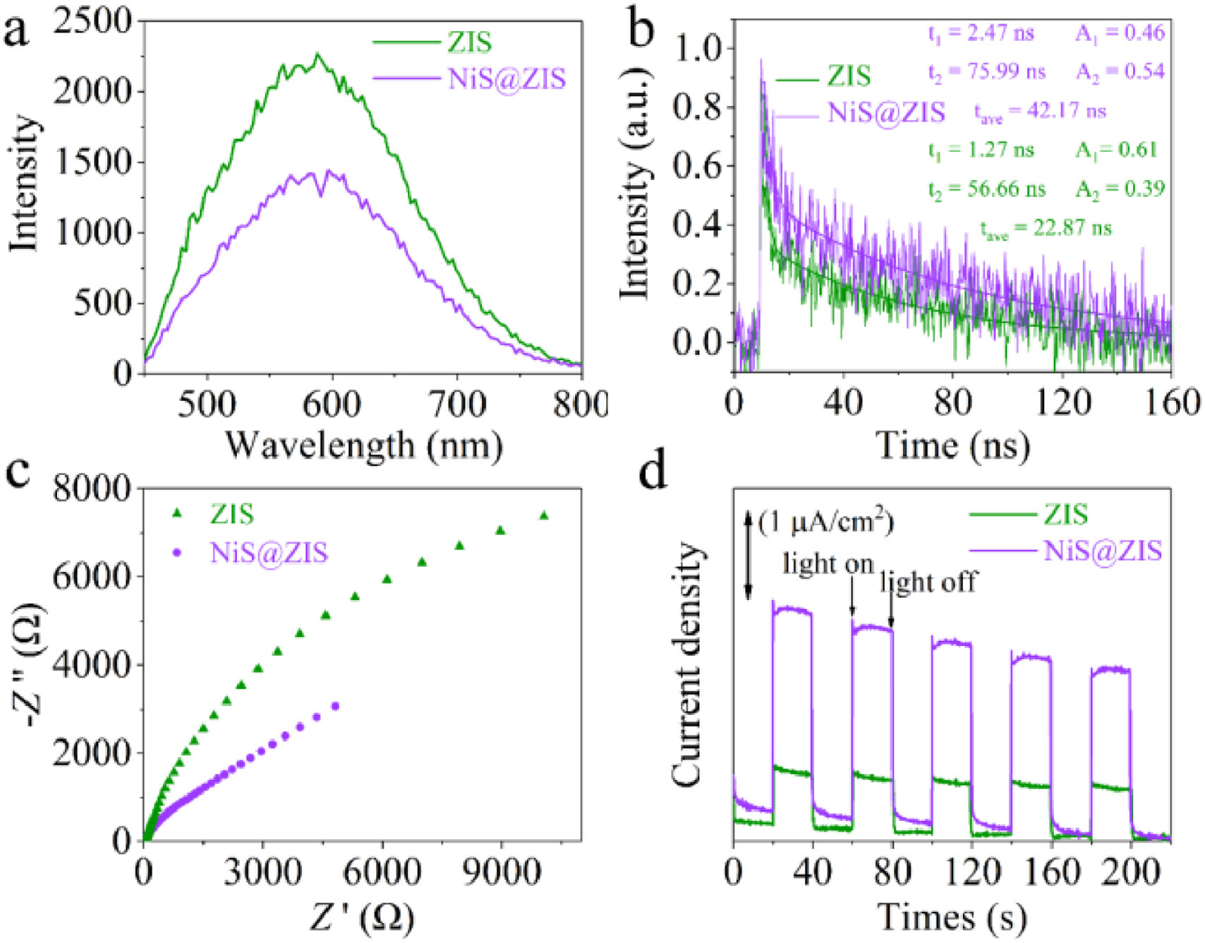
To understand the excellent performance of NiS@ZIS composite and confirm the charge transfer process, series of spectroscopic and photoelectrochemical (PEC) characterizations were performed. The steady-state photoluminescence (PL) spectra of NiS@ZIS displays obvious PL quenching compared with that of pure ZIS (Fig. 3a), indicating the charge transfer from ZIS to NiS. The PL lifetime of ZIS and NiS@ZIS was estimated by the time-resolved PL (TRPL) spectra (Fig. 3b). From the fitting results of the PL decay curve, NiS@ZIS exhibits a longer lifetime (42.17 ns) compared to ZIS (22.87 ns), indicating that the construction of heterostructure can effectively boost the separation of photogenerated electrons and holes, and thus prolong their lifetime. The results of PL and TRPL demonstrate the effective transfer of charge from ZIS to NiS. The electrochemical impedance spectra (EIS) of ZIS and NiS@ZIS were displayed in Fig. 3c. NiS@ZIS electrode manifests a smaller radius than ZIS electrode, suggesting a lower resistance and a more favorable charge transfer. In the transient photocurrent spectra (Fig. 3d), NiS@ZIS exhibits a larger photocurrent density than ZIS, indicating the improved photo-electric response in the heterostructure. All these results demonstrate that the hollow heterostructure effectively boost the separation and migration of carriers, inhibit the recombination of electrons-holes, extend the lifetime of carriers, thereby ensuring the high H2 production efficiency.

|
Download:
|
| Fig. 3. (a) Steady-state PL spectra, (b) time-resolved transient PL decay, (c) EIS spectra, and (d) transient photocurrent spectra of ZIS and NiS@ZIS. | |
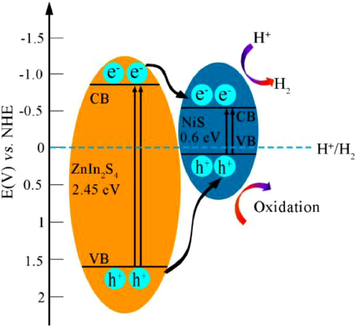
Based on the above analysis, the possible charge transfer mechanism is proposed (Fig. 4). The coupling of NiS with ZIS extend the light absorption to the full visible range. Under visible light irradiation, the hollow structure can absorb and utilize the light energy more efficiently by increasing the scattering and reflection of light. The electrons (e-) on the VB of ZIS and NiS are excited to their CB respectively, and then leave the same number of holes (h+) on their VB, forming electron-hole pairs. Due to the potential difference between NiS and ZIS, the electrons on CB and holes on VB of ZIS transfer to the CB and VB of NiS, respectively, boosting the separation and migration of photogenerated carriers. The larger surface area of the composite facilitates a sufficient contact between the catalyst with water. Meanwhile, plentiful active sites help the capture of more H+ for reduction reaction. Therefore, the combination of large surface area, multi light harvesting and effective charge separation is responsible for the superior photocatalytic activity of hollow NiS@ZIS heterostructure.

|
Download:
|
| Fig. 4. The separation and transfer process of photogenerated electrons (e-) and holes (h+) in the NiS@ZIS heterostructure. | |
In summary, hollow NiS@ZIS heterostructure photocatalyst was synthesized by growing ZIS nanosheets on NiS hollow spheres for efficient visible-light-driven hydrogen production from water splitting. Comparing with the pristine ZIS nanosheets, NiS@ZIS composites displayed higher light harvesting and surface area, which were benefit to the effective charge separation and migration in the heterostructure. Photocurrent, EIS, and TRPL results indicated that the coupling of two sulfides reduced the charge recombination and prolonged the charge lifetime. Based on the above factors, the NiS@ZIS composite exhibited a significant improvement in photocatalytic activity, with a hydrogen production rate of 1.24 mmol g-1 h-1 in the absence of any co-catalyst and sacrifice agent. This work will bring novel inspiration for the design of hollow structured photocatalysts for efficient charge separation.
Declaration of competing interestThe authors declare no conflict of interest.
AcknowledgmentThis work is supported by the Natural Science Foundation of Jiangsu Province (Youth Fund, Nos. BK20190640 and BK20190641).
Supplementary materialsSupplementary material associated with this article can be found, in the online version, at doi:10.1016/j.cclet.2021.07.011.
| [1] |
S. Wu, X. Shi, M. Zhu, Sustain. Energy Fuels 3 (2019) 1461-1467. DOI:10.1039/c9se00173e |
| [2] |
S. Fang, Y.H. Hu, Int. J. Energy Res. 43 (2019) 1082-1098. DOI:10.1002/er.4259 |
| [3] |
Y. Wang, F. He, L. Chen, et al., Chin. Chem. Lett. 31 (2020) 2668-2672. DOI:10.1016/j.cclet.2020.08.003 |
| [4] |
K. Chen, S. Deng, Y. Lu, et al., Chin. Chem. Lett. 32 (2021) 765-769. DOI:10.1016/j.cclet.2020.05.030 |
| [5] |
Y. Ji, J. Xie, Y. Yang, et al., Chin. Chem. Lett. 31 (2020) 855-858. DOI:10.1016/j.cclet.2019.06.021 |
| [6] |
Y. Xia, Q. Li, K. Lv, M. Li, Appl. Surf. Sci. 398 (2017) 81-88. DOI:10.1016/j.apsusc.2016.12.006 |
| [7] |
Y. Xiao, G. Tian, W. Li, et al., J. Am. Chem. Soc. 141 (2019) 2508-2515. DOI:10.1021/jacs.8b12428 |
| [8] |
Q. Wang, T. Hisatomi, Q. Jia, et al., Nat. Mater. 15 (2016) 611-615. DOI:10.1038/nmat4589 |
| [9] |
M. Liu, Y. Chen, J. Su, et al., Nat. Energy 1 (2016) 16151. DOI:10.1038/nenergy.2016.151 |
| [10] |
B. Lin, G. Yang, L. Wang, Angew. Chem. Int. Ed. 58 (2019) 4587-4591. DOI:10.1002/anie.201814360 |
| [11] |
R. Chen, Z.H. Yan, X.J. Kong, L.S. Long, L.S. Zheng, Angew. Chem. Int. Ed. 57 (2018) 16796-16800. DOI:10.1002/anie.201811211 |
| [12] |
H. Li, Y. Sun, Z.Y. Yuan, Y.P. Zhu, T.Y. Ma, Angew. Chem. Int. Ed. 57 (2018) 3222-3227. DOI:10.1002/anie.201712925 |
| [13] |
S. Wang, Y. Wang, S.L. Zhang, S.Q. Zang, X.W. Lou, Adv. Mater. 31 (2019) 1903404. DOI:10.1002/adma.201903404 |
| [14] |
X. Jiao, Z. Chen, X. Li, et al., J. Am. Chem. Soc. 139 (2017) 7586-7594. DOI:10.1021/jacs.7b02290 |
| [15] |
W. Chen, T.Y. Liu, T. Huang, X.H. Liu, X.J. Yang, Nanoscale 8 (2016) 3711-3719. DOI:10.1039/C5NR07695A |
| [16] |
S. Wang, B.Y. Guan, X. Wang, X.W.D. Lou, J. Am. Chem. Soc. 140 (2018) 15145-15148. DOI:10.1021/jacs.8b07721 |
| [17] |
M.Q. Yang, Y.J. Xu, W. Lu, et al., Nat. Commun. 8 (2017) 14224. DOI:10.1038/ncomms14224 |
| [18] |
S.T. Kochuveedu, Y.H. Jang, D.H. Kim, Chem. Soc. Rev. 42 (2013) 8467-8493. DOI:10.1039/c3cs60043b |
| [19] |
S. Sun, X. Yu, Q. Yang, Z. Yang, S. Liang, Nanoscale Adv. 1 (2019) 34-63. DOI:10.1039/c8na00196k |
| [20] |
G. Zhang, D. Chen, N. Li, et al., Angew. Chem. Int. Ed. 59 (2020) 8255-8261. DOI:10.1002/anie.202000503 |
| [21] |
S. Wang, B.Y. Guan, Y. Lu, X.W.D. Lou, J. Am. Chem. Soc. 139 (2017) 17305-17308. DOI:10.1021/jacs.7b10733 |
| [22] |
K. Iwashina, A. Iwase, Y.H. Ng, R. Amal, A. Kudo, J. Am. Chem. Soc. 137 (2015) 604-607. DOI:10.1021/ja511615s |
| [23] |
W. Chen, Y.X. Hua, Y. Wang, et al., J. Catal. 349 (2017) 8-18. DOI:10.1016/j.jcat.2017.01.005 |
| [24] |
A. Iwase, S. Yoshino, T. Takayama, et al., J. Am. Chem. Soc. 138 (2016) 10260-10264. DOI:10.1021/jacs.6b05304 |
| [25] |
H. Zhang, J. He, C. Zhai, M. Zhu, Chin. Chem. Lett. 30 (2019) 2338-2342. DOI:10.1016/j.cclet.2019.07.021 |
| [26] |
S. Zhang, X. Liu, C. Liu, et al., ACS Nano 12 (2018) 751-758. DOI:10.1021/acsnano.7b07974 |
| [27] |
X. Yao, X. Hu, Y. Cui, et al., Chin. Chem. Lett. 32 (2021) 750-754. DOI:10.1016/j.cclet.2020.05.013 |
| [28] |
B. Qiu, Q. Zhu, M. Du, et al., Angew. Chem. Int. Ed. 56 (2017) 2684-2688. DOI:10.1002/anie.201612551 |
| [29] |
D. Zheng, X.N. Cao, X. Wang, Angew. Chem. Int. Ed. 55 (2016) 11512-11516. DOI:10.1002/anie.201606102 |
| [30] |
A. Li, T. Wang, X. Chang, et al., Chem. Sci. 7 (2016) 890-895. DOI:10.1039/C5SC04163E |
| [31] |
S. Wang, B.Y. Guan, X.W.D. Lou, Energy Environ. Sci. 11 (2018) 306-310. DOI:10.1039/C7EE02934A |
| [32] |
J. Sun, J. Zhang, M. Zhang, et al., Nat. Commun. 3 (2012) 1139. DOI:10.1038/ncomms2152 |
| [33] |
T. Zhang, Q. Zhang, J. Ge, et al., J. Phys. Chem. C 113 (2009) 3168-3175. DOI:10.1021/jp810360a |
| [34] |
T. Zhu, Z. Wang, S. Ding, J.S. Chen, X.W.D. Lou, Res. Adv. 1 (2011) 397-400. DOI:10.1039/c1ra00240f |
| [35] |
J. Yang, X. Duan, W. Guo, et al., Nano Energy 5 (2014) 74-81. DOI:10.1016/j.nanoen.2014.02.006 |
| [36] |
Y. Wang, Q. Zhu, L. Tao, X. Su, J. Mater. Chem. 21 (2011) 9248-9254. DOI:10.1039/c1jm10271k |
| [37] |
G. Yang, D. Chen, H. Ding, et al., Appl. Catal. B: Environ. 219 (2017) 611-618. DOI:10.1016/j.apcatb.2017.08.016 |
| [38] |
J. Hou, C. Yang, H. Cheng, et al., Phys. Chem. Chem. Phys. 15 (2013) 15660-15668. DOI:10.1039/c3cp51857d |
| [39] |
G. Tian, Y. Chen, Z. Ren, et al., Chem. Asian J. 9 (2014) 1291-1297. DOI:10.1002/asia.201301646 |
| [40] |
L. Mao, X.Y. Cai, M.S. Zhu, Rare Met. 40 (2020) 1067-1076. |
| [41] |
S. Mao, J.W. Shi, G. Sun, et al., Appl. Catal. B: Environ. 282 (2021) 119550. DOI:10.1016/j.apcatb.2020.119550 |
| [42] |
H. Ou, L. Lin, Y. Zheng, et al., Adv. Mater. 29 (2017) 1700008. DOI:10.1002/adma.201700008 |