 2022, Vol. 33

b Department of Materials and Environmental Chemistry, Stockholm University, Stockholm 10691, Sweden
Nkongolo Tshamala Aristote is a master candidate at the College of Chemistry and Chemical Engineering, Central South University (China). He received B. Sc from the Polytechnics Faculty, Department of Metallurgical Engineering, University of Lubumbashi (D.R. Congo) in 2017. His research focuses on the construction of hard carbon as high initial coulombic efficiency and rate performance anode material for sodium-ion batteries.;
Kangyu Zou is a Ph.D. candidate at the College of Chemistry andChemical Engineering, Central South University. He received his B.Sc. and M.Sc. degrees from Northwest University (Xi’an, China) in 2015 and 2018, respectively. His research is focused on the construction of highperformance metal ion capacitors.;
Dr. Andi Di is currently a research fellow at Stockholm University, Stockholm, Sweden. She received master degree at Harbin Institute of Technology, and got Ph.D at University of Bath supervised by Prof. Karen Edler. Then she undertook postdoc work with Prof. Lennart Bergström at Stockholm University as a research fellow.;
Dr. Wentao Deng is currently a research fellow at Central South University, Changsha, China. She received master degree with the supervision of Prof. Xiaobo Ji at Central South University, and got Ph.D at University of Bath supervised by Dr. Petra Cameron. Then she undertook postdoc work with Prof. Laurie Peter at University of Bath before joining Central South University as a research fellow.;
Baowei Wang is a master candidate of College of Chemistry and Chemical Engineering, Central South University. He received his B.S. degree from China University of Mining and Technology in 2019. His research interests focus on the development of Nb-based materials for sodium-ion capacitors.;
Xinglan Deng is a master candidate of College of Chemistry and Chemical Engineering, Central SouthUniversity. She received her B.S. degreefrom Xiangtan University in 2019. Her research isfocused on the development of novel electrode materials for sodium ion capacitors.;
Hongshuai Hou is an Associate Professor at the College of Chemistry and Chemical Engineering, Central South University. He received his Ph.D. at Central South University in 2016. His current research interests are electrochemistry and key materials for electrochemical energy storage devices.;
Guoqiang Zou is an associate professor at the College of Chemistry and Chemical Engineering, Central South University. He received his Ph.D. from Central SouthUniversity in 2018. His current research interests are electrochemistry and key materials for electrochemical energy storage devices.;
Xiaobo Ji is a "Shenghua" Professor at Central South University and a Fellow of the Royal Society of Chemistry, specializing in the research and development of batteries and supercapacitor materials and their systems. He received his PhD in Electrochemistry in 2007 under the supervisionof Prof. Richard Compton at the University of Oxford and undertook postdoctoral work at MIT with Prof. Donald Sadoway..
Since many years ago, the fossil fuels have been used as the best energy sources in almost all the domains of energy. With rising concern about the consumption and exhaustion of the fossil fuels resources, and the serious environmental issues due to the use of the fossil fuels energy sources, great efforts have been made by the scientists to search and develop new sustainable and environmentally friendly energy sources. Besides, the demand for renewable energy storage systems with low cost, high efficiency, long lifespan, and adequate safety, has drawn the attention to energy sources such as rechargeable batteries, wind, solar, geothermal, water and tidal energy [1, 2]. Among all these energy sources, rechargeable batteries have been one of the most competitive candidates due to their benefits in the field of electrification of transportation and renewable energy integration [3].
Rechargeable lithium-ion batteries (LIBs) have been widely investigated and developed (1970-1980 s) as the most promised alternative for large scale energy storage systems. Due to thelimitationoflithium (Li) resources in the Earth's crust, the use of LIBs in the future for large-scale application in many fields ishindered [4]. As cheap and environmental friendly alternative to LIBs, sodium-ion batteries (SIBs), are particularly fascinating due to the Na Earth abundance compared to Li (23600 ppm vs. 20 ppm), and similar physicochemical characteristics between sodium and lithium. However, the development of materials for SIBs with enhanced performance, compared to those of LIBs still a challenge because of the large radius of Na+ (1.02 Å) than that of Li+ (0.76 Å) [5-7].
Many studies have been initiated to establish high performance electrode materials for SIBs, including metal oxides [9], metal selenite materials [8, 9], hard carbons (HC) [10-18], transition metal fluorides [19-21]and polyanionic (phosphates, silicates, sulfates) frameworks [21]. However, the sluggish rate of Na+ intercalation/deintercalation (sodiation/desodiation) process in these electrode materials hinders the achievement of high-performance electrode for SIBs (Figs. 1a and b) [22, 23]. Long cycle life and the first cycle irreversible capacity related to the irreversible consumption of Na+ ions during the sodiation/disodiation process and the formation of the solid electrolyte interface (SEI) on the electrode surface, the decomposition of the electrolyte, etc., are also hindering the high performance for the electrode materials for SIBs [24, 25].

|
Download:
|
| Fig. 1. (a) Illustration of the structure of a sodium ion battery. (b) Illustration of Na+ intercalation/deintercalation process of a working SIB. | |
To push SIBs to commercialization, the key point is to develop cheap and high-performance electrode materials including both anodes and cathodes materials. Previous studies on improving the performance of electrode materials are generally based on the investigation of the mechanisms of improving the initial coulombic efficiency (ICE) by controlling the SEI formation [26-29], the electrolyte decomposition and the consumption of Na+ ions [30].
Graphite has been considered as the standard anode material for LIBs, but it fails to be used in SIBs because of the unsuitable binary intercalation compound of Na-C system [31]. To overcome this, HC (carbon material that cannot be graphitized, or can be graphitized only at alow degree) has been developed as anode material for SIBs, owing to their low cost, the abundance and renewability of the precursor materials [32].
The cathode materials used in SIBs are mostly based on metallic materials (layered metal oxides, phosphates, fluorides, sulfides, sulfates, polyanion-type materials, etc.). Among all these cathode candidates, layered oxides (NaLMO2, LM = Ti, V, Cr, Mn, Fe, Co, Ni) offer many advantages due to their simple structures, high theoretical capacities in the 230-250 mAh/g range, and easy of synthesis [33].
Since the first cycle irreversible capacity and the rate performance are important for the long life SIBs, studying the mechanisms that influence the ICE and the battery performances for electrode materials to overcome the problem of battery low ICE and rate performance become important for the development and the commercialization of the SIBs. Therefore here we review several reported methods of improving the ICE and rate performance of SIBs associated with some electrodes materials as examples.
2. Methods to improve the ICE and rate performance for SIBsThis part will be subdivided into two parts: One is related to the methods improving the ICE and rate performance of anode materials of SIBs, and the other one related to the cathode materials.
2.1. Improving ICE and rate performance methods for SIBs regarding anode materials 2.1.1. Structural modificationThe intrinsic structure of the anode materials can be modified to enhance the rate performance, facilitating the sodiation/desodiation mechanism, reduce the irreversible consumption of Na+, thus, reduce the irreversible capacity. Several studies have been initiated to evaluate the influence of the material treatment on the ICE and rate performance.
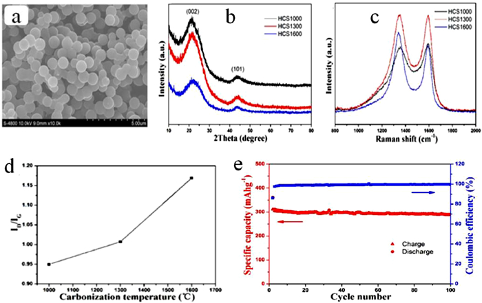
Controlling the carbonization process: Studying the effect carbonization process on the electrochemical performances of the electrode materialis mainly related to the HC materials making from organic precursors. HC have been considered as one of the most promising electrode materials for SIBs. However, the use of HC as anode material for SIBs is hindered by the low ICE. Controlling the carbonization process of the precursor is very important owing to fact that, increasing the carbonization temperature leads to the relatively high degree of graphitization and reduce the pores size of the HC material. The as-prepared HC material could exhibit a low specific surface area and the SEI films formation on the anode surface could decrease [34, 35]. Thus, the hard carbon material pyrolyzed at higher temperature obviously presents an optimum ICE. Contrarily, HCs pyrolyzed at a low temperature, usually exhibit a relatively low degree of graphitization including abundant defects and porosity [36]. The resulted HC material shows a large specific surface area, leading to the formation of large SEI films on the surface of the anode material and exhibiting a relatively low ICE. Therefore, controlling the carbonization temperature is considered as the elementary way to increase the ICE of HC as anode material, because it does not ask additional material or any other precursor pretreatment. Li et al. investigated on a HC from an abundant biomass of sucrose, and evaluated the influence of the carbonization temperature on micro-structure and electrochemical performance for the first time. The HC carbonized at 1600 ℃ showed the highest specific capacity of 220 mAh/g and excellent cycling performance with capacity retention of 93% after 100 cycles [37]. This excellent capacity might be explained by the structural characteristics (low defects, low pore concentration and low specific surface area) of HC that is found to contribute to the improvement of the electrochemical performances of the HC (Figs. 2a-c). From Fig. 2d, it can be seen how the ratio of the intensity of D-band peak and G-band peak (ID/IG) raises with the temperature, indicating an increase in the disorder degree while increasing the temperature [38]. When used as anode for a full cell SIB, the as prepared HC exhibited anICE efficiency of 76% as shown in Fig. 2e.

|
Download:
|
| Fig. 2. (a) The structure of the HC from SEM image. (b) XRD patterns. (c) Raman spectra. (d) The relation curve of ID/IG and carbonization temperature. (e) HCS-1600. Copied with the permission [37]. Copyright 2015, Royal Society of Chemistry. | |
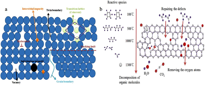
Defects and functional groups engineering: Defects are defined as the structural irregularities of the material. When the material shows more defects, its natural structure will be influenced by those defects (Figs. 3a and b). During the Na+ intercalation in the HC layers, there can be seen the formation of Na-Cx compounds that are responsible of enhancing battery performances [39, 40]. However, it is obvious that if the HC is well-arranged and contains fewer defects, the formation of Na-Cx is promoted and the sodium ion diffusion in layers is boosted. Normally, more defects in HC anode material can lead to the absorption of sodium ions and contribute to the improving of the capacity of the HC. In addition, HC contains oxygen owing to the fact that most of the organic precursors are oxygen containers. It is worthy to note that defects and functional groups show a high binding energy with sodium ions, and the irreversible capacities increases owing to the irreversible trapping of sodium ions by the defects and functional groups on one hand. On the other hand, increasing the carbonization temperature can effectively reduce the functional groups in the HC material and improve the ICE. Oxygen containing functional groups are considered as catalyzing the decomposition of electrolyte and forming more SEI layer [41]. Therefore engineering (removing or decreasing) the amount of such defects and functional groups in the HC materials is a common challenge for assuring a good Na+ ions intercalation/deintercalation process [42]. Several works have been initiated to engineer the defects and functional groups in the HC materials [43]. For example, research on deactivating the defects in the graphene using Al2O3nanoclusters for constructing long-life and high-rate SIBs [44]. The as prepared HC exhibited a higher ICE of about 70.2%, a high rate performance with the specific capacity of 155 mAh/g at 0.1 A/g, and the high capacity retention (82.9% after 500 cycles at 0.5 A/g). Figs. 4a-f present the structure comparison between porous graphene monolith (PGM) and PGM that defects have been covered by Al2O3nanoclusters, and the electrochemical characteristics are shown in Figs. 4g and h.

|
Download:
|
| Fig. 3. (a) Schematic illustration for various defects in crystals. (b) The in-situ engineering process of HC. | |

|
Download:
|
| Fig. 4. Comparison of structure and composition between porous graphene monolith (PGM) and PGM that defects have been covered by Al2O3 nanoclusters. (a) SEM images together with the elemental maps of carbon, oxygen, and aluminum of PGM-T. (b) Al2O3/PGM-5. (c) XRD patterns of Al2O3/PGM-2, Al2O3/PGM-5, Al2O3/PGM-12 and PGM-T. (d) Raman spectra of Al2O3/PGM-5 and PGM-T. High-resolution XPS: (e) O 1 s spectra. (f) Al 2p spectra of Al2O3/ PGM-5 and PGM-T. (g) Rate performance for Al2O3-nanoclusters/PGF electrodes at current densities ranging from 0.1 A/g to 5 A/g. (h) Cycling performance of PGM-T and Al2O3-nanoclusters electrodes at 0.5 A/g. Reproducedwith permission [44]. Copyright 2018, Wiley Online Library. | |
Wang et al. have prepared a kelp-based HC materialwhich exhibited a relatively high ICE (more than 61.2%) when largely decreased the oxygen functional groups below 16.62%, owing to the decreasing of irreversibly consumed Na+ ion in the anode material. Another study have been done on the reduction of the oxygen from an apricot shell based HC using H2, and was found that the ICE increased from 69% to 79% [45]. Sun et al. reported a new in-situ engineering approach to deliberately tune the residual oxygen atoms/defects of hard carbon, by controlling the atmosphere of the carbonization process (pyrolysis synthesis) [46]. Theas-prepared anode material exhibited an ICE of over than 85%.
Surface engineering: The purpose of the surface engineering in the field of electrode materials is to reduce the specificsurface area (eliminating the material pores), to inhibit (or at least to reduce) the formation of the SEI on the anode surface. For example, as it can be seen from Figs. 5a and b, the difference between the specific surface area of an untreated sucrose-derived carbonm materialand the CO2 treated sucrose-derived carbon material (1410.3 m2/g and 58.7 m2/g, respectively) [47]. Specific surface area of the anode material is among the practical factorsthat reduce the ICE, due to its impact on the irreversible capacity.

|
Download:
|
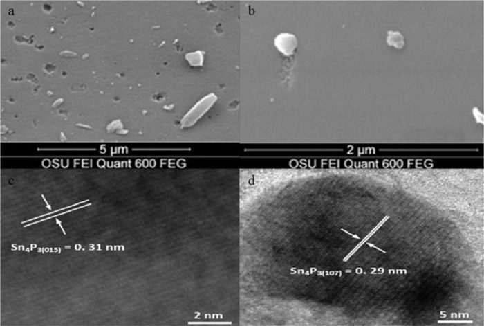
| Fig. 5. (a) SEM images showing the comparison between surface morphology of sucrose-derived carbon pyrolysed at 1000 ℃ and activated under CO2 at 900 ℃ for 10 h. Mesopores (2–50 nm) and micropores (less than 2 nm) are not observable at such low magnification and (b) pyrolysed at 1000 ℃, unactivated. (c, d) HRTE images display the lattice planes of these encapsulated Sn4P3 nanoparticles. Reproduced with permission [47, 51]. Copyright 2014, Elsevier, Copyright 2015, Royal Society of Chemistry. | |
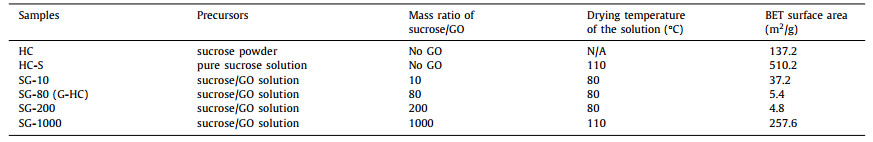
HC materials, as the promised anode materials for SIBs, comprise of a mass of irregular graphite microcrystals and structural micropores due to insufficient or low degree of graphitization. Therefore HC generally show large specific surface area of several thousand square meter per gram, and favorable for the formation of the SEI on the anode surface.Previous studies focused on establishing anode materials with low specific surface area (Table 1), and evaluatedthe relationship between the specific surface area and the ICE of the full cell battery. For example, Hong et al. prepared a porous pomelo peels derived HC, by the simple pyrolysis of H3PO4-treated biomass at 700 ℃ under N2 atmosphere [48]. The as-obtained HC showed a large specific surface area of 1272 m2/g, and exhibited an ICE of 27%. Luo et al. prepared a graphene oxide doped sucrose as the precursor for HC to reduce the specific surface area of the HC (named as G-HC), and study the effect on the ICE [49]. The as prepared HC showed a small specific area of about 5.4 m2/g, and exhibited an ICE of 83% in the first cycle of discharge/charge process. The G-HC also showed a good rate performance, the high capacity revered when the current density returned to 20 mA/g after cycled at higher rates, as shown in Fig. 6a.
|
|
Table 1 Sucrose powder, pure sucrose solution and sucrose/GO suspension/solution. Reproduced with permission [49]. Copyright 2017, Roysl Society of Chemistry. |

|
Download:
|
| Fig. 6. (a) Rate performance of HC (blue) and G-HC (black) tested from 20 mA/g to 1000 mA/g and then at 20 mA/g for long-term cycling in the potential range of 0.01−2 V. (b) Rate performance of Sn4P3/C at different rates (increased from 0.2 C to 3 C). (c) The cycling performance of hard–soft carbon composites at 150 mA/g. (d) The rate performance of hard–soft carbon composites from 30 mA/g to 1200 mA/g. Copied with permission [49, 51, 52]. Copyright 2015, ACS Publications. Copyright 2015, Royal Society of Chemistry. Copyright 2019, Wiley Online Library. | |
Surface coating has been used in the aim of limiting undesirable side reactions.Carbon has been the most used material for surface coating, owing to its large electrochemical window and fine chemical stability in common electrolyte systems.For example, Liu et al. prepared a SnO2 surface coated with carbon by hydrothermal process, followed by phosphorization as high performance anode material for SIBs. The as-prepared anode material named Yolk-shell Sn4P3/C nanospheres, showed a uniformly and fully encapsulated Sn nanoparticles and well defined void space between the inner yolk and outer shell. The observed lattice spacing were of about 0.31 nm and 0.29 nm corresponding to the (015) and the (107) plane distances of rhombehedral Sn4P3 respectively (Figs. 5c and d), that could explain the outstanding rate performance with reversible capabilities of 720, 651, 581, 505 and 421 mAh/g at 0.2 C, 0.4 C, 0.8 C, 1.5 C and 3 C, respectively for the Sn4P3/C anode material (Fig. 6b) [50, 51]. Xie et al. also prepared a filter paper (FP)-mesophase pitch (MP) composite of FP/MP ratio of 5:2 weight, to synthesize an anode material able to show the characteristics of both hard and soft carbon (the shape of carbon that can easily be graphitized) [52]. The as synthesized composite material presented better electrochemical performance than that of the pure hard and soft carbon, with a high ICE of 80% compared to an ICE of 37% only of the pure hard carbon (Fig. 6c). The composite material showed complementarity between the hard and soft carbon, such as the soft carbon in the composite successfully occupies the open pores of the hard carbon, reducing the specific surface area and providing a certain amount of active Na+ storage sites. And the large interlayer spacing of hard carbon is beneficial for the intercalation of Na+. The specific capacities of all the composites recovered to the value at 30 mA/g after cycling at higher current rates, indicating that the composite carbon anodes have good rate performances and stability within a wide range of current densities (Fig. 6d).
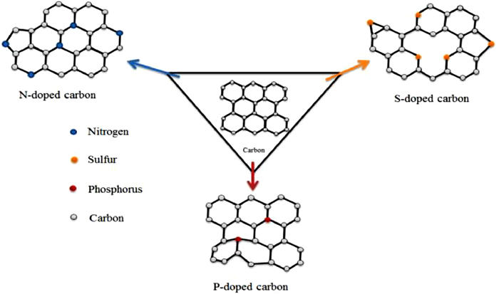
2.1.2. Effects of heteroatom dopingHeteroatom doping is defined as the process that consists on introducing some atoms (in low proportion) into another, considered as the main material (Fig. 7), for modifying some specific properties of the main material, according to the need. In the field of anode material preparation, atoms such as nitrogen, boron, sulfur, phosphorus, iodine can be introduced into the hard carbon material forfulfilling the potential of the anode material and ameliorate the characteristics of carbon material, such as surface structure, electronic conductivity, interlayer spacing [53, 54]. This section will be developed with the studies of the heteroatoms (N, S, P and I) doped anode materials for SIBs.

|
Download:
|
| Fig. 7. Scheme illustrating the heteroatom-doping of N, S and P in the carbon material. | |
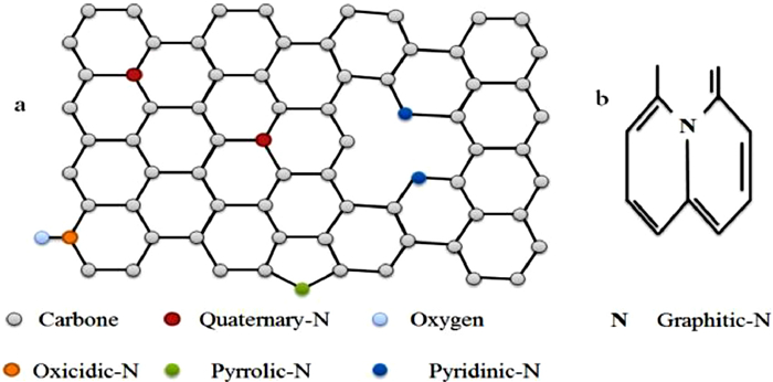
Nitrogen doping: Many studies have been initiated on the effect of nitrogen doping on the electrochemical performances of the anode materials. N-doping can significantly improve the electronic conductivity and offer more sodium active storage sites for HC, and improve the electrochemical performance of the HC [55]. Nitrogen doped HC materials can be prepared by pyrolyzing the N-containing precursors and N-rich compounds and by pyrolyzing the precursor under the N2 atmosphere. It is distinguished different types of nitrogen doped materials according to the position of N inside the material. The observed cases in the field of electrode materials are the pyridinic-N, pyrrolic-N, graphitic-N, quaternary-N, etc. (Figs. 8a and b).When presents in the HC material, the pyridinic-N is responsible for bothenhancingthe reversible capacity by providing more active sites and favoring the decomposition of electrolyte and traps Na+ ions, owing to its pair of lone electrons [56]. High-temperature pyrolyzing of the precursor leads to the growth of the graphitization degree, and the decrease of the defects in the resulted HC material. However, high-temperature pyrolysis decreases the amount of the pyridinic-N. This consideration makes thepyrolysis process to be very conscientious for the design of advanced HCs. Zhu et al. synthesized a nitrogen-doped carbon nanofibers (N-CNFs) derived from polyacrylonitrile, by a combination of electrospinning and thermal treatment processes [57]. The N-CNFs carbonized at 800 ℃ showed excellent cycling and rate performance, although the ICE was about 64%. The low ICE could be explained by the irreversible trapping of some Na+ ions in the defects and functional groups of the as obtained HC in the first cycle. Li et al. synthesized a nitrogen-doped HC on nickel foam (NC/NF) with numerous active sites, an expanded interlayer distance of 0.49 nm, and highly ordered pseudo-graphic structure, by a melamine-assisted hydrothermal pretreatment and subsequent pyrolysis procedure [58]. The NC/NF contained high configurations of pyrrolic-N and pyridinic-N. When served as anodes for SIBs, NC/NF exhibited high rate performance with the capability of 128.5 mAh/g at 10 A/g, and excellent cycling stability with 225.4 mAh/g maintained after 1000 cycles at current density of 5 A/g. To understand the effect of nitrogen doping in hard carbon as anode for SIBs and see the size effect along with nitrogen doping, Lim et al. designed a nitrogen-doped MoS2/Silicon oxycarbide nanoscale heterostructure as high performance anode for SIBs [59]. The as-designed nitrogen doping in a two-dimensional MoS2 structure was led to the enlargement of the interlayer spacing and enhancement of the electronic conductivity and mechanical stability, which allows the facile, highly reversible insertion and extraction of sodium ions upon cycling.

|
Download:
|
| Fig. 8. (a) Illustration of different types of N-doping. Quaternary-N, oxicidic-N, pyrolic-N, pyridinic-N and oxygen doped carbon material. (b) Graphitic-N. | |
Regarding the above studies, nitrogen doping is found to be one of the successful ways to enhance the electrochemical performance of HCs.
Phosphorus doping: Phosphorus can also be doped into HC. The difference between phosphorus and nitrogen doping is, nitrogen can occupy the lattice sites of the HC materialdue to thesimilar atomic radius as C atom, while phosphorus atoms difficultly insert the lattice site due tothe relatively atomic radiusof phosphorusthat is larger than nitrogen atoms [60, 61], but generally onlybond with C and O. However, phosphorus doping can effectively expand the interlayer spacing and increase the reversible capacity. It was reported that the presence of P=O and P−C bonds in graphitic layers when doped with phosphorus inhences the the Na+ insertion [62]. The most commonly way to realize P-doping ispretreating the precursor using phosphoric acid. Previous studies have confirmed that phosphorus is mainly present in the form of POx in the HCs. Moreover, phosphorus doped HC materials exhibit a remarkably low ICE but an outstanding rate performance.This could be explained by the presence of phosphorus that facilitates more Na+ ion intercalation in the HCby increasing the interlayer spacing of the HC structure, but the deintercalation process becomes difficult during the first cycle of discharge/charge process [63].
Sulfur doping: Sulfur-doping also plays an important role in the mechanism of Na+ transfer, owing to the fact that sulfur has an ability to reversibly react with Na+, and is considered as a sodium electrochemically active element, exhibiting a reversible peaks in CV and charge/discharge curve. When doped in HC material, same as N-doping, S is also responsibleof enhancing the reversible capacity of the HC materials, butis accompanied byhigh voltage, thathas a negative effect on the energy density of the battery. In addition, S-doping can effectively enlarge the interlayer spacing of the HC material due to the large radius of sulfur atom, which facilitates the intercalation/deintercalation process of Na+. Mixing elemental sulfur or S-containing compounds with precursor before carbonization seems to be the common ways for achieving the S-doping [64, 65]. Zhao et al. obtained a three dimensional (3D) framework of carbon nanosheets heavily-doped with sulphur (S–CNS) from plant biomass using a facile thermal method [66]. The S–CNS exhibited an ultrahigh reversible capacity of 605 mAh/g at 50 mA/g and a high rate performance with capacity of 133 mAh/g at 10 A/g. Feng et al. also prepared a type of sulfur-doped carbon (SC) by pyrolyzing the freeze-dried gel of agarose and sulfur powder as anode material for SIBs [67]. It was found that most of the sulfur atoms were doped between (002), andthe as prepared SC material exhibited an initial discharge capacity of more than 420 mAh/g at 100 mA/g. When cycled at various current densities from 0.1, 0.2, 0.3, 0.5, 1.0, 2.0 A/g to 3.0 A/g, the reversible specific capacitiesare 331, 293, 273, 245, 207, 152 and 110 mAh/g, respectively.
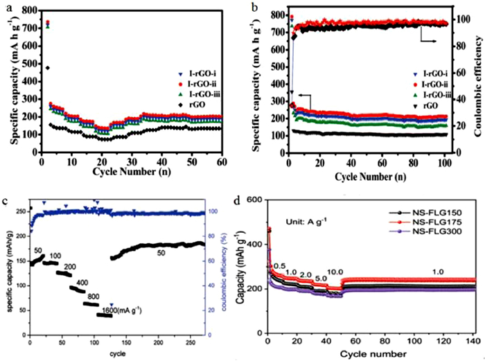
Iodine doping: Iodine doping has not been much inveqstigated, thus the effect of I-doping is not well understood yet. However, Li et al. reported an iodine-doped reduced graphene oxide as anode for sodium ion batteries, and named as I-rGO. Graphene oxide was firstly synthesized by a modified Hummers method, and then mixed with iodine in ethanol. The as prepared anode material was found to enlarge the d-spacing of the rGO, and the defects was constructed leading to more Na+ ion storage, fast electron transport and Na+ ion diffusion, and being responsible of better rate performance with capacities of 275, 201, 185 and 148 mAh/g at current densities of 50, 100, 200 and 500 mA/g, respectively and an ICE close to 90% (Figs. 9a and b) [68]. Based on these results, it can be concluded that iodine doping can enlarge the interlayer spacing of the material, provide the defects, and facilitate the Na+ ion transport and storage. However, the iodine doping has to be more developed to more understand its effect on the electrochemical performances of the anode materials.

|
Download:
|
| Fig. 9. (a) Rate performance of the I-rGO anode material. (b) Cycling performance and coulombic efficiency of the I-rGO. (c) Rate performance of Na0.25TiO2. (d) Rate performance of NS-FLG. Reproduced with permission [68, 70, 71]. Copyright 2017, Royal Society of Chemistry. Copyright 2015, Royal Society of Chemistry. Copyright 2017, Royal Society of Chemistry. | |
Molten salt can be defined as a salt which is solid at standard temperature and pressure but enters the liquid phase due to elevated temperature. Molten salt synthesis is based on a modification of the powder metallurgical method. Salt with a low melting point is added to the reactants and heated above the melting point of the salt, the molten salt acting as the solvent.Molten salts is used as additives to enhance the rates of solid state reactions for a long time. The amount of salt is small, typically a few percent of the total weight. In contrast, in molten salt synthesis, a large amount of salt is used as the solvent to control powder characteristics (size, shape, etc.) [69]. Molten salt synthesis methods can be sonsidered as a method of improving ICE and rate performance owing to its principle of associating several components, to enhence electrochemical properties of the resultant material (kind of doping). For exemple, Li et al. investigayted on a molten salt electrochemical synthesis of sodium titanates as high performance anode materials for sodium ion batteries [70]. The obtained Na0.25TiO2 anode materials showed an ICE of more that 80% and ahigh rate performance with a specific capacity of 185 mAh/g at 50 mA/g (Fig. 9c). Liu et al. Also prepared a SIBs anode enabled by a low temperature molten salt approach using nitrogen and sulfur in a few-layer graphene (NS-FLG) by annealing graphen oxide in KSCN moltensalt at 175 ℃. The as prepared NS-FLG exhibited a high rate performance with the capacity of 205 mAh/g at 10 A/g (Fig. 9d) [71].
2.2. Improving ICE and rate performance methods of the cathode materials for SIBsRecently, many studies have been carried out to develop high-performance cathode materials for SIBs (such as layered transition metal oxides, transition metal fluorides, phosphates). It was reported that these materials exhibit low specific capacity for energy storage, attributed to weak structural integration and large variations in volume [72-74]. In this section, some methods to overcome the problem of low ICE and rate performance of cathode materials for SIBs are discussed, based on previous studies.
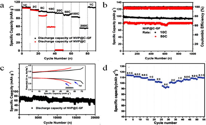
2.2.1. Material coatingCoating is a process of covering the surface of an object using another material. Generally coating may be decorative, functional, or both. Functional coatings are used to change the surface properties of the original material, such as adhesion, wettability, corrosion resistance or wear resistance. Concerning the field of cathode materials, surface coating has been widely investigated to enhance the life, rate performance and achieve an improved cathode performancefor SIBs [75, 76]. Zhong et al. prepared a carbon-coated Na3V2(PO4)3 anchored on freestanding graphite foam (denoted as NVP@C-GF) as a cathode material for SIBs. The as-preparedNVP@C-GF exhibited superior sodium-ion storage performance; including rate performance with a specific capacity of 56 mAh/g at 200 C and long cycle life of 54 mAh/g at 100 C after 20000 cycles (Figs. 10a-c) [77]. Li et al. synthesized a 3D hierarchical Na3V2(PO4)3 particles by a facile hydrothermal method, constructed by carbon-coated 2DNa3V2(PO4)3nanowalls. This composite material exhibited superior rate performance as shown on the Fig. 10d [78].

|
Download:
|
| Fig. 10. (a) The rate performances of NVP@C-GF and NVP@C cycled at different current rate from 1 C to 200 C. (b) Long-term capability test for NVP@C-GF at a current rate of 10 C and 50 C for 1000 cycles after activated for 5 times at a current rate of 1 mA/g. (c) Long-term capability test for NVP@C-GF at a current rate of 100 C for 20000 cycles after activated for 5 times at a current rate of 1 C. Inset: voltage profiles of NVP@C-GF for the 1st and 20000th cycle at a voltage range from 2.7 V to 3.8 V. (d) The rate performances of H-NVP. Copied with the permission [77, 78]. Copyright 2016, ACS Publications. Copyright 2016, Wiley Online Library. | |
Sol–gel process is defined as a method to produce solid materials from small molecules. It is generally used for the fabrication of metal oxides, especially the oxides of silicon (Si) and titanium (Ti). The process involves conversion of monomers into a colloidal solution (sol) that acts as the precursor for an integrated network of either discrete particles or network polymers. Here there are hydroxylation-condensation reactions that provide an oxide material from a precursor solution. Therefore, it is possible to chemically control the morphology and the structure of the material. The major advantages of this method are a lower processing temperature and better atomic distribution in multi-component materials [79]. Some studies have been conducted following the sol-gel synthesis method to construct high performance cathode materials for SIBs [80]. Some studies have been conducted on the effect of the alloy cathode materials on the electrochemical performances of the SIBs. Ma et al. synthesized a Ti substituted P2-phase Na0.8(Li0.33Mn0.67-xTix)O2 cathodes by a simple sol-gel method. Used as cathode for SIBs, the as synthesized material exhibited a ICE of 87.8% and the rate performance with the specific capacity of 85 mAh/g at 500 mA/g. These best electrochemical results was attributed to the Ti substitution that effectively enhance the electrochemical properties of P2-type Na0.8(Li0.33Mn0.67-xTix)O2 cathodes [81]. Also Hou et al. synthesized a Na0.67Ni0.23Mg0.1Mn0.67O2 by sol-gel method as cathode material for SIBs. After it has been used for full cell SIBs, the as synthesiuzed catode delivered an initial reversible capacity of 105 mAh/g at a charge/discharge current density of 48 mA/g. The authors concluded that the improved high rate performance of the as this cathode material was attributed to the increased lattice parameters and d-spacing of the Na+ layer due to the Mg-doping in Na0.67Ni0.23Mg0.1Mn0.67O2. Sol gel synthesis method is a promising way to construct high rate performance cathode materials for sodium-ion batteries [82].
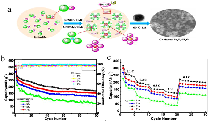
2.2.3. DopingApart from nanoscale design and surface engineering, heteroatom doping is one of the effective ways to enhance the intrinsic transfer characteristics of sodium ions and electrons to accelerate reaction kinetics and thereby achieve high performance [75]. As it was discussed above from the section of heteroatom doping concerning the anode material, the aim of doping in the cathode materials isthe same, to bring new atoms inside the material and improve its electrochemical properties.The heteroatomic doping can be achieved by using metalic or non metallic materials. Researchers have initiated studies on theimpact of the heteroatom doping on the ICE and rate performance of the cathode materials for SIBs. For example, Singh et al. synthesized Na2/3[Fe1/2Mn1/2]O2 by conventional solid state synthesis. NaH3 was mixed with Na2/3[Fe1/2Mn1/2]O2, as source of extra Na+ during the first cycle.The results of the electrochemical tests revealed that the as synthesized cathode material improved the irreversible capacity loss upon about 50% (from 59 mAh/g to 27 mAh/g) [83]. Liu et al. also prepared a Fe(2-x)CrxF5·H2O (x = 0, 0.03, 0.05, 0.07), Cr-doped Fe2F5·H2O, as cathode materials for SIBs (Fig. 11a) [84]. Electrochemical tests revealed that the Cr-doped samples exhibited relatively higher discharge capacity, which might be explained by the increase of the structure stability and the electronic conductivity due to Cr doping, compared to the bare Fe2F5·H2O. The initial discharge capacities when x = 0.03, 0.05, 0.07 are 316, 357 and 338 mAh/g respectively, and the rate performance of these materials displayed in the Figs. 11b and c. Deng et al. developed a green route strategy to fabricate a carbon-coated Na2FePO4F cathode for SIBs, using vitamin C as the carbon source and environment-friendly water-based polyacrylic latex as the binder [85]. It was found that the Na2FePO4F phase in the as-derived Na2FePO4F/C electrode shows a high reversible capacity of 117 mAh/g at a cycling rate of 0.1 C, and an excellent rate performance was achieved while retaining the outstanding cycling stability (about 85% capacity retention after 1000 cycles at a rate of 4 C.

|
Download:
|
| Fig. 11. (a) Illustration of the synthetic process of Cr-doped Fe2F5.H2O cathode materials. (b) Cycling performances of Fe(2-x)CrxF5·H2O nanocomposites (x = 0, 0.03, 0.05, 0.07) electrodes at 0.1 C rate within the voltage range of 1.0 V to 4.0 V. (c) Rate capabilities of Fe(2-x)CrxF5·H2O (x = 0, 0.03, 0.05, 0.07) cells. Reproduced with the permission [84]. Copyright 2018, Elsevier. | |
Based on these reported study, it can be concluded that Na-doping is an effective way to enhance the ICE and rate performance of SIBs owing to the fact that Na provide extra Na+ ions inside the cathode material during the charge/discharge process, while Cr-doping is favorable to increase the stability of the structure and the electronic conductivity, thus increase the rate performance.
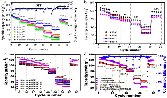
2.2.4. Co-precipitation methodCo-precipitation is a method to precipitate simultaneously two or more soluble raw materials to form a gathering which settled or carried down by the help of precipitant agent due to the reaction between the materials and the precipitant. In most cases the co-precipitation method uses hydroxide (OH) or carbonate (CO3) co-precipitation, with NaOH as hydroxide source and Na2CO3 as the carbonate source, for the simple reason that it provides cathode materials precursors of multiple compounds with high level homogeneity at the atomic level and spherical morphology particles with a narrow particle distribution, high tap density, and good fluidity [86]. It is in fact a kind of heteroatom doping, since it mixes two or more compounds. Zhang et al. synthesized a P2-Na0.56[Ni0.1Co0.1Mn0.8]O2(SPP) nanowires through a sodium peroxide pouring. The as synthesized cathode material showed an extremely high ICE of more than 90%, and excellent rate performance with a specific capacity of 80 mAh/g at a high current density of 2400 mA/g as shown in the Fig. 12a [87]. Zuo et al. also prepared an Na2MnFe(CN)6 and reported the effect of co-precipitation pH on the synthesizedcathode material. At the pH value of 3.0, the Na2MnFe(CN)6 cathode material exhibited high rate performance with a specific capacity of about 126 mAh/g at 0.1 C, while the specific capacity decreased to about 100 mAh/g at the pH value of 9.0 (Fig. 12b) [88]. Wang et al. synthesized a NaFeFe(CN)6 (NFF) via a citrate assisted co-precipitation route, and investigated on the effect oflow-level Ni doping in NFF as cathode materials in 1 mol/LNaNO3 electrolyte.The obtained NFF-N0.23 cathode material exhibited best rate performance with the specific capacities of 110.2, 105.9, 100.3, 94.5, 80.3 and 55.5 mAh/g at a current density of 100, 200, 300, 500, 1000 and 2000 mA/g, respectively and the ICE more than 75% (Figs. 12c and d) [89]. From all these results, the co-precipitation method can be considered as a promized method to synthesize high ICE and rate performance cathode materials for SIBs.

|
Download:
|
| Fig. 12. (a) The rate performance of SPP. (b) Rate performance of of PBM-X electrodes. (c, d) Rate performance and coulombic efficiency of the NFF and NFF-N. Reproced with permission [87-89]. Copyright 2018, Chemistry Europe. Copyright 2019, Elsevier. Copyright 2018, Elsevier. | |
Material Coating, Alloying structured materials, doping materials and co-precipitation are seems to be the promising ways for improving the ICE and rate performance of cathode materials for SIBs.
The ICE is mainly affected by the formation of the solid electrolyte interface (SEI) on the electrode surfaces, the irreversible consumption of sodium ions during the cycle of charge/discharge process, side reactions, etc. [90]. These phenomena lead to the irregularity of the Na+ mobility inside the electrode material (intercalation-deintercalation, insertion-deinsertion, sodiation-desodiation, etc.) [91]. However, it is worthy to note that the ICE could be influenced by more other factors that are not understood yet.
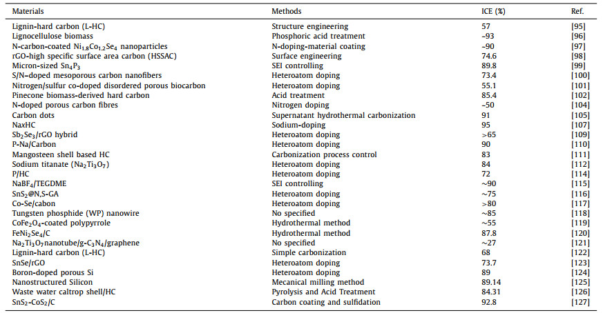
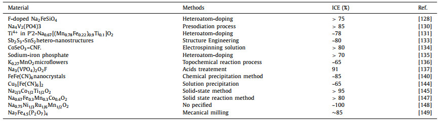
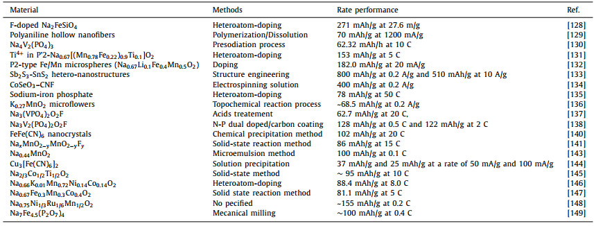
The rateperformance is mainly influenced by the structure of the electrode materials that generally affect the rateof the Na+ ions mobility in the material [92-94]. Improving the ICE and battery performance is based on the study and the understanding of the mechanisms that mainly negatively influence them (SEI formation on the electrode surface, Na+ irreversible consumption etc.).Herein, we have summarized some methods of improving the ICE and rate performance for SIBs. However, some of them are not given above, but can be found as examples in Table 2-5 [95-149]. Tables 2 and 3 are related to the anode materials and illustratesome reported materials and methodes of improving the ICE and ratre performance respectively, and the Tables 4 and 5 are related to the cathode materials and illustrate some materials and methodes of improving the ICE and rae performance respectively.
|
|
Table 2 Classification of methods for the reported ICEof the anode materials for SIBs. |
|
|
Table 3 Classification of methods for the reported rate performances of the anode materials for SIBs. |

|
|
Table 4 Classification of methods for the reported ICE of the cathode materials for SIBs. |
|
|
Table 5 Classification of methods for the reported rate performances of the cathode materials for SIBs. |
To develop SIBs with energy density for practical applications, anode and cathode materials with high ICE and rate performance are of great importance.
Great efforts have been made to understand low ICE and rate performance and here we have summarized the main and well known reasons for low ICE and rate performance: (1) The irreversible consumption of Na+ ion during the sodiation/desodiation. The amount of the Na+ inserted in the electrode material during the insertion process is much higher than that delivered back by the electrode material during the desodiation process, so that it accuses an insufficient Na+ amount for sustainable cycle. (2) Irreversible consumption of the Na+ ion caused by the formation of the SEI on the surface of the electrode material. (3) The irreversible consumption of the Na+ due to the decomposition of the electrolyte (side reactions).
After studying and understanding the reasons that lead to the poor ICE and battery performances, researchers have developed different ways to overcome these problems. Here we have selected and summarized recent advances that related to the improvement of the ICE and the rate performance. These methods are mainly based on: (1) Controlling and reduce the formation of the SEI, by the preparation of the electrode material with a low surface area. (2) Regulating the amount of defects and oxygen containing functional groups in the electrode material, for the anode material (mainly HC anode materials). (3) Controlling the structure of the electrode materials by heteroatom doping. (4) Adding different materials to reduce the electrolyte decomposition during the battery working. (5) Preparing different types of cathode materials such as transition metal oxides, metal sulfides, fluorides, phosphates, sulfates, to evaluate the charge transfer capabilities. (6) Using the presodiation materials as electrode, or Na doping the electrode material to bring extra Na+, and compensate the irreversible consumption of Na+. (7) The choice of the method and the synthesis parameters of the preparation of precursors and the preparation of the electrode material.
Nevertheless, challenges on enhancing the ICE and rate performance for the SIBs still remain. Therefore solutions such as searching for strategies to eliminate or extremely reduce the irreversible consumption of Na+, to achieve an ICE of 100% (or close to 100%), finding a standard synthesis method to prepare an electrode material with a favorite structure to achieve a high rate performance, optimizing the electrode preparation conditions to reduce side reactions are necessary.
Declaration of competing interestThe authors declare no conflict of interest.
AcknowledgmentThis work was financially supported by National Key Research and Development Program of China (No. 2019YFC1907805), National Natural Science Foundation of China (No. 52004338), Hunan Provincial Natural Science Foundation of China (No. 2020JJ5696), and Guangdong Provincial Department of Natural Resources (No. 2020-011).
| [1] |
K. Feng, M. Li, W. Liu, et al., Nano Micro Small 14 (2018) 1702737. |
| [2] |
Y. Lu, L. Yu, X.W. Luo, Chem. 4 (2018) 972-996. DOI:10.1016/j.chempr.2018.01.003 |
| [3] |
W. Wang, B. Schwenzer, J. Xiao, et al., Nano Lett. 12 (2012) 3783-3787. DOI:10.1021/nl3016957 |
| [4] |
Z. Li, C. Bommier, Z.S. Chong, et al., Adv. Energy Mater. 7 (2017) 1602894. DOI:10.1002/aenm.201602894 |
| [5] |
W. Zhang, F. Zhang, F. Ming, H.N. Alshareef, Energy Chem. 1 (2019) 100012. DOI:10.1016/j.enchem.2019.100012 |
| [6] |
X. Pu, H. Wang, T. Yuan, et al., Energy Storage Mater. 22 (2019) 330-336. DOI:10.1016/j.ensm.2019.02.017 |
| [7] |
L. Wu, D. Bresser, D. Buchholz, S. Passerini, J. Electrochem. Soc. 162 (2015) A3052-A3058. DOI:10.1149/2.0091502jes |
| [8] |
Y. Pan, X. Cheng, M. Gao, et al., ACS Appl. Mater. Interfaces 12 (2020) 33621-33630. DOI:10.1021/acsami.0c06296 |
| [9] |
M. Wahid, D. Puthusseri, Y. Gawli, N. Sharma, S. Ogale, ChemSusChem 11 (2018) 506-526. DOI:10.1002/cssc.201701664 |
| [10] |
Z. Li, Z. Jian, X. Wang, et al., Chem. Commun. 53 (2017) 2610-2613. DOI:10.1039/C7CC00301C |
| [11] |
Y. Bai, Z. Wang, C. Wu, et al., ACS Appl. Mater. Interfaces 7 (2015) 5598-5604. DOI:10.1021/acsami.5b00861 |
| [12] |
F. Xie, Z. Xu, Z. Guo, M.M. Titirici, Progr. Energy 2 (2020) 042002. DOI:10.1088/2516-1083/aba5f5 |
| [13] |
J. Chen, Z. Xiao, J. Meng, et al., Sci. China Mater. 63 (2020) 1163-1170. DOI:10.1007/s40843-020-1274-0 |
| [14] |
Y.S. Xu, J.C. Gao, X.S. Tao, et al., ACS Appl. Mater. Interfaces 12 (2020) 15313-15319. DOI:10.1021/acsami.0c02157 |
| [15] |
Y. Zhang, L. Tao, C. Xie, et al., Adv. Mater. 32 (2020) 1905923. DOI:10.1002/adma.201905923 |
| [16] |
H. Su, S. Jaffer, H. Yu, Energy Storage Mater. 5 (2016) 116-131. DOI:10.1016/j.ensm.2016.06.005 |
| [17] |
P.F. Wang, Y. You, Y.X. Yin, Y.G. Guo, Adv. Energy Mater. 8 (2017) 1701912. |
| [18] |
T. Jin, Y. Liu, Y. Li, et al., Adv. Energy Mater. 7 (2017) 1700087. DOI:10.1002/aenm.201700087 |
| [19] |
N. Zhang, X. Xiao, H. Pang, Nanoscale Horiz. 4 (2019) 99-116. DOI:10.1039/C8NH00144H |
| [20] |
C. Masquelier, L. Croguennec, Chem. Rev. 113 (2013) 6552-6591. DOI:10.1021/cr3001862 |
| [21] |
Z. Liu, A. Daali, G.L. Xu, et al., Nano Lett. 20 (2020) 3844-3851. DOI:10.1021/acs.nanolett.0c00964 |
| [22] |
W. Wang, S. Wang, H. Jiao, P. Zhan, S. Jiao, Phys. Chem. Chem. Phys. 17 (2015) 4551-4557. DOI:10.1039/C4CP05764C |
| [23] |
Y. Pan, Y. Zhang, B.S. Parimalam, et al., J. Electroanal. Chem. 799 (2017) 181-186. DOI:10.1016/j.jelechem.2017.06.002 |
| [24] |
S.H. Kang, W.S. Yoon, K.W. Nam, X.Q. Yang, D.P. Abraham, Mater. Sci. 42 (2008) 4701-4706. |
| [25] |
J. Song, K. Wang, J. Zheng, et al., ACS Energy Lett. 5 (2020) 1718-1725. DOI:10.1021/acsenergylett.0c00700 |
| [26] |
Z.L. Xu, K. Lim, K.Y. Park, et al., Adv. Funct. Mater. 28 (2018) 1802099. DOI:10.1002/adfm.201802099 |
| [27] |
J. Fondard, E. Irisarri, C. Courreges, et al., Electrochem. Soc. 167 (2020) 070526. DOI:10.1149/1945-7111/ab75fd |
| [28] |
R. Mogensen, D. Brandell, R. Younesi, ACS Energy Lett. 1 (2016) 1173-1178. DOI:10.1021/acsenergylett.6b00491 |
| [29] |
X. Li, X. Sun, X. Hu, et al., Nano Energy 77 (2020) 105143. DOI:10.1016/j.nanoen.2020.105143 |
| [30] |
B. Jache, P. Adelhelm, J. German Chem. Soc. 53 (2014) 10169-10173. |
| [31] |
S. Komaba, W. Murata, T. Ishikawa, et al., Adv. Funct. Mater. 21 (2011) 3859-3867. DOI:10.1002/adfm.201100854 |
| [32] |
I.E. Moctar, Q. Ni, Y. Bai, F. Wu, C. Wu, Funct. Mater. Lett. 11 (2018) 1830003. DOI:10.1142/S1793604718300037 |
| [33] |
M. Chen, Q. Liu, S.W. Wang, et al., Adv. Energy Mater. 9 (2019) 1803609. DOI:10.1002/aenm.201803609 |
| [34] |
C. Ding, T. Nohira, R. Hagiwara, Phys. Chem. Chem. Phys. 18 (2016) 30770-30776. DOI:10.1039/C6CP05944A |
| [35] |
B. Zhang, C.M. Ghimbeu, C. Laberty, C.V. Guterl, J.M. Tarascon, Adv. Energy Mater. 6 (2016) 1501588. DOI:10.1002/aenm.201501588 |
| [36] |
T. Chen, L. Pan, T. Lu, et al., J. Mater. Chem. A 2 (2014) 1263-1267. DOI:10.1039/C3TA14037G |
| [37] |
Y. Li, S. Xu, X. Wu, et al., J. Mater. Chem. A 3 (2015) 71-77. DOI:10.1039/C4TA05451B |
| [38] |
M. Zhang, Y. Li, F. Wu, Y. Bai, C. Wu, Nano Energy 82 (2021) 105738. DOI:10.1016/j.nanoen.2020.105738 |
| [39] |
Y Liu, B.V. Merinov, W.A. Goddard, PNAS 113 (2016) 3735-3739. DOI:10.1073/pnas.1602473113 |
| [40] |
C.M. Ghimbeu, J. Gorka, V. Simone, et al., Nano Energy 44 (2018) 327-335. DOI:10.1016/j.nanoen.2017.12.013 |
| [41] |
L. Xiao, H. Lu, Y. Fang, et al., Adv. Energy Mater. 8 (2018) 1703238. DOI:10.1002/aenm.201703238 |
| [42] |
D. Datta, J. Li, V.B. Shenoy, ACS Appl. Mater. Interfaces 6 (2014) 1788-1795. DOI:10.1021/am404788e |
| [43] |
Y. Zhu, M. Chen, Q. Li, C. Yuan, C. Wang, Carbon 129 (2018) 695-701. DOI:10.1016/j.carbon.2017.12.103 |
| [44] |
Q. Lin, J. Zhang, D. Kong, et al., Adv. Energy Mater. 9 (2019) 1803078. DOI:10.1002/aenm.201803078 |
| [45] |
P. Wang, X. Zhu, Q. Wang, et al., J. Mater. Chem. A 5 (2017) 5761-5769. DOI:10.1039/C7TA00639J |
| [46] |
D. Sun, B. Luo, H. Wang, et al., Nano Energy 64 (2019) 103937. DOI:10.1016/j.nanoen.2019.103937 |
| [47] |
C. Bommier, W. Luo, W.Y. Gao, et al., Carbon 76 (2014) 165-174. DOI:10.1016/j.carbon.2014.04.064 |
| [48] |
K.L. Hong, L. Qie, R. Zeng, J. Mater. Chem. A 2 (2014) 12733-12738. DOI:10.1039/C4TA02068E |
| [49] |
W. Luo, C. Bommier, Z. Jian, et al., ACS Appl. Mater. Interfaces 7 (2015) 2626-2631. DOI:10.1021/am507679x |
| [50] |
N. Zhang, C. Gao, Y. Xiong, J. Energy Chem. 37 (2019) 43-57. DOI:10.1016/j.jechem.2018.09.010 |
| [51] |
J. Liu, P. Kopold, C. Wu, et al., Energy Environ. Sci. 8 (2015) 3531-3538. DOI:10.1039/C5EE02074C |
| [52] |
F. Xie, Z. Xu, A.C.S. Jensen, et al., Adv. Funct. Mater. 29 (2019) 1901072. DOI:10.1002/adfm.201901072 |
| [53] |
X. Sun, C. Wang, Y. Gong, et al., Nano Micro Small 14 (2018) 1802218. |
| [54] |
W. Chen, M. Wan, Q. Liu, et al., Small Method. 3 (2019) 1800323. DOI:10.1002/smtd.201800323 |
| [55] |
C. Chen, Y. Lu, Y. Ge, et al., Energy Tech. 4 (2016) 1440-1449. DOI:10.1002/ente.201600205 |
| [56] |
Z. He, M. Li, Y. Li, et al., Appl. Surface Sci. 469 (2019) 423-430. DOI:10.1016/j.apsusc.2018.10.220 |
| [57] |
J. Zhu, C. Chen, Y. Lu, et al., Carbon 94 (2015) 189-195. DOI:10.1016/j.carbon.2015.06.076 |
| [58] |
R. Li, J. Huang, J. Li, et al., ChemElectroChem 7 (2020) 604-613. DOI:10.1002/celc.201901770 |
| [59] |
H. Lim, S. Yu, W. Choi, S.O. Kim, ACS Nano 15 (2021) 7409-7420. DOI:10.1021/acsnano.1c00797 |
| [60] |
M. Guo, J. Huang, X. Kong, et al., Carbon Mater. 31 (2016) 352-362. DOI:10.1016/S1872-5805(16)60019-7 |
| [61] |
Y. Li, Y. Yuan, Y. Bai, et al., Adv. Energy Mater. 8 (2018) 1702781. DOI:10.1002/aenm.201702781 |
| [62] |
Z. Li, L. Ma, T.W. Surta, et al., ACS Energy Lett. 1 (2016) 395-401. DOI:10.1021/acsenergylett.6b00172 |
| [63] |
L. Qie, W. Chen, X. Xiong, et al., Adv. Sci. 2 (2015) 1500195. |
| [64] |
X. Wang, G. Li, F.M. Hassan, et al., Nano Energy 15 (2015) 746-754. DOI:10.1016/j.nanoen.2015.05.038 |
| [65] |
B. Quan, A. Jin, S.H. Yu, et al., Adv. Sci. 5 (2018) 1700880. DOI:10.1002/advs.201700880 |
| [66] |
G. Zhao, D. Yu, H. Zhang, et al., Nano Energy. 67 (2020) 104219. DOI:10.1016/j.nanoen.2019.104219 |
| [67] |
P. Feng, W. Wang, K. Wang, S. Cheng, K. Jiang, J. Alloys Compd. 795 (2019) 223-232. DOI:10.1016/j.jallcom.2019.04.338 |
| [68] |
J. Li, X. Li, D. Xiong, et al., RSC Adv. 7 (2017) 55060-55066. DOI:10.1039/C7RA09349G |
| [69] |
R.H. Arendt, W.D. Pasco, J. Electrochem. Soc. 134 (1987) 733. DOI:10.1149/1.2100542 |
| [70] |
H. Li, K. Wang, W. Li, S. Cheng, K. Jiang, J. Mater. Chem. A 3 (2015) 16495-46500. DOI:10.1039/C5TA03250D |
| [71] |
L. Liu, J. Sun, Z. Du, et al., Chem. Commun. 56 (2020) 11422-11425. DOI:10.1039/D0CC04112B |
| [72] |
J.Y. Hwang, S.T. Myung, Y.K. Sun, Phys. Chem. C 122 (2018) 13500-13507. DOI:10.1021/acs.jpcc.7b12140 |
| [73] |
Q. Liu, Z. Hu, M. Chen, et al., Nano Micro Small 15 (2019) 1805381. |
| [74] |
F. Sauvage, L. Laffont, J.M. Tarascon, E. Baudrin, Inorg. Chem. 46 (2007) 3289-3294. DOI:10.1021/ic0700250 |
| [75] |
Z. Dai, U. Mani, H.T. Tan, Q. Yan, Small Method. 1 (2017) 1700098. DOI:10.1002/smtd.201700098 |
| [76] |
Y. Lu, S. Zhang, Y. Li, et al., J. Power Sources 247 (2014) 770-777. DOI:10.1016/j.jpowsour.2013.09.018 |
| [77] |
X. Zhong, Z. Yang, Y. Jiang, et al., ACS Appl. Mater. Interfaces 8 (2016) 32360-32365. DOI:10.1021/acsami.6b11873 |
| [78] |
H. Li, X. Bi, Y. Bai, et al., Adv. Mater. Inter. 3 (2016) 1500740. DOI:10.1002/admi.201500740 |
| [79] |
S. Sakka, Y. Tanaka, T. Kokubo, J. No. Cryst. Solids. 82 (1986) 24-30. DOI:10.1016/0022-3093(86)90106-7 |
| [80] |
Q. Liu, D. Wang, X. Yang, et al., J. Mater. Chem. A 3 (2015) 21478-21485. DOI:10.1039/C5TA05939A |
| [81] |
X.H. Ma, L.L. Li, L. Cheng, et al., J. Alloys Compd. 815 (2020) 152402. DOI:10.1016/j.jallcom.2019.152402 |
| [82] |
H. Hou, B. Gan, Y. Gong, N. Chen, C. Sun, Inorg. Chem. 55 (2016) 9033-9037. DOI:10.1021/acs.inorgchem.6b01515 |
| [83] |
G. Singh, B. Acebedo, M.C. Cabanas, et al., Electrochem. Commun. 37 (2013) 61-63. DOI:10.1016/j.elecom.2013.10.008 |
| [84] |
M. Liu, X. Wang, S. Wei, et al., Electrochem. Acta 269 (2018) 479-789. DOI:10.1016/j.electacta.2018.02.159 |
| [85] |
X. Deng, W. Shi, J. Sunarso, M. Liu, Z. Shao, ACS Appl. Mater. Interfaces 9 (2017) 16280-16287. DOI:10.1021/acsami.7b03933 |
| [86] |
A. Purwanto, C.S. Yudha, U. Ubaidillah, et al., Mater. Res. Express 5 (2018) 122001. DOI:10.1088/2053-1591/aae167 |
| [87] |
Z. Zhang, Y. Meng, Y. Wang, H. Yuan, D. Xiao, ChemElectroChem 5 (2018) 3229-3235. DOI:10.1002/celc.201800883 |
| [88] |
D. Zuo, C. Wang, J. Wu, et al., Solid State Ionics 336 (2019) 120-128. DOI:10.1016/j.ssi.2019.03.014 |
| [89] |
J. Wang, C. Mi, P. Nie, et al., J. Electroanal. Chem. 818 (2018) 10-18. DOI:10.1016/j.jelechem.2018.04.011 |
| [90] |
P. Feng, W. Wang, J. Hou, et al., Chem. Eng. J. 353 (2018) 25-33. DOI:10.1016/j.cej.2018.07.114 |
| [91] |
N. Daher, D. Huo, C. Davoisne, P. Meunier, R. Janot, ACS Appl. Energy Mater. 3 (2020) 6501-6510. DOI:10.1021/acsaem.0c00727 |
| [92] |
M. Dahbi, T. Nakano, N. Yabuuchi, et al., ChemElectroChem 3 (2016) 1856-1867. DOI:10.1002/celc.201600365 |
| [93] |
H. Song, A. Tang, G. Xu, et al., Int. J. Electrochem. Sci. 13 (2018) 4720-4730. |
| [94] |
J. Zhang, K. Zhang, J. Yang, et al., Chem. Mater. 32 (2020) 448-458. DOI:10.1021/acs.chemmater.9b04043 |
| [95] |
D. Lu, Z. Yao, Y. Zhong, et al., ACS Appl. Mater. Interfaces 11 (2019) 15630-15637. DOI:10.1021/acsami.9b02555 |
| [96] |
X. Dou, I. Hasa, D. Saurel, et al., ChemSusChem 11 (2018) 3276-3285. DOI:10.1002/cssc.201801148 |
| [97] |
B.H. Hou, Y.Y. Wang, D.S. Liu, et al., Adv. Funct. Mater. 28 (2018) 1805444. DOI:10.1002/adfm.201805444 |
| [98] |
J. Zhang, D.W. Wang, W. Lv, et al., Energy Environ. Sci. 10 (2017) 370-376. DOI:10.1039/C6EE03367A |
| [99] |
J. Zhang, W. Wang, B. Li, Chem. Eng. J. 392 (2020) 123810. DOI:10.1016/j.cej.2019.123810 |
| [100] |
X. Li, X. Hu, L. Zhou, et al., J. Mater. Chem. A 7 (2019) 11976-11984. DOI:10.1039/C9TA01615E |
| [101] |
H. Wan, X. Hu, Int. J. Hydorgen Energy 44 (2019) 22250-22262. DOI:10.1016/j.ijhydene.2019.06.107 |
| [102] |
T. Zhang, J. Mao, X. Liu, et al., RSC Adv. 7 (2017) 41504-41511. DOI:10.1039/C7RA07231G |
| [103] |
K.H. Nam, Y. Hwa, C.M. Park, ACS Appl. Mater. Interfaces 12 (2020) 15053-10562. DOI:10.1021/acsami.9b21803 |
| [104] |
L. Fu, K. Tang, K. Song, P.A.V. Aken, Y. Yu, J. Mater, Nanoscale 6 (2014) 1384-1389. DOI:10.1039/C3NR05374A |
| [105] |
F. Xie, Z. Xu, A.C.S. Jensen, et al., J. Mater. Chem. A 7 (2019) 27567-27575. DOI:10.1039/C9TA11369J |
| [106] |
H. He, Q. Gan, H. Wang, et al., Nano Energy 44 (2018) 217-227. DOI:10.1016/j.nanoen.2017.11.077 |
| [107] |
M. Liu, J. Zhang, S. Guo, et al., ACS Appl. Matter. Interfaces 12 (2020) 17620-17627. DOI:10.1021/acsami.0c02230 |
| [108] |
Y. Wang, D. Kong, W. Shi, et al., Adv. Energy Mater. 6 (2016) 1601057. DOI:10.1002/aenm.201601057 |
| [109] |
X. Ou, C. Yang, X. Xiong, et al., Adv. Funct. Mater. 27 (2017) 1606242. DOI:10.1002/adfm.201606242 |
| [110] |
R. Ma, L. Fan, S. Chen, et al., ACS Appl. Mater. Interfaces 10 (2018) 15751-15759. DOI:10.1021/acsami.8b03648 |
| [111] |
K. Wang, Y. Jin, S. Sun, et al., ACS Omega 2 (2017) 1687-1695. DOI:10.1021/acsomega.7b00259 |
| [112] |
A. Sarkar, C.V. Manohar, S. Mitra, Nano Energy 70 (2020) 104520. DOI:10.1016/j.nanoen.2020.104520 |
| [113] |
D. Yang, S. Li, D. Cheng, et al., Energy Fuel. 35 (2021) 2795-2804. DOI:10.1021/acs.energyfuels.0c04258 |
| [114] |
S. Alvina, C. Chandra, J. Kim, Chem. Eng. J. 391 (2020) 123576. DOI:10.1016/j.cej.2019.123576 |
| [115] |
P.M.L. Le, T.D. Vo, H. Pan, et al., Adv. Funct. Mater. 30 (2020) 2001151. DOI:10.1002/adfm.202001151 |
| [116] |
L. Fan, X. Li, X. Song, et al., ACS Appl. Mater. Interfaces 10 (2018) 2637-2648. DOI:10.1021/acsami.7b18195 |
| [117] |
J.S. Park, G.D. Park, Y.C. Kang, J. Mater. Sci. Technol. 89 (2021) 24-35. DOI:10.1016/j.jmst.2021.01.076 |
| [118] |
Q. Pan, H. Chen, Z. Wu, et al., Chem. Eur. J. 25 (2019) 971-975. |
| [119] |
Q. He, K. Rui, C. Chen, J. Yang, Z. Wen, ACS Appl. Mater. Inter. 9 (2017) 36927-36935. DOI:10.1021/acsami.7b12503 |
| [120] |
C. Ma, L. Qiu, J. Bao, Y. Zhou, Chem. Res. Chin. Univ. 37 (2021) 318-322. DOI:10.1007/s40242-021-1030-9 |
| [121] |
S. Wang, Y. Zhu, M. Jiang, et al., Inter. J. Hydrogen Energy 45 (2020) 19611-19619. DOI:10.1016/j.ijhydene.2020.05.133 |
| [122] |
X. Dou, I. Hasa, M. Hekmatfar, et al., ChemSusChem 10 (2017) 2668-2676. DOI:10.1002/cssc.201700628 |
| [123] |
T. Wang, K. Yang, J. Shi, et al., J. Energy Chem. 46 (2020) 71-77. DOI:10.1016/j.jechem.2019.10.021 |
| [124] |
M. Chen, B. Li, X. Liu, et al., J. Mater. Chem. 6 (2018) 3022-3027. DOI:10.1039/C7TA10153H |
| [125] |
L. Yan, H. Zhang, Z. Li, et al., ACS Appl. Energy Mater. 3 (2020) 10255-10260. DOI:10.1021/acsaem.0c02091 |
| [126] |
P. Wang, L. Fan, L. Yan, Z. Shi, J. Alloys Compd. 775 (2019) 1028-1035. DOI:10.1016/j.jallcom.2018.10.180 |
| [127] |
X. Liu, Y. Xiang, Q. Li, et al., Electrochem. Acta 387 (2021) 138525. DOI:10.1016/j.electacta.2021.138525 |
| [128] |
W.H. Guan, Q.Y. Lin, Z.Y. Lan, et al., Mater. Today Nano 12 (2020) 100098. DOI:10.1016/j.mtnano.2020.100098 |
| [129] |
H. Han, H. Lu, X. Jiang, et al., Electrochem. Acta 301 (2019) 352-358. DOI:10.1016/j.electacta.2019.02.002 |
| [130] |
S. Mirza, Z. Song, H. Zhang, et al., J. Mater. Chem. A 8 (2020) 23368. DOI:10.1039/D0TA08186H |
| [131] |
Y.J. Park, J.U. Choi, J.H. Jo, et al., Adv. Funct. Mater. 29 (2019) 1901912. DOI:10.1002/adfm.201901912 |
| [132] |
K. Tang, Y. Wang, X. Zhang, et al., Electrochem. Acta 312 (2019) 45-53. DOI:10.1016/j.electacta.2019.04.183 |
| [133] |
L. Fang, Z. Lan, W. Guan, et al., Energy Storage Mater. 18 (2019) 107-113. DOI:10.1016/j.ensm.2018.10.002 |
| [134] |
Y.B. Niu, Y.J. Guo, Y.X. Yin, et al., Adv. Mater. 32 (2020) 2001419. DOI:10.1002/adma.202001419 |
| [135] |
X. Zhu, T. Mochiku, H. Fuji, et al., Nano Res. 11 (2018) 6197-6205. DOI:10.1007/s12274-018-2139-0 |
| [136] |
Y. Liu, Y. Qiao, W. Zhang, et al., Nano Energy 5 (2014) 97-104. DOI:10.1016/j.nanoen.2014.02.010 |
| [137] |
L. Bi, Z. Miao, X. Li, et al., Electrochem. Acta 337 (2020) 135816. DOI:10.1016/j.electacta.2020.135816 |
| [138] |
L. Zhang, J. Liu, C. Wei, et al., ACS Appl. Mater. Interfaces 12 (2020) 3670-3680. DOI:10.1021/acsami.9b20490 |
| [139] |
L. Fang, C. Wang, L. Huangfu, et al., Adv. Funct. Mater. 29 (2019) 1906680. DOI:10.1002/adfm.201906680 |
| [140] |
X. Wu, Y. Luo, M. Sun, et al., Nano Energy 13 (2015) 117-123. DOI:10.1016/j.nanoen.2015.02.006 |
| [141] |
F. Zan, Y. Yao, S.V. Savilov, E. Suslova, H. Xia, Funct. Mater. Lett. 13 (2020) 205016. |
| [142] |
H. Wang, M. Gu, J. Jiang, C. Lai, X. Ai, J. Power Sources 327 (2016) 653-657. DOI:10.1016/j.jpowsour.2016.07.109 |
| [143] |
Q. Liu, Z. Hu, M. Chen, et al., ACS Appl. Mater. Interfaces 9 (2017) 3644-3652. DOI:10.1021/acsami.6b13830 |
| [144] |
S. Jiao, J. Tuo, H. Xie, et al., Mater. Res. Bull. 86 (2017) 194-200. DOI:10.1016/j.materresbull.2016.10.019 |
| [145] |
N. Sabi, S. Doubaji, K. Hashimoto, et al., J. Power Sources 342 (2017) 998-1005. DOI:10.1016/j.jpowsour.2017.01.025 |
| [146] |
K. Wang, Z.G. Wu, T. Zhang, et al., Electrochem. Acta 216 (2016) 51-57. DOI:10.1016/j.electacta.2016.09.003 |
| [147] |
D. Zhou, W. Huang, F. Zhao, Solid State Ionics 322 (2018) 18-23. DOI:10.1016/j.ssi.2018.04.019 |
| [148] |
Q. Wang, K. Jiang, Y. Feng, et al., ACS Appl. Mater. Interfaces 12 (2020) 39056-39062. DOI:10.1021/acsami.0c09082 |
| [149] |
Y. Niu, M. Xu, B. Shen, C. Dai, C.M. Li, J. Mater. Chem A 4 (2016) 16531-16535. DOI:10.1039/C6TA05780B |