 2022, Vol. 33


b School of Materials Science and Engineering, Tianjin University of Technology, Tianjin 300384, China
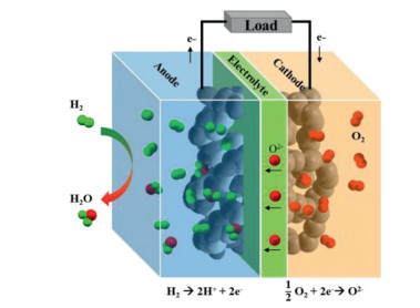
Solid oxide fuel cells (SOFCs) are considered sustainable high-efficient hydrogen-based energy production devices. The advantages of SOFCs include: (ⅰ) High power generation efficiency (> 60% for electricity, > 85% for electricity-heat cogeneration); (ⅱ) Widely adaptable to a variety of fuels, such as H2, biogas, nature gas, and methane; (ⅳ) Precious-metal catalysts are not necessary; (ⅴ) High volumetric power density and gravimetric power density (~10 W/cm3 and ~3 kW/kg) [1]. A SOFC consists of three key components: a dense electrolyte, a porous cathode and a porous anode. The working principle of SOFC is shown in Fig. 1. The hydrogen oxidation reaction (HOR) occurs at the anode and releases electrons. The generated electrons move to the anode surface and travel along the external circuit to the cathode. The oxygen reduction reaction (ORR) occurs at the active sites of the SOFC cathode and produces O2− ions. The O2− ions transfer to the cathode/electrolyte interface, and migrate in the electrolyte to the anode/electrolyte interface. The dissociated H+ ions in the active area of the anode combine with oxygen ions to finally produce H2O.

|
Download:
|
| Fig. 1. Schematic of a SOFC based on an O2− conducting electrolyte. | |
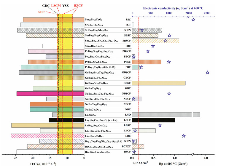
SOFCs are typically operated above 800 ℃ to ensure the good catalytic activity, acceptable ionic and electronic conductivity. High operating temperatures bring challenges on sealing issue, slow response to start up and cooling down, high total system cost and fast material degradation [2]. To solve the challenges, SOFCs working at intermediate temperature range (500–750 ℃) are desired (IT-SOFC). At IT temperature ranges, the performance and output power of SOFCs strongly depend on the ORR catalytic activity of cathode materials. In the ORR process, there are two critical steps, the reduction of oxygen at the surface active sites and the transport of oxygen ions away from the sites [3, 4]. In addition, the cathode materials should be chemically compatible, and have matched thermal expansion coefficient (TEC, α) with other components of SOFCs. Cathode materials should be in low cost and show long-term stability. There are two strategies to enhance the cathode performance: developing new materials and modifying the existing cathode materials. The conventional lanthanum strontium magnesium (LSM) cathode exhibits good performance above 800 ℃, but cannot work at the IT temperature range. As shown in Fig. 2, the TEC values of commonly used electrolytes such as yttrium stabilized zirconia (YSZ), strontium-/magnesium-doped lanthanum gallate (LSGM), gadolinia doped ceria (GDC), samarium-doped cerium (SDC) and BaZr0.8-CexY0.2O3-δ (BZCY) are in the range of 8.4 × 10⁻⁶ ~ 12.8 × 10⁻⁶ K−1 5-10. Among the cathode materials developed [8, 11-36, the commercial cathode of lanthanum strontium cobalt ferrite (LSCF) exhibits acceptable TEC (α100~600 ℃ = 15.3 × 10⁻⁶ K−1) [19, 20] and good catalytic activity at the IT temperatures, but the performance of LSCF drops dramatically with decreasing temperature due to Sr segregation [37]. Although new cathode materials with high ORR catalytic activity at low temperatures have been developed, such as Ba0.5Sr0.5Co0.8Fe0.2O3-δ (BSCF) and Sm0.5Sr0.5CoO3-δ (SSC), their thermal stability and compatibility are far from satisfactory [38]. Surface modification on some traditional commercialized cathode materials is considered to be a very promising strategy for IT-SOFCs cathodes with high ORR activity and durability [39].

|
Download:
|
| Fig. 2. The thermal expansion coefficient (bar chart in left), polarization resistance (bar chart in right) and electronic conductivity (blue star) of cathode materials at 600 ℃. The cathode materials are Ba0.5Sr0.5Co0.8Fe0.2O3-δ [11, 12], BaCo0.4Fe0.4Zr0.1Y0.1O3-δ (BCFZY) [13], Ba1-xCo0.7Fe0.2Nb0.1O3-δ (0≤x≤0.1) (BCFN) [14, 15]; La0.5Ba0.5CoO3-δ (LBC) [8, 16], La0.2Ba0.8Co0.7Fe0.3O3-δ (LBCF) [17], LaBa0.5Sr0.5Co2O5+δ (LBSC) [18], La0.6Sr0.4Co0.2Fe0.8O3-δ (x = 0.4) [19, 20], La2NiO4-δ (LNO) [21], NdBaCo2O5+δ (NBC) [22], NdBaCo1.5Fe0.5O5+δ (NBCF) [22], NdxBa1-xCo0.7Fe0.3O3-δ (NBCF) [17], NdBa0.5Sr0.5Co1.5Fe0.5O5+δ (NBSCF) [23, 24], GdBaCo2O5+δ (GBC) [22], GdBa0.5Sr0.5Co2O5+δ (GBSC) [25], GdBaCo1.5Fe0.5O5+δ (GBCF) [22], GdBa0.5Sr0.5Co1.5Fe0.5O5+δ (GBSCF) [26], PrBa1−xCo2O5+δ (0≤x≤0.08)(PBC) [27], PrBa0.5Sr0.5Co2O5+δ(PBSC) [28], Pr0.1Ba0.9Co0.7Fe0.3O3-δ(PBCF) [17], PrBa0.5Sr0.5Co1.5Fe0.5O5+δ (PBSCF) [29], Sm0.5Ba0.5CoO3-δ (SBC) [16, 30], Sm0.45Ba0.05Sr0.5Co0.8Fe0.2 O3-δ (SBSCF) [31], Sm0.35Ba0.15Sr0.5Co0.8Fe0.2 O3-δ (SBSCF) [31], SmBa0.5Sr0.5Co2O5+δ (SBSC) [25, 30], SrCo0.8Fe0.1Nb0.1O3-δ (SCFN) [32], SrCo0.9Ta0.1O3-δ(SCT) [33, 34], and Sm0.5Sr0.5CoO3 (SSC) [30, 35, 36]. The data for the thermal expansion coefficient of some common electrolyte materials are added in the bar chart in left. Electrolyte materials includes (Y2O3)0.08(ZrO2)0.92 (YSZ) [5], Ce0.8Sm0.2O2−δ (SDC) [6], GdxCe1-xO2−δ (GDC) (x = 0.1, 0.2) [5, 7], La0.8Sr0.2Ga0.8Mg0.2O3-δ (LSGM) [8], and BaZr0.8-xCexY0.2O3-δ (0.1≤x≤0.5) [9]. | |
Surface modification can be achieved by several techniques, including atomic layer deposition (ALD) [40, 41], pulsed laser deposition (PLD) [42] and solution infiltration. Among all the methods, infiltration/impregnation has been proved to be an effective method to construct SOFC in large scale without using any expensive equipment. The coating materials for infiltration are versatile and diverse [43]. In a typical infiltration process, a liquid solution containing the desired electrocatalyst precursors is introduced into a previously sintered porous backbone formed on the electrolyte. Infiltrated phases are formed upon calcination at a certain temperature. Performing the process once or several times can achieve a desired electrocatalyst loading within the pores of the porous backbones. In this minireview, an overview of the infiltration method will be provided, including the advantages and the disadvantages, the developed backbones, the coating materials, the existing issues and the perspectives.
2. The advantages of infiltration for IT-SOFC cathodesThe main advantages of infiltration for IT-SOFC cathodes include: (1) A wide range of active materials for surface coating are allowed to be used, even for the material which is not intrinsic a good cathode material due to TEC mismatch [8, 44]. For instance, the electronic conductivity of La0.5Ba0.5CoO3-δ (LBC) at 600 ℃ in air is relatively high (σ =1400 S/cm) as shown in Fig. 2. However, the application of LBC (α100-900 ℃ = 26.4 × 10⁻⁶ K−1) has been limited since its thermal incompatibility to most electrolyte materials (e.g., the TEC of La0.8Sr0.2Ga0.8Mg0.2O2.8 (LSGM) electrolyte is 12.0 × 10⁻⁶ K−1) [8]. LBC infiltrated LSGM is a thermally stable SOFC cathode. The TEC of LBC infiltrated LSGM (α100-900 ℃ =12.5 × 10⁻⁶ K−1) is close to that of the LSGM electrolyte, and even lower than LBC/LSGM composite (16.2 × 10⁻⁶ K−1). (2) Both the surface composition and the surface structure can be altered after surface infiltration [45, 46]. The catalyst coating enables the formation of nano structures with high electro-catalytic activity due to the increased surface area and the enlarged triple-phase boundary (TPB) areas [43, 47-50]. (3) The infiltration method allows relatively low heat treatment temperatures (< 900 ℃) which avoids the reduction of electrocatalyst/gas and electrocatalyst/ionic conductor (IC) interfacial areas induced by the crystal particle coarsening, and minimizes reactions between the infiltrated coating material and the backbone phase. (4) Infiltration can increase the durability of cathode and the tolerance to contamination as shown in Table 1 [20, 44, 51-60]. The degradation of SOFC cathode is commonly caused by the formation of secondary phases or the reactions of the segregated phases with the gas species [56]. These secondary phases result in decreased surface (bulk) electronic conductivity [61-65]. The contaminants such as CO2 [66], H2O [67], SO2 and H2S [56, 68] from environmental gas phases, the volatile chromium species [55, 58] from interconnector and boron species from the sealing materials [69] will accelerate the degradation [68]. The surface coating introduces a surface barrier layer, which suppresses the contamination to the surface of backbones. For instance, the segregated Sr on the LSCF cathode reacts with CrO3 to form insulating SrCrO4, which blocks the cathode ORR active sites. Surface coating can effectively suppress the surface segregation and improve the tolerance to chromium [55-71]. Yang et al. [44] found that SrCo0.9Ta0.1O3-δ acted as a Cr getter on the LSCF surface, which can mitigate Cr poisoning. In our previous work, we found that the infiltrated BaCO3 phase was almost inert to Cr species [20]. Currently most studies are focused on the Cr contamination of the cathode (Table 1) [20, 44, 51-60. In addition to Cr contamination, water also influences dramatically the durability of IT-SOFCs, especially for SOFCs based on proton conductors [72]. In future, more attentions should be paid on the water-tolerance performance of cathodes.
|
|
Table 1 Summary of infiltrated cathodes with enhanced performance and durability in the literature from 2012 to 2021. |

The infiltration method is a multi-step preparation process, consisting of the formation of a pre-sintering porous backbone and the deposition of an active catalyst (the infiltrate). The electrode performance is influenced by the composition and the morphology of both the infiltrate and the backbone. Pre-sintering of backbones at high temperatures is important since it ensures the high effective electron or oxygen-ion conduction. Backbones with continuous pore structure are favorable for infiltration. In addition, the backbone material should be thermally and chemically compatible with electrolyte to achieve the structure and chemical stability. Three types of common backbones are widely used, including the single-phase electrolyte-based backbone, the single-phase cathode-based backbone and the multi-phase (MP) composite backbone, as shown in Fig. 3.

|
Download:
|
| Fig. 3. The schematics of (a) an electrolyte-based backbone, (b) a single-phase electrode-based backbone, (c) a multi-phase composite backbone. The dense box stands for the electrolyte of SOFC. The porous structure stands for the infiltration backbones. EC represents electronic conductor, MIEC represents mixed ionic and electronic conductor. | |
Many researchers have studied the infiltration based on the backbones of electrolyte materials. The advantages of the electrolyte backbones include the facile preparation process and the compatible TEC with electrolyte. For example, the porous-dense-porous electrolyte backbone can be fabricated by one-step sintering of the green tape through pressing method or tape casting method [73]. The commonly used electrolyte-based backbone materials in SOFCs are ionic conductors (IC) including YSZ [73-77], SDC [78], GDC [79-81], LSGM [8, 82, 83], scandia-stabilized zirconia (ScSZ) [84], (Bi0.8Er0.2)2O3 (ESB) [2] and so on. Proton conductors (e.g., BaZr1-xYxO3-δ (BZY), BaCe1-xYxO3 (BCY) and doped BZY (BCY)) are also used as backbones in SOFCs based on proton-conducting electrolytes [85]. The infiltrated cathodes based on electrolyte backbones show relatively low Rp as shown in Table 2 [8, 73-83, 85, 86]. However, electrolyte-based backbones only conduct oxygen ions (or proton), sufficient amounts of electronically conductive materials must be infiltrated on electrolyte backbones by increasing the infiltration cycles to enhance the TPB length and to minimize the cathode electronic resistance. For instance, in some studies, researchers infiltrated up to 40 cycles or with catalyst amount over 45 wt% for sufficient loading [76, 79]. Therefore, the electrolyte backbone-based infiltration is typically a time-consuming multi-step process to infiltrate a considerable amount of material to ensure good electronic conductivity and sufficient TPB. The increased cost on raw materials such as some Co-containing infiltrates should not be ignored [87-89]. To reduce the infiltration time, new infiltration methods have been developed. For instance, The layer-by-layer (LbL)-assisted infiltration has been proposed to enhances surface wetting and to decrease the infiltration time [88]. The ultrasonic spray infiltration and the inject printing infiltration techniques are viable in industrial or commercial level to produce large-area catalyst coated cathodes for SOFCs with high and stable performances [90, 91]. Atomic layer deposition (ALD) has been used to fabricate conformal and uniform catalyst coatings with atomic-scale thickness on backbones but still far from large-scale production [40, 92]. The infiltration followed by chemically-assisted electrodeposition allows us to achieve desired loading of cathode catalyst with reduced infiltration cycles and without using any expensive equipment [93, 94].
|
|
Table 2 The performances of electrolyte-backbone based infiltrated cathodes in the past 10 years. |

The backbones made of cathode materials guarantee good electron transport. The infiltrations of various materials into either the porous electronic conductive (EC) or a mixed ionic–electronic conductive (MIEC) cathode backbones have been widely studied. Infiltrating ionic conductive materials into porous cathode backbones with low ionic conductivity, such as LSM or LaNi0.6Fe0.4O3-δ (LNF), can enhance the cathode ionic conduction and the effective three-phase boundary (TPB) area. At high temperatures (> 800 ℃), the LSM cathode has a high electronic conductivity, good chemical stability, high electrocatalytic activity, and matched TEC with many electrolyte materials [3, 95-98. However, as the operating temperature decreases, the polarization resistance (Rp) of LSM and LSM/YSZ cathodes increases significantly due to the sluggish ORR kinetics. Infiltrating catalysts into porous LSM backbones can improve the cathode performance of IT-SOFCs. Akbari et al. [99] infiltrated La2NiO4 into the LSM backbone, and found that Rp is reduced by 90.5% to 2.5 Ω cm2 at 650 ℃ and the ORR activation energy is decreased from 130 kJ/mol to 103 kJ/mol. However, the polarization resistance (or area specific resistance, ASR) is still much higher than the requirement for practical applications (< 0.15 Ω cm2) in IT-SOFCs [99, 100].
Different from electrolyte-based backbones and EC cathode-based backbones, MIEC cathode-based backbones show both good ionic conduction and electronic conduction, which broaden the types of infiltrated materials to even some non-electronic and non-ionic conducting oxides (e.g., CaO, MgO, BaO). LSCF has already been a commercial cathode at the intermediate temperatures from 600 ℃ to 750 ℃ [101, 102]. LSCF is also one of the widely used MIEC cathode backbones with both high ionic conductivity and good electronic conductivity and exhibits much better electrochemical performance as compared with most other cathode materials due to the relatively good ORR activity and the enlarged electrochemical active areas than traditional TPBs [102]. LSCF have matched TEC with most electrolyte materials [58]. All these properties make LSCF one of the most popular cathode candidates. However, at low temperatures (< 650 ℃), the relatively slow ORR kinetics limits the performance of LSCF cathode, resulting in increased Rp of the electrodes (> 0.15 Ω cm2). Therefore, considerable efforts have been made to develop catalysts on LSCF surface with high electrocatalytic ORR activity through infiltration. In addition, the long-term durability is another challenge for LSCF. The surface SrO segregation/enrichment alters the structure and composition of LSCF and is detrimental to the electro-catalytic activity and durability [95]. The segregated SrO readily reacts with contaminants such as vaporized Cr species from the Cr-containing alloy. The surface infiltration of LSCF can not only increase the surface activity, but also inhibit the segregation of Sr or radiality reaction of Sr with contaminants. Due to the good MIEC property of LSCF backbone, there is no need for multiple infiltration cycles for high-loading catalyst. For instance, Namgung et al. [103] reported a one-step-infiltration for discrete SSC nanoparticles on the LSCF backbone by adopting of cetrimonium bromide (CTAB)-amino acid (glycine) in the stock solution. Chen et al. [58, 104] demonstrated that using one-step infiltration process can significantly reduce the Rp of the LSCF cathode.
There are also some studies based on the infiltration of other MIEC cathode backbones, such as BSCF [53], PrBa0.5Sr0.5Co1.5Fe0.5O5+δ (PBSCF) [60], and Ba1−xCo0.7Fe0.2Nb0.1O3−δ (BCFN) [105]. These cathode backbones are not widely used due to the higher content of Co and mismatched TEC with electrolytes (Fig. 2, α > 20 × 10−6 K−1). Ruddlesden-Popper perovskite like La2NiO4-δ (LNO) has matched TEC with common electrolytes [106, 107], the low-temperature performance of LNO cathodes has been improved by infiltration, but the performance still cannot meet the pratical requirements due to the large polarization resistance of the pristine LNO at low temperatures (Fig. 2, Rp =3.86 Ω cm2 at 600 ℃) [21]. In addition to the oxide cathodes mentioned above, the metal cathodes such as Ag are also used as backbones for infiltration. Metal backbones own matched TEC with other parts, high electrical conductivity and good formability. However, metal backbones are chemically unstable in oxidative atmosphere.
3.3. Multi-phase composite backbonesThe composite backbones include IC-EC, IC-MIEC and EC-MIEC composites [108]. Compared with the single-phase IC electrolyte backbones and the single-phase EC cathode backbones, IC-EC composite backbones (e.g., LSM/YSZ [109-111]) have prolonged three-phase boundary. Wang et al. [112] co-infiltrated PdO and ZrO2 on the LSM/YSZ electrode and obtained a polarization resistance of 0.40 Ω cm2 at 750 ℃, which was 1/10 of that for bare LSM/YSZ cathode. For composite backbones, the chemical compatibility between composite materials needs to be considered. For example, many researchers found that La from LSM reacts with Zr from YSZ phase, forming an electrically insulating pyrochlore phase (La2Zr2O7) as the sintering temperature is higher than 900 ℃ [113-116]. In recent years, extensive studies on composite backbones are based on GDC or SDC. GDC and SDC show less active with La in IC-MIEC composites. The combination of LSCF and GDC as backbone has been proved to be an ideal backbone to reduce the operating temperature [44, 117, 118].
In summary, different types of infiltrated backbones are introduced in this section. For the electrolyte backbones, reducing the infiltration time is desired by developing new infiltration methods. For the single-phase cathode-based backbones, most studies still focus on conventional cathode materials such as LSCF. Other MIEC backbones are restricted by either their high price or their intrinsic properties. For the multi-phase composite backbones, since this type of backbones have elongated TPBs, their performances are very promising. Since the research on such backbones are still inadequate, there is a huge space to develop high-performance cathodes by infiltrating on such backbones.
4. Catalysts for surface infiltrationSeveral types of catalysts have been developed, including precious metals, oxygen ion-conducting oxides [55, 119, 120], mixed ionic and electronic conductors [70, 121, 122], non-ionic and non-electronic conducting oxides [57, 123]. Besides, according to the chemical composition of the electro-catalysts, the catalyst on the surface can be divided into single-phase catalysts and multi-phase catalysts [104, 124]. The morphologies of the infiltrated catalysts on the surface of cathodes are diverse, including uniform coating layers, discrete nanoparticles, and conformal coating with discrete particles, as shown in Fig. 4. The discrete nanoparticles have larger surface area for ORR than conformal coatings. However, the conformal coating has better durability and contaminants tolerance than the discrete nanoparticles coating since the conformal coatings can cover the entire cathode surface and avoid the coarsening issue of nanoparticles [44, 58]. The conformal coating with nanoparticles can achieve both high activity and durability than the aforementioned coatings.

|
Download:
|
| Fig. 4. Schematics of the structures of the backbone and coatings. From (a) an as-fired electrode backbone to three typical morphologies of infiltrated electrode after thermal treatment: (b) particle deposition, (c) thin film coating, and (d) conformal coating with nanoparticles. | |
Noble metals (e.g., Ag, Pd, Rh and Pt) have been used as catalysts coating on the cathodes due to the high catalytic activity, high oxygen solubility and permeability [125, 126]. In addition, precious metals such as silver can minimize the ohmic resistance due to their excellent electronic conductivity. Ag infiltration is frequently reported to enhance the performance of the cathodes such as LSM [127], LSCF [128] and LSCF/YSZ [129]. However, the agglomeration of low-melting-point Ag decreases metal surface area and deteriorates the long-term stability of Ag-impregnated cathodes [130]. To solve the agglomeration problem, it is found that co-infiltration of Ag and CeO2 is an efficient way to inhibit Ag agglomeration on the surface of cathodes [130, 131]. CeO2 has a high melting point which makes it stable under high temperature. Hence, ceria nanoparticles serving as a physical barrier against Ag agglomeration to ensure the excellent long-term stability. Pd and Pt have also been infiltrated on cathode surfaces [127, 131, 132]. Adding a small amount of Pd catalyst (0.08 mg/cm2) can reduce the overpotential of LSM cathodes. Jiang et al. [127] found that co-infiltration of Pd with either Ag (Pd0.8Ag0.2) or Co (Pd0.95Co0.05) into porous LSM can enhance both the ORR activity and the stability. For instance, the initial overpotential for Pd0.8Ag0.2 coated LSM (≈ 20 mV) is reduced by 8% as compared with the pure Pd coated LSM measured at 850 ℃ and 200 mA/cm2. The co-infiltration shows negligible degradation within the initial 2500 minutes at 850 ℃. The main drawbacks of precious metals are their high cost and the low tolerance to contaminations (e.g., CO and H2S) [133]. In recent years, most studies are focused on noble-metal-free coating materials since the performances of the cathodes coated with noble metals are commonly not better than the performances of noble-metal-free cathodes.
4.2. Oxygen ion conducting oxidesIon-conducting oxides including YSZ [134], SDC [119] and GDC [55, 120] were introduced as coating materials by the infiltration/impregnation techniques. When the electrolyte materials are used as coating materials, the backbones should be electronic conductive, or mixed ionic and electronic conductive. The introduction of the ionic conductor is expected to improve the electrode ionic conductivity of the cathode and increase the TPB. Wang et al. [134] infiltrated electrolytes (YSZ, SDC) into the LSM backbone and studied their effect on the surface exchange coefficient (K) by electrical conductivity relaxation (ECR). They found that IC nanoparticles on LSM promote the surface exchange kinetics. The oxygen surface exchange coefficient at 1000 ℃ for YSZ coated LSM is 2.45 × 10⁻⁴ cm/s, which is 2.7 times higher than that for bare LSM. Moreover, the K for SDC coated LSM (7.92 × 10⁻⁴ cm/s) is 3 times higher than that for YSZ coated LSM. Jiang group [55, 135] and dos Santos-Gómez et al. [120] coated Gd0.2Ce0.8O1.9 on the LSCF surface through infiltration. They found that the electrochemical performance and the Cr-tolerance property of the coated cathode were both improved [55, 120]. The GDC coating serves as a barrier layer to enhance the tolerance of LSCF against chromium deposition and poisoning, but the performance in wet air was not given.
4.3. EC and MIEC conductorsInfiltrated electronic conducting phases can act as catalysts for the ORR [122, 136]. Despite LSM is not applicable for IT-SOFC cathodes or backbones, the commercial cobalt-free LSM was found to be a good infiltrating catalyst. Huang et al. [2] infiltrated La0.85Sr0.15MnO3±δ into the Bi1.6Er0.4O3 backbone. The cell with the coated cathode exhibited a maximum power density (MPD) of 1.18 W cm−2 (1.8 times higher as compared with the non-coated cell) and a low Rp (0.107 Ω cm2) at 600 ℃. Kang et al. [51] infiltrated La1-xSrxMnO3-δ into the LaNi6Fe4O3-δ backbone. They found that the Rp was greatly reduced by 77.9% to 0.49 Ω cm2 at 700 ℃. However, the infiltrated LSM catalyst shows the largest Rp than the infiltrated materials including LaNi1-xFexO3-δ, LaxSr1-xCoyFe1-yO3-δ (LSCF), Gd1-xCexO2-δ (GDC) and Pr6O11.
Compared with IC materials, MIEC catalyst coated cathodes have been studied extensively (e.g., LSCF [121], Sm0.5Sr0.5CoO3−δ [121] and PrSrCoMnO6−δ [70]). MIEC materials such as Sm0.5Sr0.5CoO3−δ [121], SrCo0.9Ta0.1O3-δ (SCT) [44] and LnBaCo2O3-δ [8, 137] have comparable electronic conductivity, higher oxygen diffusion/exchange coefficient, better ORR activity and durability than LSCF, but cannot be directly used as cathodes due to the mismatched TEC with most electrolytes [8]. In addition, the use of above materials in large amounts is not cost competitive due to the expensive component (e.g., Co, Sm). But the low-loading infiltrated catalysts can reduce the TEC mismatch and save the cost on the materials [8].
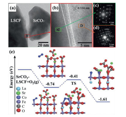
4.4. Non-electronic and non-ionic conducting oxideThe non-electronic and non-ionic conducting phases, including alkali-earth metal compounds (CaO [138], MgO [139], BaO [57], BaCO3 [123, 140, 141] and SrCO3 [142, 143]) or transition metal oxide (NiO [144], CuO [117]), have been reported as coating materials on the backbones of MIEC or composite materials. These infiltrating materials are considered ORR inactive, but they may influence backbones. Bidrawn et al. [145] fabricated (La, Sr)FeO3 (LSF) infiltrated YSZ (LSF-YSZ) and calcined at 1100 ℃. Then LSF-YSZ backbone is infiltrated by CaO (or K2O) and followed by re-calcined at 700 ℃. They found that the CaO (or K2O) infiltrated cathodes exhibited better performance than the pristine cathode, but the mechanism is not clear. Xia groups infiltrated LSCF with several inert phase materials, which showed both decreased polarization resistance and improved stability in air or contaminants (e.g., chromium, H2O) due to the increased chemical oxygen surface exchange coefficient [123, 141, 143]. Mutoro et al. [146] proposed that the increased ORR kinetics is attributed to the hetero-interface of Ruddlesden–Popper (La, Sr)2CoO4-δ between La0.8Sr0.2CoO3 and inactive Sr-phases (SrCO3/Sr(OH)2/SrO). In the report of Li et al. [143], SrCO3 was infiltrated on LSCF. As shown from the high resolution transmission electron microscopy (HRTEM) and selected area electron diffraction (SAED) images in Figs. 5a-d, no obvious solid-state reactions or new phases occur at the interface between SrCO3 and LSCF. The density functional theory (DFT) calculations in Fig. 5e indicates that SrCO3 can influence the charge density distribution of Fe and Co, which increases the O2 adsorption energy from -0.32 eV to -0.74 eV and decreases the dissociation energy barrier of O2 molecule from 1.01 eV to 0.33 eV on SrCO3 coated LSCF. Chen et al. [92, 147] investigated BaO coated PrBa0.8Ca0.2Co2O5+δ (PBCC) and found that barium cobaltite in-situ formed on the PBCC surface, which contributed to the enhanced ORR kinetics.

|
Download:
|
| Fig. 5. (a, b) HRTEM images and (c, d) SAED patterns of SrCO3 coated LSCF. (e) The dissociated energy profiles of the O2 molecule on the SrCO3-modified LSCF. Blue balls and red balls represent the adsorbed oxygen molecules and the crystal oxygen. Copied with the permission [143]. Copyright 2017, Royal Society of Chemistry. | |
Inert oxide is in low cost compared with other infiltration species. However, inactive oxides must be coated as discrete particles rather than conformal coating, otherwise inert oxides will block ORR reactions. The Sr segregation from LSCF cannot be well suppressed by the discrete inert oxide particles. The inert oxides coated LSCF cathodes still suffer from high polarization resistances (> 0.15 Ω cm2 at 650 ℃) [148, 149].
4.5. Multi-phase catalystMulti-phase catalysts coatings have been proved to be more efficient than single-phase catalysts. The morphology of the multi-phase catalyst infiltrated cathodes could be obtained by carefully controlling the composition and wettability of the solution, the drying rate of infiltrating process, as well as the firing temperature. There are mainly two ways for multi-phase catalyst infiltration: co-infiltrating different materials at once (or separately), and in-situ decomposing. Seyed et al. [131] co-infiltrated Ag-Ceria catalysts into the LSM backbone. The infiltrated cathode showed decreased polarization among all the single-phase catalysts (Ag, Ceria, LSF-coated LSM) due to the high electronic conductivity of Ag and oxygen vacancy rich ceria. Tong et al. [150] co-infiltrated GDC and Pr6O11 into the porous cobalt-free (La0.6Sr0.4)0.98FeO3-δ (LSF) backbone. The solution for infiltration contains Pr(NO3)3 and colloidal GDC nanoparticles. At 750 ℃, the Rp of GDC and Pr6O11 co-infiltrated LSF cathode (0.017 Ω cm2) is about one tenth of the bare LSF (0.197 Ω cm2), one fifth of GDC coated LSF (0.089 Ω cm2), and 60% of the Pr6O11-coated LSF (0.028 Ω cm2). The unique activity of the co-infiltrated LSF electrode is attributed to the accelerated oxygen surface exchange kinetics by Pr6O11, and enhanced active surface area by GDC nanoporous architecture.
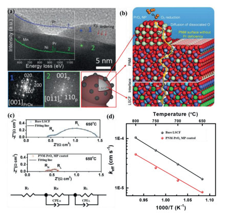
In-situ exsolving, segregating or decomposing oxide from the bulk coating phase is another strategy for MP catalysts. Chen et al. infiltrated the catalyst precursor solution with a stoichiometric ratio of Pr2Ni0.5Mn0.5O4+δ onto the porous LSCF cathode surface 58-58. A perovskite PrNi0.5Mn0.5O3(PNM) conformal coating with exsoluted PrOx nano-particles (PNM-PrOx MP) on LSCF are formed (Fig. 6a) during the cell start-up process at the fire temperature of 800 ℃. The fast Fourier transform (FFT) pattern at location 1 indicates that PrOx nanoparticles are rich in oxygen vacancies. From the DFT calculations, the O vacancy energy for PrOx is 1.04 eV, which is smaller than that for LSCF (2.38 eV). The smaller O vacancy energy promotes the O2 reduction and the diffusion of dissociated O as illustrated in Fig. 6b. The O migration barrier for PNM structure with Pr deficiency is 0.45 eV, which is much lower than that for bulk PNM structure (1.26 eV). This indicates that PNM with Pr deficiency facilitates the oxygen-ion transfer (Fig. 6b). EIS and ECR measurement reveal that the PNM-PrOx MP catalyst accelerates the oxygen-ion transfer and the oxygen dissociation-absorption processes [124, 151]. For example, by coating PNM-PrOx MP catalyst on bare LSCF, the Rp is significantly reduced from 1.02 Ω cm2 to 0.25 Ω cm2 at 650 ℃ as shown in Fig. 6c. The EIS spectra is fitted by the equivalent circuit, where the high frequency arc resistance (RH) and the low frequency arc resistance (RL) correspond to the oxygen-ion transfer process and the oxygen dissociation absorption process, respectively. Compared with bare LSCF, both RH and RL is reduced in the cathode with PNM-PrOx MP coated. At 650 ℃, the Keff for PNM-PrOx MP coated LSCF (1.51 × 10⁻⁵ cm/s) is twice of that for bare LSCF (Fig. 6d), indicating that the oxygen dissociation-absorption process (oxygen surface exchange) is accelerated. More importantly, the PNM-PrOx MP catalyst enhances significantly the tolerance to Cr poisoning even in humidified air with a degrading rate of 0.0434% h−1 at 0.7 V in 3% H2O, which is 1/10 of that for the bare LSCF cathode [58]. Similarly, PrCoO3-x(PCO) and BaCoO3-x (BCO) nanoparticles segregated from the conformal PBCC [104], SrMoO4 (SM) phase exsolved from the Sr2MnMoO5-δ (SMM) phase have been reported [152].

|
Download:
|
| Fig. 6. (a) High-resolution TEM image of PrO exsoluted from PNM as SOFC cathode. The insets are the FFT patterns from the exsoluted nanoparticles (location 1) and the conformal coating (location 2), and the EELS spectra from location 1 and 2. (b) Schematic representation of the ORR mechanism on the MP (PrO/PNM) coated LSCF cathode. (a, b) Copied with permission [104]. Copyright 2018, Elsevier. (c) Impedance spectra of single cells at 650 ℃ and the equivalent circuit R1(RHCPEH)(RLCPEL) used to fit the spectra. (d) Plots of the surface exchange coefficients (K) as function of temperatures. (c, d) Copied with permission [151]. Copyright 2018, Elsevier. | |
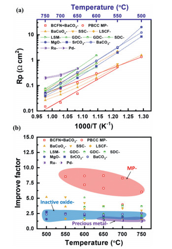
Fig. 7a compares Rp for LSCF cathodes infiltrated with various materials, including MP catalysts (PBCC MP catalyst [104], Ba1-xCoFe0.2NbO3-δ (BCFN) and BaCO3 [20]), MIEC conductors (SSC [121], LSCF [121], BaCoOx [59]), ionic conductors (SDC [119], GDC [55, 135]), electronic conductors (LSM [153]), inactive oxides (MgO [139], SrCO3 [143], BaCO3 [123]) and precious metal (Rh and Pd [126]). MP coated LSCF exhibits a lower Rp than most of the cathodes. Improving factor (fp), the ratio of the polarization resistance of the bare cathode to that of the coated cathode [97], is used to describe the performance improvement. As shown in Fig. 7b, among all the coated LSCF, MP coated LSCF shows much higher fp as compared with the other infiltration species. The improving factor for infiltrated LSCF follows the order: MP > MIEC > inactive oxide or precious metal. This indicates that multi-phase catalysts are advantageous over the other infiltration species. Among the MP coated cathodes, the fp for BCFN and BaCO3 coated LSCF at 650 ℃ (fp = 8.66) shows the highest value among all the catalysts.

|
Download:
|
| Fig. 7. (a) The temperature dependance of Rp and (b) the improving factor for LSCF cathodes coated with different materials. PBCC MP coated LSCF is reproduced with permission [104]. Copyright 2018, Elsevier. BCFN and BaCO3 multiphase coated LSCF is reproduced with permission [20]. Copyright 2021, Wiley-VCH GmbH. Both SSC coated and LSCF coated are reproduced with permission [121]. Copyright 2009, Elsevier. BaCoO coated is reproduced with permission [59]. Copyright 2020, Elsevier. SDC coated is reproduced with permission [119]. Copyright 2010, Elsevier. GDC coated is reproduced with permission [55, 135]. Copyright Elsevier. LSM coated is reproduced with permission [153]. Copyright 2013, Elsevier. MgO coated is reproduced with permission [139]. Copyright 2018, Elsevier. SrCO3 coated is reproduced with permission [143]. Copyright 2017, Wiley-VCH GmbH. BaCO3 coated is reproduced with permission [123]. Copyright 2016, Wiley-VCH GmbH. Both Rh coated and Pd coated are reproduced with permission [126]. Copyright 2008, Elsevier. | |
The ORR activity and the tolerance to contaminations (Cr and H2O) are significantly improved by the MP coating. Another example through utilizing the instability of the coating materials on the backbone to in-situ form MP catalyst was from Nicollet et al. [154] They infiltrated Pr2NiO4+δ into the GDC backbone and obtained Pr6O11 and NiO phases at 900 ℃ in N2 since GDC backbone inhibited the crystallization of Pr2NiO4+δ. The Pr6O11 and NiO phases coated cathode exhibited a low Rp of 0.078 Ω cm2 at 600 ℃ [152, 154]. To date, there are few studies on how to control the distribution and size of the exsolved nanoparticles. Due to the complexity of the structure and the component of MP coating materials, it is difficult to reveal the ORR catalytic mechanism. In the future, more MP catalyst materials with different morphologies and compositions with specific properties need to be exploited.
To summarize section 4, different types of infiltrated catalysts or materials are overviewed. The correlations among the composition, structure and performance of infiltrated catalysts or materials are illustrated according to the classification of the infiltrated catalysts. The MP catalysts are highly desired to developed high-performance and durable cathodes. The variety of backbones, morphologies and compositions greatly broaden the application of infiltrated cathodes. By careful design, the catalyst for surface infiltration can greatly enhance the catalytic activity at low and intermediate temperatures and improve the tolerance to contaminations.
5. Summary and prospectiveInfiltration on the existing backbones has been proved to be an efficient method to construct highly active and durable cathodes. The infiltration process and the performance depend on many factors. In this mini-review, we emphases on the backbones and the coating materials. MIEC and composite backbones are more competitive as compared with the electrolyte backbones due to the increased TPB areas. The choice of the infiltrate material is versatile, including precious metals, oxygen ion-conducting oxides, mixed ionic and electronic conductors, and non-ionic and non-electronic conducting oxides. In particular, infiltrated multi-phase catalysts on LSCF backbone exhibit better ORR catalytic activity and thermal/chemical stability. The infiltration method allows us to use a wide range of infiltrated materials into various backbones, and endows the coated cathodes with desired properties.
Although the infiltrated cathodes have many advantages, these challenges should be addressed in future research: (1) The infiltration cycles should be largely reduced and large-scale infiltration techniques need to be developed. (2) Due to the limitations of the measurable scale, the underlying mechanism of the original performance improvement and the heterostructure between the infiltration materials and the backbones is still unclear. Further investigation on ex-situ and in-situ characterization are needed to illustrate the reactions or catalytic mechanisms. (3) The composition and morphology of the infiltrated cathode surface should be rationally designed and well controlled, such as the thickness, the distribution of the particles and the multi-phase components. The correlation between the composition/structure of the infiltrated material and the cathode performance should be explored extensively. (4) New infiltrated materials should be explored, such as semiconductor materials. For instance, TiO2 is found to enhance catalytic activity of the anode towards simulated biogas and the coking resistance due to the infrared light driven photocatalytic removal of deposited carbon [155]. However, there are few studies on semiconductors as infiltration materials. (5) The infiltration concept can be expanded to other electrochemical energy devices. For example, the infiltrated electrodes can also be applied in solid electrolysis cells, metal-air batteries, photo-catalysis devices and so on.
Declaration of competing interestThe authors declare no competing financial interest.
AcknowledgmentsThis work was supported by the Natural Science foundation of China (No. 51972043), Foundation of Yangtze Delta Region Institute (HuZhou) of UESTC, China (Nos. U03210010 and U03210028), the Sichuan-Hong Kong Collaborative Research Fund (No. 2021YFH0184), the Application Fundamental Research Project of Sichuan Province (No. 2019YJ0169), and the New Scholar Fund of UESTC.
| [1] |
E.D. Wachsman, K.T. Lee, Science 334 (2011) 935-939. DOI:10.1126/science.1204090 |
| [2] |
Y.L. Huang, A.M. Hussain, I.A. Robinson, E.D. Wachsman, ACS Appl. Mater. Interfaces 10 (2018) 28635-28643. DOI:10.1021/acsami.8b08911 |
| [3] |
Y. Chen, S. Yoo, K. Pei, et al., Adv. Funct. Mater. 28 (2018) 1704907. DOI:10.1002/adfm.201704907 |
| [4] |
B. Wang, X. Cui, J. Huang, R. Cao, Q. Zhang, Chin. Chem. Lett. 29 (2018) 1757-1767. DOI:10.1016/j.cclet.2018.11.021 |
| [5] |
T. Jiang, Z. Wang, B. Ren, et al., J. Power Sources 247 (2014) 858-864. DOI:10.1016/j.jpowsour.2013.09.034 |
| [6] |
Q. Xu, D.P. Huang, F. Zhang, et al., J. Alloys Compd. 454 (2008) 460-465. DOI:10.1016/j.jallcom.2006.12.132 |
| [7] |
C.R. Dyck, Z.B.H. Yu, V.D. Krstic, Solid State Ion. 171 (2004) 17-23. DOI:10.1016/j.ssi.2004.02.014 |
| [8] |
C. Setevich, S. Larrondo, F. Prado, Ceram. Int. 44 (2018) 16851-16858. DOI:10.1016/j.ceramint.2018.06.121 |
| [9] |
Y.G. Lyagaeva, D.A. Medvedev, A.K. Demin, P. Tsiakaras, O.G. Reznitskikh, Phys. Solid State 57 (2015) 285-289. DOI:10.1134/S1063783415020250 |
| [10] |
L. Zhang, S. Yang, S. Zhang, Y. Yang, Int. J. Hydrogen Energy 44 (2019) 27921-27929. DOI:10.1016/j.ijhydene.2019.09.057 |
| [11] |
Y. Song, Y. Chen, W. Wang, et al., Joule 3 (2019) 2842-2853. DOI:10.1016/j.joule.2019.07.004 |
| [12] |
Z. Shao, S.M. Haile, Nature 431 (2004) 170. DOI:10.1038/nature02863 |
| [13] |
C. Duan, D. Hook, Y. Chen, J. Tong, R. O'Hayre, Energ. Environ. Sci. 10 (2017) 176-182. DOI:10.1039/C6EE01915C |
| [14] |
Z. Yang, M. Han, P. Zhu, F. Zhao, F. Chen, Int. J. Hydrogen Energy 36 (2011) 9162-9168. DOI:10.1016/j.ijhydene.2011.04.045 |
| [15] |
Z. Yang, Y. Liu, Y. Chen, et al., Int. J. Hydrogen Energy 42 (2017) 6997-7002. DOI:10.1016/j.ijhydene.2016.11.045 |
| [16] |
J.H. Kim, A. Manthiram, J. Electrochem. Soc. 155 (2008) B385. DOI:10.1149/1.2839028 |
| [17] |
W. Zhang, L. Zhang, K. Guan, et al., J. Power Sources 446 (2020) 227360. DOI:10.1016/j.jpowsour.2019.227360 |
| [18] |
C. Yao, H. Zhang, X. Liu, et al., J. Solid State Chem. 265 (2018) 72-78. DOI:10.1016/j.jssc.2018.05.028 |
| [19] |
L.W. Tai, M.M. Nasrallah, H.U. Anderson, D.M. Sparlin, S.R. Sehlin, Solid State Ion. 76 (1995) 273-283. DOI:10.1016/0167-2738(94)00245-N |
| [20] |
Y. Niu, Y. Zhou, W. Lv, et al., Adv. Fun. Mater. 31 (2021) 2010034. |
| [21] |
Y. Liu, J. Shuang, X. Tong, S. Yang, Y. Yang, M. Wei, Electrochim. Acta 298 (2019) 852-857. DOI:10.1016/j.electacta.2018.12.115 |
| [22] |
Y.N. Kim, J.H. Kim, A. Manthiram, J. Power Sources 195 (2010) 6411-6419. DOI:10.1016/j.jpowsour.2010.03.100 |
| [23] |
J.S. Shin, H. Park, K. Park, et al., J. Mater. Chem. A 9 (2021) 607-621. DOI:10.1039/d0ta11000k |
| [24] |
Q. Yang, D. Tian, R. Liu, et al., Int. J. Hydrogen Energy 46 (2021) 5630-5641. DOI:10.1016/j.ijhydene.2020.11.031 |
| [25] |
J.H. Kim, M. Cassidy, J.T.S. Irvine, J. Bae, J. Electrochem. Soc. 156 (2009) B682. DOI:10.1149/1.3110989 |
| [26] |
C. Kuroda, K. Zheng, K. Świerczek, Int. J. Hydrogen Energy 38 (2013) 1027-1038. DOI:10.1016/j.ijhydene.2012.10.085 |
| [27] |
S. Pang, X. Jiang, X. Li, Q. Wang, Z. Su, J. Power Sources 204 (2012) 53-59. DOI:10.1016/j.jpowsour.2012.01.034 |
| [28] |
B. Wang, G. Long, Y. Ji, M. Pang, X. Meng, J. Alloys Compd. 606 (2014) 92-96. DOI:10.1016/j.jallcom.2014.03.138 |
| [29] |
L. Jiang, T. Wei, R. Zeng, W.X. Zhang, Y.H. Huang, J. Power Sources 232 (2013) 279-285. DOI:10.1016/j.jpowsour.2013.01.064 |
| [30] |
A. Jun, J. Kim, J. Shin, G. Kim, Int. J. Hydrogen Energy 37 (2012) 18381-18388. DOI:10.1016/j.ijhydene.2012.09.048 |
| [31] |
J. Gao, X. Song, F. Zhou, S. An, Y. Tian, J. Power Sources 218 (2012) 383-392. DOI:10.1016/j.jpowsour.2012.05.070 |
| [32] |
S. Wang, F. Jin, L. Li, et al., Int. J. Hydrogen Energy 42 (2017) 4465-4477. DOI:10.1016/j.ijhydene.2016.11.015 |
| [33] |
X. Ding, Z. Gao, D. Ding, et al., Appl. Catal. B 243 (2019) 546-555. DOI:10.1016/j.apcatb.2018.10.075 |
| [34] |
Q. Zhou, T. Wei, Y. Shi, et al., Curr. Appl. Phys. 12 (2012) 1092-1095. DOI:10.1016/j.cap.2012.01.012 |
| [35] |
J. Dailly, G. Taillades, M. Ancelin, P. Pers, M. Marrony, J. Power Sources 361 (2017) 221-226. DOI:10.1016/j.jpowsour.2017.06.089 |
| [36] |
S. Yang, T. He, Q. He, J. Alloys Compd. 450 (2008) 400-404. DOI:10.1016/j.jallcom.2006.10.147 |
| [37] |
X. Xi, X. Chen, G. Hou, et al., Ceram. Int. 40 (2014) 13753-13756. DOI:10.1016/j.ceramint.2014.05.082 |
| [38] |
H. Tang, Z. Gong, Y. Wu, Z. Jin, W. Liu, Int. J. Hydrogen Energy 43 (2018) 19749-19756. DOI:10.1016/j.ijhydene.2018.09.008 |
| [39] |
C. Zhao, Y. Li, W. Zhang, et al., Energ. Environ. Sci. 13 (2020) 53-85. DOI:10.1039/c9ee02230a |
| [40] |
Y. Chen, L. Liang, S.A. Paredes Navia, et al., ACS Catal. 9 (2019) 6664-6671. DOI:10.1021/acscatal.9b00811 |
| [41] |
A. Seong, J. Kim, O. Kwon, et al., Nano Energy 71 (2020) 104564. DOI:10.1016/j.nanoen.2020.104564 |
| [42] |
D. Lee, Y. Lee, A. Grimaud, et al., J. Phys. Chem. C 118 (2014) 14326-14334. DOI:10.1021/jp502192m |
| [43] |
T. Lee, L. Fan, C. Yu, F.E. Wiria, P. Su, J. Mater. Chem. A 6 (2018) 7357-7363. DOI:10.1039/C8TA01104D |
| [44] |
T. Yang, Y. Wen, T. Wu, N. Xu, K. Huang, J. Mater. Chem. A 8 (2020) 82-86. DOI:10.1039/C9TA11657E |
| [45] |
W. Lee, J.W. Han, Y. Chen, Z. Cai, B. Yildiz, J. Am. Chem. Soc. 135 (2013) 7909-7925. DOI:10.1021/ja3125349 |
| [46] |
Y. Li, W. Zhang, Y. Zheng, et al., Chem. Soc. Rev. 46 (2017) 6345-6378. DOI:10.1039/C7CS00120G |
| [47] |
C. Ni, M. Cassidy, J.T.S. Irvine, J. Eur. Ceram. Soc. 38 (2018) 5463-5470. DOI:10.1016/j.jeurceramsoc.2018.08.026 |
| [48] |
Y. Lu, P. Gasper, U.B. Pal, S. Gopalan, S.N. Basu, J. Power Sources 396 (2018) 257-264. DOI:10.1016/j.jpowsour.2018.06.027 |
| [49] |
M. Kishimoto, M. Lomberg, E. Ruiz-Trejo, N.P. Brandon, J. Power Sources 266 (2014) 291-295. DOI:10.1016/j.jpowsour.2014.05.038 |
| [50] |
M.C. Tucker, G.Y. Lau, C.P. Jacobson, L.C. DeJonghe, S.J. Visco, J. Power Sources 171 (2007) 477-482. DOI:10.1016/j.jpowsour.2007.06.076 |
| [51] |
H. Kang, S. Grewal, H. Li, M. Lee, J. Electrochem. Soc. 166 (2019) F255-F263. DOI:10.1149/2.0421904jes |
| [52] |
Y. Choe, J. Seo, K. Lee, M. Lee, H. Hwang, T. Nonferr, Metal Soc. 26 (2016) 1367-1372. |
| [53] |
P. Qiu, A. Wang, H. Zheng, et al., Int. J. Hydrogen Energy 43 (2018) 20696-20703. DOI:10.1016/j.ijhydene.2018.09.154 |
| [54] |
B. Huang, X. Zhu, R. Ren, et al., J. Power Sources 216 (2012) 89-98. DOI:10.1016/j.jpowsour.2012.05.058 |
| [55] |
L. Zhao, S. Amarasinghe, S.P. Jiang, Electrochem. Commun. 37 (2013) 84-87. DOI:10.1016/j.elecom.2013.10.019 |
| [56] |
C. Wang, D. Luo, S. Jiang, B. Lin, J. Phys. D Appl. Phys. 51 (2018) 435502. DOI:10.1088/1361-6463/aadf4c |
| [57] |
K. Chen, N. Ai, K.M. O'Donnell, S.P. Jiang, Phys. Chem. Chem. Phys. 17 (2015) 4870-4874. DOI:10.1039/C4CP04172K |
| [58] |
Y. Chen, S. Yoo, X. Li, et al., Nano Energy 47 (2018) 474-480. DOI:10.1016/j.nanoen.2018.03.043 |
| [59] |
K. Pei, Y. Zhou, K. Xu, et al., Nano Energy 72 (2020) 104704. DOI:10.1016/j.nanoen.2020.104704 |
| [60] |
J. Li, J. Li, D. Yan, et al., Electrochim. Acta 270 (2018) 294-301. DOI:10.1051/jnwpu/20183620294 |
| [61] |
K. Chen, N. Li, N. Ai, et al., ACS Appl. Mater. Interfaces 8 (2016) 31729-31737. DOI:10.1021/acsami.6b11665 |
| [62] |
U. Anjum, M. Agarwal, T.S. Khan, M.A. Haider, Ionics 26 (2019) 1307-1314. |
| [63] |
M. Niania, R. Podor, T.B. Britton, et al., J. Mater. Chem. A 6 (2018) 14120-14135. DOI:10.1039/C8TA01341A |
| [64] |
B. Wei, M. Schroeder, M. Martin, ACS Appl. Mater. Interfaces 10 (2018) 8621-8629. DOI:10.1021/acsami.7b17881 |
| [65] |
Y. Yu, K.F. Ludwig, J.C. Woicik, et al., ACS Appl. Mater. Interfaces 8 (2016) 26704-26711. DOI:10.1021/acsami.6b07118 |
| [66] |
L. Yang, Y. Choi, W. Qin, et al., Nat. Commun. 2 (2011) 357. DOI:10.1109/EPEC.2011.6070225 |
| [67] |
C. Sun, S. Yang, Y. Lu, et al., J. Power Sources 449 (2020) 227498. DOI:10.1016/j.jpowsour.2019.227498 |
| [68] |
J. Druce, H. Téllez, J. Hyodo, MRS Bull. 39 (2014) 810-815. DOI:10.1557/mrs.2014.170 |
| [69] |
Q. Zhang, S. Tan, M. Ren, et al., J. Power Sources 383 (2018) 34-41. DOI:10.1016/j.jpowsour.2018.02.057 |
| [70] |
D. Ding, M. Liu, Z. Liu, et al., Adv. Energy Mater. 3 (2013) 1149-1154. DOI:10.1002/aenm.201200984 |
| [71] |
M.K. Stodolny, B.A. Boukamp, D.H.A. Blank, F.P.F. van Berkel, J. Power Sources 209 (2012) 120-129. DOI:10.1016/j.jpowsour.2012.02.083 |
| [72] |
Y. Zhou, E. Liu, Y. Chen, et al., ACS Energy Lett. (2021) 1511-1520. DOI:10.1021/acsenergylett.1c00432 |
| [73] |
W. Zhang, Y. Zhou, A.M. Hussain, et al., ACS Appl. Mater. Interfaces 13 (2021) 4993-4999. DOI:10.1021/acsami.0c18434 |
| [74] |
X. Wu, Y. Tian, X. Zhou, et al., Int. J. Hydrogen Energy 42 (2017) 1093-1102. DOI:10.1016/j.ijhydene.2016.09.057 |
| [75] |
H. Fan, M. Keane, N. Li, et al., Int. J. Hydrogen Energy 39 (2014) 14071-14078. DOI:10.1016/j.ijhydene.2014.05.149 |
| [76] |
S. Kim, A. Jun, O. Kwon, et al., ChemSusChem 8 (2015) 3153-3158. DOI:10.1002/cssc.201500509 |
| [77] |
S. Ovtar, A. Hauch, S. Veltzé, M. Chen, Electrochim. Acta 266 (2018) 293-304. DOI:10.1016/j.electacta.2018.02.022 |
| [78] |
Y. Wang, H. Zhang, F. Chen, C. Xia, J. Power Sources 203 (2012) 34-41. DOI:10.1016/j.jpowsour.2011.11.069 |
| [79] |
C. Sındıraç, A. Büyükaksoy, S. Akkurt, J. Sol-gel Sci. Technol. 92 (2019) 45-56. DOI:10.1007/s10971-019-05073-5 |
| [80] |
C. Nicollet, A. Flura, V. Vibhu, et al., Int. J. Hydrogen Energy 41 (2016) 15538-15544. DOI:10.1016/j.ijhydene.2016.04.024 |
| [81] |
Y. Tan, N. Duan, A. Wang, et al., J. Power Sources 305 (2016) 168-174. DOI:10.1016/j.jpowsour.2015.11.094 |
| [82] |
V.M. Janardhanan, D.S. Monder, J. Electrochem. Soc. 161 (2014) F1427-F1436. DOI:10.1149/2.0611414jes |
| [83] |
S. Lee, S. Kim, S. Choi, J. Shin, G. Kim, J. Electrochem. Soc. 166 (2019) F805. DOI:10.1149/2.0851912jes |
| [84] |
J. Xu, X. Zhou, X. Dong, L. Pan, K. Sun, Int. J. Hydrogen Energy 42 (2017) 15632-15640. DOI:10.1016/j.ijhydene.2017.05.016 |
| [85] |
L. Bi, S.P. Shafi, E.H. Da'as, E. Traversa, Small 14 (2018) e1801231. DOI:10.1002/smll.201801231 |
| [86] |
D. Chen, R. Ran, Z. Shao, J. Power Sources 195 (2010) 7187-7195. DOI:10.1016/j.jpowsour.2010.05.018 |
| [87] |
J. Chen, X. Yang, D. Wan, et al., Electrochim. Acta 341 (2020) 136031. DOI:10.1016/j.electacta.2020.136031 |
| [88] |
Y. Choi, S. Choi, H.Y. Jeong, et al., ACS Appl. Mater. Interfaces 6 (2014) 17352-17357. DOI:10.1021/am5048834 |
| [89] |
M. Kishimoto, Y. Kawakami, Y. Otani, H. Iwai, H. Yoshida, Scr. Mater. 140 (2017) 5-8. DOI:10.1016/j.scriptamat.2017.06.054 |
| [90] |
C. Wang, R.I. Tomov, T.B. Mitchell-Williams, R.V. Kumar, B.A. Glowacki, J. Appl. Electrochem. 47 (2017) 1227-1238. DOI:10.1007/s10800-017-1114-x |
| [91] |
Y.H. Song, S.U. Rehman, H.S. Kim, et al., J. Mater. Chem. A 8 (2020) 3967-3977. DOI:10.1039/c9ta11704k |
| [92] |
Y. Chen, S. Yoo, W. Zhang, et al., ACS Catal. 9 (2019) 7137-7142. DOI:10.1021/acscatal.9b01738 |
| [93] |
A. Shaur, S.U. Rehman, H.S. Kim, et al., ACS Appl. Mater. Interfaces 12 (2020) 5730-5738. DOI:10.1021/acsami.9b17807 |
| [94] |
S.U. Rehman, R.H. Song, T.H. Lim, et al., J. Mater. Chem. A 6 (2018) 6987-6996. DOI:10.1039/C7TA10701C |
| [95] |
B. Koo, K. Kim, J.K. Kim, et al., Joule 2 (2018) 1476-1499. DOI:10.1016/j.joule.2018.07.016 |
| [96] |
D. Ding, X. Li, S.Y. Lai, K. Gerdes, M. Liu, Energy Environ. Sci. 7 (2014) 552. DOI:10.1039/c3ee42926a |
| [97] |
S.P. Jiang, Int. J. Hydrogen Energy 37 (2012) 449-470. DOI:10.1016/j.ijhydene.2011.09.067 |
| [98] |
R. Kiebach, C. Knöfel, F. Bozza, T. Klemensø, C. Chatzichristodoulou, J. Power Sources 228 (2013) 170-177. DOI:10.1016/j.jpowsour.2012.11.070 |
| [99] |
Z. Akbari, A. Babaei, A. Ataie, J. Ultrafine Grained Nanostruct. Mater. 51 (2018) 53-59. |
| [100] |
S. Shahrokhi, A. Babaei, C. Zamani, Int. J. Hydrogen Energy 43 (2018) 23091-23100. DOI:10.1016/j.ijhydene.2018.10.186 |
| [101] |
J.Y. Kim, V.L. Sprenkle, N.L. Canfield, K.D. Meinhardt, L.A. Chick, J. Electrochem. Soc. 153 (2006) A880-A886. DOI:10.1149/1.2181435 |
| [102] |
A. Beez, X. Yin, N.H. Menzler, R. Spatschek, M. Bram, J. Electrochem. Soc. 164 (2017) F3028-F3034. DOI:10.1149/2.0051710jes |
| [103] |
Y. Namgung, J. Hong, A. Kumar, D. Lim, S. Song, Appl. Catal. B: Environ. 267 (2020) 118374. DOI:10.1016/j.apcatb.2019.118374 |
| [104] |
Y. Chen, Y. Choi, S. Yoo, et al., Joule 2 (2018) 938-949. DOI:10.1016/j.joule.2018.02.008 |
| [105] |
T.H. Wang, C.C. Sun, F. Zhen, W, et al., Fuel Cells 16 (2016) 611-616. DOI:10.1002/fuce.201600094 |
| [106] |
E. Boehm, J. Bassat, P. Dordor, et al., Solid State Ion. 176 (2005) 2717-2725. DOI:10.1016/j.ssi.2005.06.033 |
| [107] |
F. Mauvy, C. Lalanne, J.M. Bassat, et al., J. Eur. Ceram. Soc. 25 (2005) 2669-2672. DOI:10.1016/j.jeurceramsoc.2005.03.120 |
| [108] |
J.T.S. Irvine, D. Neagu, M.C. Verbraeken, et al., Nature Energy 1 (2016) 15014. DOI:10.1038/nenergy.2015.14 |
| [109] |
C. Lu, T.Z. Sholklapper, C.P. Jacobson, S.J. Visco, L.C. De Jonghe, J. Electrochem. Soc. 153 (2006) A1115. DOI:10.1149/1.2192733 |
| [110] |
F. Liang, J. Chen, S.P. Jiang, et al., Electrochem. Commun. 11 (2009) 1048-1051. DOI:10.1016/j.elecom.2009.03.009 |
| [111] |
F. Liang, J. Chen, S.P. Jiang, et al., Electrochem. Solid St.. |
| [112] |
A. Wang, L. Jia, J. Pu, B. Chi, J. Li, Int. J. Hydrogen Energy 42 (2017) 15385-15392. DOI:10.1016/j.ijhydene.2017.05.030 |
| [113] |
S. Lee, M. Bevilacqua, P. Fornasiero, J.M. Vohs, R.J. Gorte, J. Power Sources 193 (2009) 747-753. DOI:10.1016/j.jpowsour.2009.04.046 |
| [114] |
A.M. Hernández, L. Mogni, A. Caneiro, Int. J. Hydrogen Energy 35 (2010) 6031-6036. DOI:10.1016/j.ijhydene.2009.12.077 |
| [115] |
H. Zhao, F. Mauvy, C. Lalanne, et al., Solid State Ion. 179 (2008) 2000-2005. DOI:10.1016/j.ssi.2008.06.019 |
| [116] |
A. Montenegro-Hernández, J. Vega-Castillo, L. Mogni, A. Caneiro, Int. J. Hydrogen Energy 36 (2011) 15704-15714. DOI:10.1016/j.ijhydene.2011.08.105 |
| [117] |
C. Gao, Y. Liu, K. Xi, et al., Electrochim. Acta 246 (2017) 148-155. DOI:10.1016/j.electacta.2017.05.138 |
| [118] |
B.K. Park, S.A. Barnett, J. Mater. Chem. A 8 (2020) 11626-11631. DOI:10.1039/d0ta04280c |
| [119] |
L. Nie, M. Liu, Y. Zhang, M. Liu, J. Power Sources 195 (2010) 4704-4708. DOI:10.1016/j.jpowsour.2010.02.049 |
| [120] |
L. dos Santos-Gómez, J.M. Porras-Vázquez, E.R. Losilla, et al., J. Power Sources 347 (2017) 178-185. DOI:10.1016/j.jpowsour.2017.02.045 |
| [121] |
X. Lou, S. Wang, Z. Liu, L. Yang, M. Liu, Solid State Ion. 180 (2009) 1285-1289. DOI:10.1016/j.ssi.2009.06.014 |
| [122] |
M.E. Lynch, L. Yang, W. Qin, et al., Energy Environ. Sci. 4 (2011) 2249-2258. DOI:10.1039/c1ee01188j |
| [123] |
T. Hong, K.S. Brinkman, C. Xia, ChemElectroChem 3 (2016) 805-813. DOI:10.1002/celc.201500529 |
| [124] |
Y. Chen, Y. Chen, D. Ding, et al., Energy Environ. Sci. 10 (2017) 964-971. DOI:10.1039/C6EE03656B |
| [125] |
T.Z. Sholklapper, V. Radmilovic, C.P. Jacobson, S.J. Visco, L.C. De Jonghe, J. Power Sources 175 (2008) 206-210. DOI:10.1016/j.jpowsour.2007.09.051 |
| [126] |
J.M. Serra, H.P. Buchkremer, J. Power Sources 172 (2007) 768-774. DOI:10.1016/j.jpowsour.2007.05.018 |
| [127] |
A. Babaei, L. Zhang, E. Liu, S.P. Jiang, J. Alloys Compd. 509 (2011) 4781-4787. DOI:10.1016/j.jallcom.2011.01.157 |
| [128] |
Y. Sakito, A. Hirano, N. Imanishi, et al., J. Power Sources 182 (2008) 476-481. DOI:10.1016/j.jpowsour.2008.04.052 |
| [129] |
H. Fan, M. Han, J. Power Sources 336 (2016) 179-185. DOI:10.1016/j.jpowsour.2016.10.046 |
| [130] |
S.H. Pi, J.W. Lee, S.B. Lee, et al., J. Nanosci. Nanotechnol. 14 (2014) 7668-7673. DOI:10.1166/jnn.2014.9460 |
| [131] |
S.V. Seyed-Vakili, A. Babaei, M. Ataie, S. Heshmati-Manesh, H. Abdizadeh, J. Alloys Compd. 737 (2018) 433-441. DOI:10.1016/j.jallcom.2017.12.092 |
| [132] |
V.A.C. Haanappel, D. Rutenbeck, A. Mai, et al., J. Power Sources 130 (2004) 119-128. DOI:10.1016/j.jpowsour.2003.11.046 |
| [133] |
F. Fang, N. Feng, P. Zhao, et al., Chem. Eng. J. 372 (2019) 752-764. DOI:10.1016/j.cej.2019.04.176 |
| [134] |
Y. Wang, L. Zhang, C. Xia, Int. J. Hydrogen Energy 37 (2012) 2182-2186. DOI:10.1016/j.ijhydene.2011.11.008 |
| [135] |
J. Chen, F. Liang, B. Chi, et al., J. Power Sources 194 (2009) 275-280. DOI:10.1016/j.jpowsour.2009.04.041 |
| [136] |
T.Z. Sholklapper, C. Lu, C.P. Jacobson, S.J. Visco, L.C.D. Jonghe, Electrochem. Solid-State Lett. 9 (2006) A376-A378. DOI:10.1149/1.2206011 |
| [137] |
K. Zhang, L. Ge, R. Ran, Z. Shao, S. Liu, Acta Mater. 56 (2008) 4876-4889. DOI:10.1016/j.actamat.2008.06.004 |
| [138] |
L. Zhang, T. Hong, Y. Li, C. Xia, Int. J. Hydrogen Energy 42 (2017) 17242-17250. DOI:10.1016/j.ijhydene.2017.05.207 |
| [139] |
Y. Yang, M. Li, Y. Ren, Y. Li, C. Xia, Int. J. Hydrogen Energy 43 (2018) 3797-3802. DOI:10.1016/j.ijhydene.2017.12.183 |
| [140] |
T. Hong, F. Chen, C. Xia, Electrochem. Commun. 51 (2015) 93-97. DOI:10.1016/j.elecom.2014.12.017 |
| [141] |
J. Gao, Y. Meng, S. Lee, J. Tong, K.S. Brinkman, JOM 71 (2018) 90-95. |
| [142] |
S.P. Jiang, Int. J. Hydrogen Energy 44 (2019) 7448-7493. DOI:10.1016/j.ijhydene.2019.01.212 |
| [143] |
M. Li, Z. Sun, W. Yang, et al., Phys. Chem. Chem. Phys. 19 (2017) 503-509. DOI:10.1039/C6CP06204K |
| [144] |
M. Nadeem, B. Hu, C. Xia, Int. J. Hydrogen Energy 43 (2018) 8079-8087. DOI:10.1016/j.ijhydene.2018.03.053 |
| [145] |
F. Bidrawn, G. Kim, N. Aramrueang, J.M. Vohs, R.J. Gorte, J. Power Sources 195 (2010) 720-728. DOI:10.1016/j.jpowsour.2009.08.034 |
| [146] |
E. Mutoro, E.J. Crumlin, M.D. Biegalski, H.M. Christen, Y. Shao-Horn, Energ. Environ. Sci. 4 (2011) 3689-3696. DOI:10.1039/c1ee01245b |
| [147] |
Y. Chen, S. Yoo, W. Zhang, et al., ACS Catal. 9 (2019) 7137-7142. DOI:10.1021/acscatal.9b01738 |
| [148] |
X. Jiang, Y. Shi, W. Zhou, et al., J. Power Sources 272 (2014) 371-377. DOI:10.1016/j.jpowsour.2014.08.091 |
| [149] |
B.C.H. Steele, Solid State Ion. 86-88 (1996) 1223-1234. DOI:10.1016/0167-2738(96)00291-3 |
| [150] |
X. Tong, Y. Xu, Đ. Tripković, et al., J. Mater. Chem. A 8 (2020) 9039-9048. DOI:10.1039/d0ta02979c |
| [151] |
L. Lei, Z. Tao, T. Hong, X. Wang, F. Chen, J. Power Sources 389 (2018) 1-7. DOI:10.1016/j.jpowsour.2018.03.058 |
| [152] |
X. Peng, Y. Tian, Y. Liu, et al., Int. J. Hydrogen Energy 45 (2020) 14461-14469. DOI:10.1016/j.ijhydene.2020.03.151 |
| [153] |
Z. Liu, M. Liu, L. Yang, M. Liu, J. Energy Chem. 22 (2013) 555-559. DOI:10.1016/S2095-4956(13)60072-8 |
| [154] |
C. Nicollet, A. Flura, V. Vibhu, et al., J. Solid State Electrochem. 20 (2016) 2071-2078. DOI:10.1007/s10008-016-3211-x |
| [155] |
D. Gu, G. Zhang, J. Zou, Chin. Chem. Lett. 32 (2021) 3548-3552. DOI:10.1016/j.cclet.2021.01.050 |