 2022, Vol. 33


b School of Chemical Engineering and Advanced Materials, The University of Adelaide, Adelaide, SA 5005, Australia
Homogeneous catalysis and heterogeneous catalysis have been developed into two parallel frontier fields, each with its own advantages and limitations [1, 2]. Homogeneous catalysis has the characteristics of maximum atomic utility efficiency, and well-designed catalytic center to guarantee the high catalytic performance [3]. However, the homogeneous catalysts are often limited due to low stability and difficulty in achieving separation in practical applications. Heterogeneous catalysts, especially those nanomaterials, have attracted more and more attention because of their high stability, easy recovery and separation [4, 5]. However, most heterogeneous catalysts have a wide range of particle sizes distribution and surface characteristics, which pose a serious challenge to the rational design of active sites [6-9]. In addition, because most of the metal atoms are embedded in the catalyst, the atomic utilization of heterogeneous catalysts is limited [9]. As a result, a series of research work has been devoted to reducing the particle size and engineering surface topography to achieve more surface catalytic sites [10, 11].
Single atom catalysts (SACs) with well-dispersed metal atoms anchoring on a solid support represents the limit of nano-catalysts, which bridges the gap between heterogeneous catalysts and homogeneous catalysts [12]. Due to the high surface free energy of single atoms, SACs are typically anchored on matrixes with rich anchoring sites to prevent their aggregations during synthesis and catalysis reactions [11, 13]. Some carbon-based materials have been used as matrixes to support the active single atoms, and these carbon-based SACs have showed exceptional excellent catalytic activities towards a various of chemical reactions, e.g., hydrogenation reactions, CO2 reduction reaction (CRR), hydrogen evolution reaction (HER), electrocatalysis and advanced oxidation processes (AOPs) [11, 14-16].
The catalytic activities of SACs are close related to the metal–support interactions and coordination environment, which can be varied due to the multiple preparation methods for the SACs [17, 18]. As a result, versatile single-atom sites of SACs derived from different preparation methods should be identified, which help to understand the structure-catalysis relationship of SACs at the atomic scale. Many advanced characterization and analysis methods have been applied to gain insight into the electronic characteristics of SACs, which is crucial for a deeper understanding of the structure and properties of SACs in a variety of catalytic applications [19-24]. In addition, density functional theory (DFT) is also a powerful tool to probe the coordination configurations and electronic features of the SACs, a critical step in unraveling the mechanistic insights into the reaction dynamics and predicting the elementary reaction steps in target reactions [25, 26].
In this review, we summarized the innovative methods for preparing the carbon-based SACs and showcased the underlining structure-catalysis regimes. The review will enable better knowledge of synthetic strategies, and advanced characterization techniques of carbon-based SACs. Recent computational achievements are summarized for a better understanding of the geometric and electronic features of carbon-based SACs, predicting the reactivity and key reaction steps, as well as revealing the reaction pathways in targeted catalytic processes. Finally, the challenges and development directions on the single-atom sites identification and advanced tools development are discussed.
2. Synthesis methods of carbon-based SACsA series of synthesis routings have been developed for the preparation of different carbon-based SACs, including pyrolysis of versatile precursors [27-31], solution-phase synthesis [32-36], electron/ion irradiation, ball milling [20, 37, 38], physical and chemical deposition [39-41].
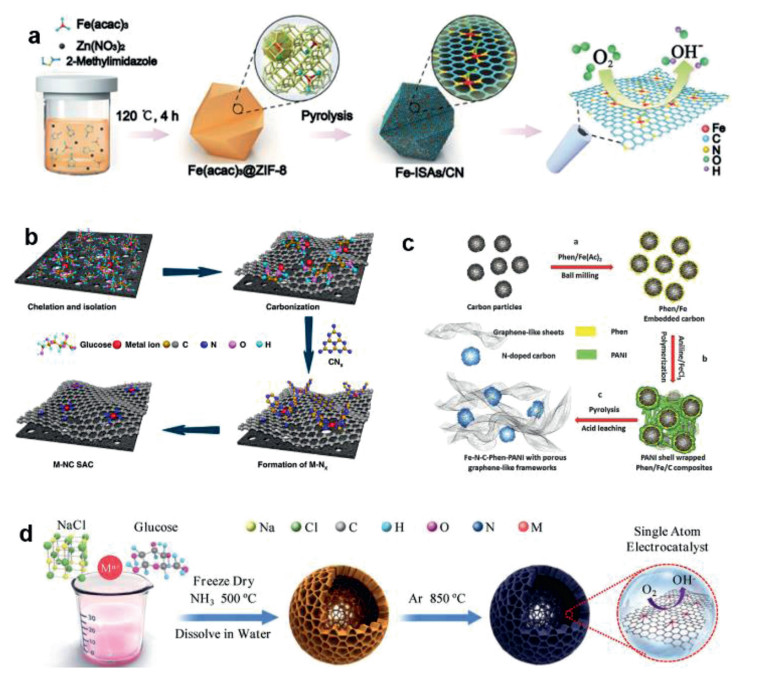
2.1. Pyrolysis 2.1.1. Pyrolysis of MOFsIn recent years, a series of SACs have been fabricated from Metal organic Frameworks (MOFs) materials via pyrolysis routings [19]. The MOFs materials have abundant molecular organic ligand-metal sites, ordered channels and stable chemical frameworks, and can be used as excellent supports for SACs [27-31]. Carbon-based SACs can be prepared by the pyrolysis of bimetal MOFs, in which the agglomeration of active metal sites can be avoided by sacrificing metal compounds such as zinc [42]. The groups of Li developed Co-SACs via direct pyrolysis of Zn/Co bimetallic Zeolitic Imidazolate Frameworks (ZIFs), and the loading of the atomically-dispersed Co can reach up to 4 wt% [28]. They found that Co NPs can be formed by pyrolysis of Zn-free counterpart [43]. In Zn/Co bimetallic ZIF, Co atoms were spatially separated by zinc atoms and 2-methylimidazole, thus effectively enlarging the spatial distances between the Co atoms. The Zn atoms will evaporate during the pyrolysis, leaving the atomically distributed Co atoms on the carbon matrices. Hai et al. fabricated a series of single Co-Nx sites from ZIF-67 via direct pyrolysis [44]. Interestingly, they observed a decreased number of N coordination at higher pyrolysis temperatures (Co-N4 at 800 ℃, Co-N3C1 at 900 ℃, and Co-N2C2 at 1000 ℃), due to the lower thermal stability of N compared to C and the decomposition of N dopants in the carbon lattice. Similar to the Co-SACs, other atomically dispersed metals (e.g., Ni, Fe) can also be fabricated via direct pyrolysis of metal-incorporated ZIF [29, 30, 42, 45]. Chen et al. developed a Fe-N-C catalyst via co-pyrolysis of ZIF-8 and Fe(acac)3, and the derived Fe-Nx sites were uniformly doped in the N-doped porous carbon support (Fig. 1a) [29]. Zhao et al. produced a Ni-N-C catalyst through the pyrolysis of Ni/Zn bimetallic ZIF-8 [30]. Recently, other MOFs materials are also used as the precursors for the synthesis of SACs by direct pyrolysis, such as Ir@ZrO2@C from Ir@UiO-66 [46], Pd1@NC/ZrO2 SACs from PdCl2@UiO-66-NH2 [47], Ru-N-C sites from Ru-incorporated UiO-66-NH2 [48], and CoFe@C SACs from Co/Fe co-incorporated octahedron-shaped triazole-based MOF materials [49].

|
Download:
|
| Fig. 1. (a) Fabricating scheme of the single-atom Fe-Nx-C sites via the pyrolysis of Fe(acac)3 and ZIF-8. Reproduced with permission [29]. Copyright 2017, John Wiley and Sons. (b) SACs prepared using glucose molecules as the precursor. Reproduced with permission [55]. Copyright 2019, Nature Publishing Group. (c) Graphene-like carbon framework confining atomically dispersed Fe sites using phen and polyaniline as precursors. Reproduced with permission [63]. Copyright 2017, John Wiley and Sons. (d) Universal strategy for the fabrication of SACs with glucose and metal precursor. Reproduced with permission [64]. Copyright 2020, John Wiley and Sons. | |
However, the thermal pyrolysis of MOFs would result in the aggregation of metal atoms into atomic clusters or nanoparticles in some cases (probably due to the excessive metal loadings), and an acid washing process would be required to remove the clusters or nanoparticles [49]. Chen et al. derived Mn-N-C SACs from Mn-based MOFs via thermal pyrolysis and subsequent acid etching [50]. The ultrafine MnO nanocrystals were first homogeneously anchored in the porous carbon scaffold after the pyrolysis of Mn-BTC, and the residual Mn species embedded in the carbon matrix mainly exist as SA Mn sites coordinated with O and N atoms. Li et al. equipped Co-N4-C sites in the graphene skeleton through the pyrolysis of Fe-Co-based Prussian blue analogue (PBA) and applied acid washing to remove the metallic FeCo cores Wang and co-workers used carbonization and acid pickling to obtain Fe-SACs from the FePc@ZIF-8 nanocomposites [51]. The FePc molecules (size of 14.6 Å) were first encapsulated into the cavities of ZIF (cavity diameter, 11.6 Å), which burst the ZIF cage and broke the limitation of micro-cavity. The trapped FePc molecules were in-situ transformed into Fe-N sites after pyrolysis treatment. Thereafter, acid treatment was performed to remove the Fe2O3 NPs generated from the aggregation of excessive FePc precursors. Ye et al. also reported the fabrication of ZIF-8 derived SACs with isolated Fe–N sites after thermal pyrolysis and acid pickling [52].
2.1.2. Pyrolysis of small organic moleculesSome transition metal macrocycle substances, e.g., Fe/Co phthalocyanines or porphyrins with natural metal-N coordination, have been used to prepare the corresponding SACs via high-temperature pyrolysis [53]. Zitolo et al. prepared Fe-N-C SACs from Fe(Ⅱ) phthalocyanine, and the Fe-centred moieties in the pyrolysed Fe–N–C materials were identified as the catalytic sites for ORR [53]. Tuo et al. prepared Fe-N/CNTs SACs via pyrolysis at 700 ℃ using Fe porphyrins and aminated carbon nanotubes as the precursors [54]. However, these macrocycle substances are very expensive and some attempts have been made to synthesize the well-defined M-Nx-C using metal salts and N/C-containing small organic molecules such as polyaniline, melamine, imidazole, formamide, pyrrole, and polydopamine [55, 56]. Atomically dispersed Ni sites in C3N4 were prepared using Ni(Ⅱ) chloride and melamine as the precursors [56]. After pyrolysis at 520 ℃, a high loading of confined Ni atoms was reached (10 wt%). Zhao and co-workers prepared a series of SACs (e.g., Fe, Ni, Mn, MO, Cu, Co) by a two-step strategy [55]. These metal ions were first adsorbed onto glucose molecules and then fixed by the oxygen-functionalised groups in porous carbons to achieve the isolation of metal sites (Fig. 1b). The complexes were then mixed with melamine for high-temperature pyrolysis to form M-N-C SACs. Both the chelation of metal ions by glucose and the N complexation by melamine were vital to achieve high loadings of different atomic metals (4.9-12.1 wt%). A recent report has used this method for large-scale synthesis of various SACs [57]. Zhang and co-workers reported a universal ligand-mediated route for the scale-up production of Mn, Fe, Cu, Ru, Cr, Co, Pt, Ni, Zn-based SACs [57]. The complexes of the metal ions and 1, 10-phenanthroline were first fixed onto the commercial carbon black, and then pyrolyzed at 600 ℃. This synthesis method is facile and can produce a variety of high-metal-loading SACs in a kilogram-scale.
In addition to the M-Nx sites, precursors with other heteroatoms (e.g., S, P and B) can also be used to coordinate the metal centres with diverse coordination geometries [58, 59]. Yang et al. fabricated SA Ni coordinated with N and S atoms (A-Ni-NSG) via pyrolysis of melamine, l-cysteine and nickel(Ⅱ) acetate tetrahydrate [58]. Due to the presence of Ni–S/N coordination, the A-Ni-NSG demonstrated faster electron transfer and kinetics compared to the sulphur-free counterpart (A-Ni-NG).
2.1.3. Pyrolysis of polymersThe carbon-based SACs can also be prepared via pyrolysis of the polymers with rich C/N elements [60-63]. For example, the polymerized PDEB (poly(1, 4-diethynyl benzene)) was used as the precursor for preparing SACs with Co-N-C sites via two-step calcination of PDEB, melamine and Co(NO3)2·6H2O [60]. Lou and co-workers developed the Pt-SACs in the porous carbon by using polydopamine/diblock copolymer (PDA/PS-b-PEO) as the precursor [61]. Pt was first loaded onto PDA/PS-b-PEO and then PS-b-PEO was removed during the pyrolysis to form Pt-SACs. Zelenay and co-workers used polyaniline (PANI) and cyanamide (CM) as dual nitrogen precursors to anchor the atomic Fe into the graphitic carbon matrix as Fe-N4 sites via pyrolysis [62]. Chen's group synthesized Fe-N-C-Phen-PANI SACs in graphene-like structures using polyaniline and phenanthroline (phen) as dual nitrogen precursors (Fig. 1c) [63]. Phen not only increased the nitrogen loading in the carbon matrix, but also acts as a sacrificial agent to increase the porosity. The thermal decomposition temperature of phen is low, which is conducive to the formation of a large amount of gases (NH3) during the pyrolysis for N-doping and pore-reforming [63]. Furthermore, a universal synthesis routing of SACs was developed by pyrolyzing the freeze-dried mixture of glucose, metal precursors, and NaCl (Fig. 1d) [64]. During the synthesis process, NaCl particles were coated with a thin layer of glucose, and the metal ions can be anchored on the carbon framework due to the glucose chelation.
In the pyrolysis process, the functional groups in the polymer can also help to fix the extra metal ions and prevent the aggregation of metal ions [65, 66]. Wang et al. reported that the trapping of Co ions by chitosan could in-situ form Co-N4 sites with the addition of NH4Cl [65]. This routing has also been used for various SACs (e.g., Co, Mn, Fe and Ni) fabrication [65, 66].
2.2. Solution-phase synthesisThe single-atom sites can be anchored onto the carbon supports by the routings of solution-phase synthesis via various interactions, including electrostatic attractions, covalent bonding, π–π stacking, and chelating [32-36]. Zhang et al. reported a very simple approach by mixing a H2PtCl6·6H2O solution with hierarchical nitrogen-doped carbon nanocages (hNCNC) suspension [33]. The atomic Pt sites were well-confined in the hNCNC with superior stability, partially due to the synergies of nitrogen dopants and micropores for anchoring, trapping and dispersing the Pt atoms. Hutchings and co-workers developed the Au-doped carbocatalysts (Au/C) via a simple impregnation-adsorption route [34]. The isolated Au(Ⅰ) cationic species in the Au/C catalyst are the analogues of Au(Ⅰ) complexes in the homogeneous Au catalysts, which involved a redox cycle of Au(Ⅰ)/Au(Ⅲ) to catalyze the acetylene hydrochlorination reaction. Bi et al. fabricated the nitrogen-doped graphene with atom-dispersed Ni through a facile ion adsorption procedure [36]. The nickel ions (Ni2+) were coordinated with four pyridinic-N to form the isolated Ni-N4 moieties as catalytic sites in the N-doped graphene (Fig. 2a). Lu and co-workers fabricated the polymerized iron phthalocyanine (p-FePc) from iron phthalocyanine functionalized with four amino groups (NH2-FePc) [67]. The p-FePc was further impregnated onto the CNTs substrates through π-π attractions. The derived FeN4-SAC demonstrated superior performances in ORR and Zn-oxygen battery (Fig. 2b).

|
Download:
|
| Fig. 2. (a) Immobilization of TM ions onto the surface of N-doped graphene through ion adsorption. Reproduced with permission from [36]. Copyright 2018, John Wiley and Sons. (b) In-situ polymerization of NH2-FePc as Fe-N4 sites onto CNTs. Reproduced with permission [67]. Copyright 2020, The Royal Society of Chemistry. (c) Schematic diagram of preparing FeNx/graphene by ball milling process. Reproduced with permission [1]. Copyright 2019, The Royal Society of Chemistry. (d) Proposed mechanism for the preparation of FeNx/graphene via ball milling approach. Reproduced with permission [20]. Copyright 2015, American Association for the Advancement of Science. (e) Schematic diagram of bombardment of high-energy particles. (f) HRTEM image of trapped Pt atom in the bivacancy. (g) Simulated HRTEM image of Fig. 2f. (h) Model for the trapping of Pt atom in the bivacancy. (i) HRTEM image of trapped Pt atom in the trivacancy. (j) Simulated HRTEM image of Fig. 2i. (k) Model for the trapping of Pt atom in the trivacancy. (e-k) Reproduced with permission [72]. Copyright 2012, American Chemical Society. | |
Some metal atoms, e.g., Pt, Ru and Co, can also be fixed onto the g-C3N4 due to the strong coordination between the metal ions and N atoms in C3N4 [68, 69]. In addition to liquid-phase synthesis, g-C3N4-based SACs can also be prepared by direct synthesis approaches [56]. In these methods, carbon and metal sources are mixed by solvents (water, methanol, ethanol, etc.) and heated to dry for homogeneous mixtures. Then SACs were obtained after the pyrolysis of the precursors at 500~600 ℃. Compared with the solution-phase synthesis, solid-phase direct pyrolysis is likely to load more atomic metal sites into g-C3N4. Ohn et al. prepared Ni-based g-C3N4 with a Ni content of 10 wt%. It is noted that further elevating the annealing temperature (> 750 ℃) will transform g-C3N4 into N-doped graphene with well-dispersed SA metal sites [70].
2.3. Ball millingSome SACs have been prepared on the basis of ball milling routing. This is because the ball milling process can produce strong shear forces and local temperatures up to 1000 ℃, which will re-establish the chemical bonds of the organic molecules and form the ideal coordination structure of the single metal atom sites [38]. As shown in Figs. 2c and d, Deng and co-workers fabricated the Fe-N4/graphene by the ball milling [20, 37, 38]. The graphene was first exfoliated from the natural graphite powder by ball milling under Ar atmosphere [20, 38]. Then, Fe phthalocyanines (FePc) was mixed with the prefabricated graphene flakes and underwent further ball milling for a period of time. Then Fe atoms were well incorporated into the graphene matrixes coordinated with four N atoms, with Fe loading of 2.7 wt% [38]. However, further increasing Fe loading led to metal agglomeration, forming NPs or clusters.
2.4. Electron/ion irradiationRecent studies found that some metal atoms (e.g., Pt, In and Fe) can be captured by the graphene vacancies, which were created via electron/ion irradiation [71, 72]. Warner and co-workers observed the trap of Fe atoms within the graphene vacancies created by focused electron beam irradiation at 80 kV [71]. Once the iron atoms are embedded into graphene, they can be refabricated via binding with three or four neighboring carbons [71]. Zhang and co-workers developed a two-step process for the fabrication of graphene-based SACs [72]. The vacancies were first created by the strong bombard of energetic particles and then different single atom metals (Pt, Co, and Ir) were filled into these vacancies (Fig. 2e). High Resolution Transmission Electron Microscope (HRTEM) images of the doped Pt atoms in bivacancy and trivacancy as well as their atomic models are shown in Figs. 2f-k. The migration barrier of Pt atoms was calculated to be between 0.2 V and 0.8 eV, ensuring the high mobility even at room temperature. However, the yield of SACs prepared by this method is too low, so it is of scientific value only in the study of catalytic mechanism.
2.5. Physical and chemical depositionFabrication of SACs can also be achieved by deposition of single metal atoms onto a select carbon matrix via chemical vapor deposition (CVD) [39-41], atomic layer deposition (ALD) [73], and electrochemical deposition [40, 73]. As for the CVD, the metal film or foil (e.g., Cu and Ni) can be both used as a substrate and catalyst for the growth of graphitic carbons by interacting with the gaseous organic molecules during pyrolysis [39]. Chen and co-workers fabricated the nanoporous graphene with atomically deposited Ni through a CVD process [39]. Nanoporous Ni was first prepared via dealloying Ni30Mn70 sheets, and the nanoporous Ni/graphene composites were formed after the CVD process using benzene as the carbon source. Nanoporous graphene with single-atom Ni was then formed after acid etching of nano-porous Ni foam in a HCl solution. Graphene vacancies formed during the CVD process, which enabled the chemical bonding of Ni–C and determined the catalytic activity of isolated single-atom Ni sites. The group of Qiu also fabricated Mo single atoms/clusters on nanoporous holey graphene using the CVD technique. NiMoO4 nanofiber and SiO2 NPs were used as the CVD templates for the graphene/porous NiMo hybrids (Fig. 3a). Mo-doped holey porous graphene was then obtained after HNO3 pickling to remove the SiO2 template [41, 74].

|
Download:
|
| Fig. 3. (a) STEM image of the as-prepared Ni-SAC. (b) AC HADDF-STEM image of Ni-SAC. (c) High resolution bright-field STEM image of Ni-SAC. The defective sites (vacancy with single-atom Ni trapped and vacancy without single-atom Ni trapped) are pointed with red arrows. (d) Corresponding HADDF-STEM image of Ni-SAC of Fig. 3c. The Zoomed-in image of vacancy (e) with single Ni atom trapped, and (f) without single Ni atom trapped. Reproduced with permission [79]. Copyright 2018, Elsevier. | |
ALD is a vapor deposition technique, which can control the amounts of deposited materials. As a result, this technique has been widely used in the synthesis of nanomaterials ranging from NPs, nanoclusters to single atoms. In one study, Lu and co-workers realized the precise synthesis of Pt dimers through two cycles of Pt ALD on the graphene as Pt-O2-Pt sites (Fig. 3b) [75]. However, two major challenges of ALD technique for fabricating SACs are the low metal loadings and nonuniform of single metal sites anchored on carbon matrixes. In addition, fabricating the SACs with high metal loadings via ALD technique will inevitably result in the aggregation of metal atoms into nanoclusters or NPs [76].
Electrochemical deposition has also used for the single Pt atom catalysts [77]. Tavakkoli and co-workers proposed a facile electrochemical method to disperse the Pt on the single-walled carbon nanotubes [77]. Pt ions were gradually dissolved in sulphuric acid from a Pt plate and then electrochemically deposited on the carbon nanotubes (Fig. 3c). In another study [78], Pt single atoms were deposited on CoP-loaded nanotubes via the potential-cycling routing. Although electrochemical deposition has not been widely used in the preparation of SACs, it is worthy of foundational research.
3. Characterizations of SACsAfter the synthesis of SACs, it is of great significance to identify the structural features of SACs and distinguish them from nano-metal catalysts. As a result, the atomic dispersion and the configuration of single-atom sites should be determined. Several new characterization techniques, e.g., scanning tunnelling microscopy (STM), spherical aberration-corrected transmission electron microscopy (AC HAADF-STEM), and X-ray absorption spectroscopy (XAS), have been applied to reveal the properties of SACs [19-24].
3.1. HAADF-STEMTo "visualize" the morphology of single-atom catalysts, the resolutions of conventional SEM or TEM technique are not enough, while some advanced techniques, such as spherical aberration-corrected transmission electron microscopy (AC HAADF-STEM), can promote our morphological to detect individual dopants in the SACs. For example, Zhang et al. developed a Ni-SAC by dispersing the single-atom Ni sites on the defective graphene (denoted as A-Ni@DG); the SA Ni sites were detected through a variety of microscopic techniques [79]. A HRTEM image of the A-Ni@DG showed a much more fragmentized and porous nanostructure. No NPs or single atoms were observed (Fig. 3a). In contrast, AC HAADF-STEM clearly illustrated the presence of abundant bright dots in the as-prepared Ni-SAC with an average dot size of ~0.24 nm (Fig. 3b). The Energy dispersive spectroscopy (EDS) mappings (inset in Fig. 3b) confirmed that these bright dots were single Ni atoms. The bright-field HRTEM image (Fig. 3c) showed the existence of crests and sags in the grid of A-Ni@DG, which are attributed to the defective sites based on the corresponding HADDF-STEM image (Fig. 3d). The crests and sags can be ascribed to the di-vacancy trapped with single atom Ni (Fig. 3e) and the pure di-vacancy (Fig. 3f), respectively.
Recent studies also reported that the AC HAADF-STEM technique can further provide some deeper information on the molecular features of the single-atom sites, e.g., the atom distance and coordination structures [80, 81]. Several Fe-NxCy SAs/N-C catalysts with a variety of Fe-N configurations (Fe-N4, Fe-N3C1 and Fe-N2C2) have been developed by Pan et al. [80]. The finely dispersed bright dots corresponding to the single atoms can be visualized from the AC HAADF-STEM images (Figs. 4a–c). The EDS mappings (Fig. 4d) showed that the Fe, N, and C elements were uniformly distributed in the framework of as-prepared catalysts. The bond lengths of Fe-C and Fe-N are different, and Fe-N bond (1.92~1.95 Å) is slightly longer than Fe-C bond (1.87~1.90 Å); thus, the bond length can be leveraged to distinguish between the two coordination structures [80]. The distances between the two neighboring Fe atoms are approximately 4.5 Å for Fe-N4 sites and 3.5 Å for Fe-N2C2 sites. This phenomenon was consistent with the theoretical results, which further confirmed the existence of Fe-C coordination in the Fe-N2C2 sites. Chen et al. also observed that the brightness of Ag atoms can be easily distinguished from other atoms, and the densely arranged bright dots in the HAADF-STEM image of Ag-SAC were Ag atoms (Fig. 4e) [81]. The closest distance (5.7 Å) between two the adjacent Ag atoms was significantly longer than that of the metallic Ag-Ag bonds (2.89 Å), indicating the isolated state of Ag atoms (Fig. 4f).

|
Download:
|
| Fig. 4. AC HAADF-STEM images of (a) Fe-N4, (b) Fe-N3C1, (c) FeN2C2 sites in different Fe-NxCy SAs/N-C catalysts. Insets are the corresponding configuration models. Green, yellow, red and balls represent the atoms of Fe, C and N, respectively. (d) EDS mappings of Fe-N4 SAs/N-C. (a-d) Reproduced with permission [80]. Copyright 2019, Nature Publishing Group. (e) AC HAADF-STEM image of the Ag-SAC. (f) Three-dimensional projected image of a dash rectangle in the panel for Fig. 4e. (e, f) Reproduced with permission [81]. Copyright 2015, John Wiley and Sons. | |
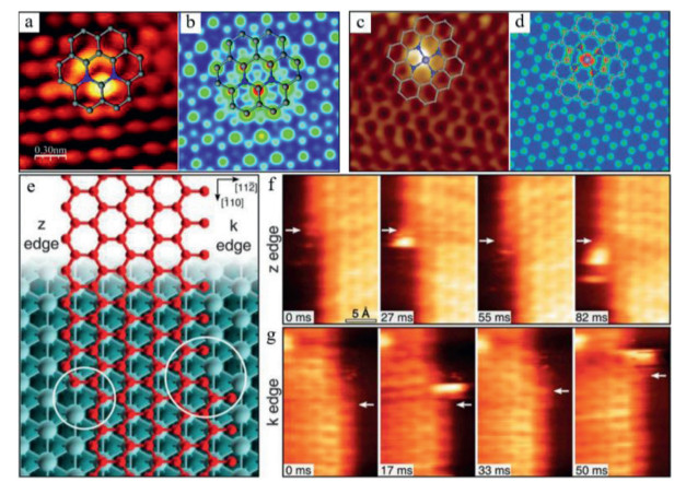
STM is also a useful analytical method to directly reveal the electronic characteristics of SACs and indirectly distinguish the elements with similar atomic numbers [82]. Deng et al. reported the fine triangular mesh structure of N-doped graphene with a lattice constant of 2.4 ± 0.1 Å in the STM images [83]. More importantly, they first observed the isolated N dopants in the graphene lattice based on the STM technique (Fig. 5a). The STM simulation (Fig. 5b) showed that the bright spots were the C atoms in adjacent to the N atoms, indicating that the density of electronic state of carbons increased near the Fermi level due to the doping of N atoms. Recently, the same group also employed the low-temperature STM characterization to reveal the configuration of Fe-N4 sites in graphene [20, 84]. The bright dot in the STM image of Fe-N4 (Fig. 5c) was assigned to the solely dispersed iron atom. The brightness of the surrounding C or N atoms is also significantly higher than that of other C atoms, indicating that SA Fe has a very significant impact on the electronic state of its neighboring C and N atoms. The DFT-simulated STM image in Fig. 5d confirmed the observed Fe-N4 structures. Furthermore, the catalytic behavior of Ni atoms at the graphene edges can be directly observed by the high speed STM techniques as shown in Figs. 5e-g [85].

|
Download:
|
| Fig. 5. (a) STM image and structural analysis of N-doped graphene. (b) Simulated STM of N-doped graphene. Reproduced with permission [83]. Copyright 2011, American Chemical Society. (c) STM image and structural analysis of FeN4/graphene. (d) Simulated STM image of FeN4/graphene. Reproduced with permission [20]. Copyright 2015, American Association for the Advancement of Science. (e) The k and z edges of an epitaxial graphene layer on Ni (111). High-speed STM sequence in quasi-constant height mode at (f) z, and (g) k edges. Reproduced with permission [85]. Copyright 2018, American Association for the Advancement of Science. | |
X-ray absorption spectroscopy (XAS) can evaluate the local chemical structures of SACs by measuring the transitions of metals from the core electronic state to the excited state and continuum. When the spectral region is extended to 30-50 or 50-1000 eV, XAS can be divided into X-ray absorption near-edge structure (XANES) and extended X-ray absorption fine structure (EXAFS). The EXAFS can be used to probe the bonding environment of SACs and provide the essential information such as coordination number, and bond length [23, 24]. Different coordination environments of Co-Nx-C sites prepared after pyrolyzing the Zo-ZIFs at different temperatures (700, 800 and 900 ℃) were verified by Fourier transform (FT)-EXAFS [28]. The Co-N coordination numbers for the three samples were calculated to be 2.2, 3.1 and 4.1 based on the EXAFS fitting, which were designated as Co-N2, Co-N3 and Co-N4, respectively (Fig. 6a). All the three samples with atomically dispersed Co-Nx sites exhibited a prominent peak at 1.4 Å, and no metallic Co-Co bond (2.2 Å) was detected. Most interestingly, the peak intensity of the Co-N coordination reduced as the coordination numbers of Co-N decreased from 4 to 2, implying the decreased number of N coordination around the Co centre.

|
Download:
|
| Fig. 6. (a) Comparison of FT-EXAFS spectra of Co-N4, Co-N3, and Co-N2 configurations. Reproduced with permission [28]. Copyright 2018, John Wiley and Sons. (b) FT-EXAFS spectra of Co-N5/HNPCSs, CoO, Co3O4, CoPc and Co foil at R space. (c) Configuration model of Co-N5, the wathet, blue, gray and white represent the atoms of Co, N, C and H, respectively. (d) WT-EXAFS spectra of Co-N5/HNPCSs, and other samples. (e) FT-XANES spectra of Co-N5/HNPCSs, and other samples. (b-e) Reproduced with permission [86]. Copyright 2018, American Chemical Society. (f) FT-XANES spectra of Co-N4, Co-N3, and Co-N2 configurations. Reproduced with permission [28]. Copyright 2018, John Wiley and Sons. (g) FT-XANES spectra of Fe–NC SAC, FePc, and Fe foil (inset: first-derivative curves). Reproduced with permission [55]. Copyright 2019, Nature Publishing Group. | |
The wavelet transform (WT) of EXAFS allows the resolution of backscattered atoms with the information of elemental nature and radius distance. Li and co-workers developed the atomically-dispersed Co-Nx sites in N-doped porous and hollow carbon-spheres (Co-Nx/HNPCSs) [86]. The FT-EXAFS spectrum of the as-prepared Co-Nx/HNPCSs featured a peak at 1.5 Å (Fig. 6b), which was assigned to the Co-N coordination. The coordination number of Co-Nx was 5 according to the EXAFS fitting and the atomic structure of Co-N5 was shown in Fig. 6c. However, the peak was indistinguishable for the FT-EXAFS spectrum of CoPc. The WT-EXAFS spectra showed the maximum intensity at 5 Å−1 (Fig. 6d), which corresponded to the Co-N bond by comparing with the benchmark samples of Co foil, CoO, Co3O4 and CoPc [86]. In addition, a well-resolved difference of WT maximum between CoPc and Co-N5/HNPCSs was observed, which were associated with Co-C and Co-N coordination, respectively. Thus, the detailed information on the coordination environment of the single-atom can be obtained by combining the WT and FT-EXAFS analysis.
Based on the XANES result, the chemical state and geometric information of the single-atom sites can be accurately determined. For example, Li et al. developed a Co-N5-C catalyst with similar coordination structures to CoPc [86]. The XANES spectra of CoO, Co3O4, CoPc and Co-N5-C indicated that the absorption edge position of the Co-N5 sites was located between Co3O4 and CoO (Fig. 6e), which suggested that the valence state of single-atom Co in the Co-N5-C catalyst was between +2 and +3 [86]. The evolution of valence states in different Co-Nx configurations (e.g., Co-N4, Co-N3 and Co-N2) was detected by XANES (Fig. 6f). A significant shift to the lower energy of pre-edge centroid was observed between the Co-N4 and Co-N2, which indicated the decreased oxidation state of Co [28]. Zhao et al. reported a slight difference in the XANES spectra of the non-pyrolyzed FePc and pyrolyzed Fe-SAC with well-defined Fe–N4 coordination (Fig. 6g) [55]. The pre-edge feature at 7118 eV reveals a strong intensity for FePc with a square-planar configuration. However, such a peak disappeared in the pyrolyzed Fe-SAC, which indicated a distorted D4h symmetry with axial ligands. XANES analysis can be further combined with theoretical calculations to simulate a wide range of well-defined model structures [80]. Pan et al. calculated the XANES models of Fe-N4, Fe-N3C, and FeN2C2 moieties in SACs [80] The results showed that the calculated spectra of FeN2C2, Fe-N3C1 and Fe-N4 had the similar characteristics to the experimental spectra, especially the shape and position of peaks around 7118 eV, which further demonstrated the well-defined structures of the FeN4, Fe-N3C1, and Fe-N2C2 sites in SACs.
3.4. XPSThe elemental compositions of SACs as well as valence states of specified elements can be determined by the XPS measurement [87, 88]. Although the atomic ratios of single metal atom are very low, XPS can provide some specifical information on the chemical states of nitrogen in metal-Nx sites of SACs. Zhao et al. used XPS to analyze the atomic Fe-N sites (Fe–NC SACs) confined in N-rich carbons [55]. The N 1s spectrum of Fe–NC SACs can be deconvoluted into several individual peaks, corresponding to the fractions of graphitic-N, pyridinic-N, Fe–Nx, pyrrolic-N, and oxidized-N. The observed Fe–Nx peak in Fe–NC SACs (399.5 eV) was analogous to the Fe–Nx counterpart in FePc. The Fe 2p XPS spectrum indicates that the Fe species in Fe–NC SACs mainly exist as Fe(Ⅱ). As a result, the XPS results provided an evidence for the Fe–Nx coordination in Fe–NC SACs.
In many cases, XPS technique can also help to distinguish the structural differences between SACs and their NPs counterparts [88]. Yin and co-workers compared the N 1s and Co 2p spectra of Co-SAs/N-C catalyst and NPs counterpart (Co-NPs/N-C). Compared with Co-NPs/N-C, the strongest pyridine N peak in Co-SAs/N-C showed ~0.3 eV of bond energy shift. The Co-SAs/N-C also showed the distinct up-shifting (1.9-2.3 eV) in the Co 2p1/2 and Co 2p2/3 peaks compared to Co-NPs/N-C. The peak of Co 2p2/3 for the Co-SAs/N-C was centred between Co0 and Co2+, which is the characteristic of ionic Coδ (0 < δ < 2). Therefore, Co atoms are dominantly coordinated with pyridine N to form the Co-Nx structures. Similar bond energy shift of pyridine N peaks after bonding with single atom metals was observed for the confined Ni-Nx sites in nitrogenated graphene [58], activated carbon supported SA Fe [89], and similar structured carbon-based SACs [19, 86, 90, 91].
3.5. Mössbauer spectroscopyMössbauer spectroscopy can distinguish a variety of iron-based SACs with similar structures but different spin and oxidation states. For example, the Mössbauer spectra of atomic Fe-Nx embedded g-C3N4 are fitted with three doublets (D1-D3). The doublet D1 with smaller isomer displacement corresponded to Fe(Ⅲ), while the two quadrupole-splitting doublets (D2, D3) were assigned to the high-spin Fe(Ⅱ). High spin Fe(Ⅱ) quaternary division values indicated a different coordination environment, which was expected as the Fe-Nx species [92]. Similar Mössbauer results were also reported by different groups to identify the changes of Fe species in various Fe-N4 SACs before and after benzene oxidation [20, 80]. The Fe-N4 sites were determined from the Mössbauer spectrum of FeN4/GN, while the population of symmetrical O=Fe=O structures were significantly increased after H2O2 treatment. These O=Fe=O structures gradually disappeared during benzene oxidation, confirming that the Fe-N4 moieties were the intrinsic active sites for the catalytic process.
4. DFT calculation 4.1. Electronic structures/spin of SACsThe catalytic activities of SACs are close related to their electronic features and geometric configurations. As a result, many qualitative and quantitative information of SACs (e.g., D band structure, charge/spin density, energy band and density of states (DOS) can be analyzed by DFT calculation [93].
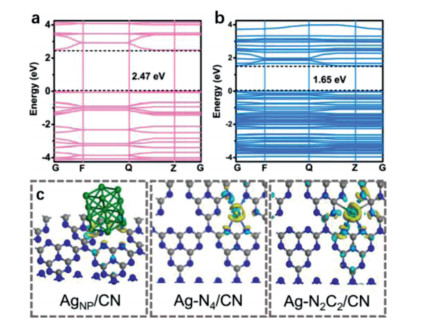
The electronic structures and reactivity of SACs were quite different from their clusters, NPs and bulky counterparts. For example, single-atom Ag confined in carbon nitride (Ag-N2C2/CN, and Ag-N4/CN) exhibited much higher performances in photocatalytic hydrogen evolution than the silver NPs catalyst (AgNP/CN) [94]. The electronic structure of Ag-N2C2/CN implies the significant expansion of light absorption range of carbon nitride after the introduction of Ag single atoms, thus obtaining a superior photocatalytic activity than the bare carbon nitride (Figs. 7a and b). The charge densities of Ag-N2C2/CN, Ag-N4/CN and AgNP/CN are significantly different, and Ag-N2C2/CN was more favorable for charge re-distribution, resulting in a greater electron transfer from carbon nitride to single atom Ag to form low-valence Ag sites (Fig. 7c).

|
Download:
|
| Fig. 7. Band structures of (a) CN and (b) Ag-N2C2/CN. (c) Charge density differences of AgNP/CN, Ag-N2C2/CN and Ag-N4/CN. Reproduced with permission [94]. Copyright 2020, John Wiley and Sons. | |
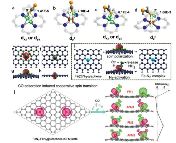
The spin state can be used to described the spin potential configuration of the d electrons of the metal atom, which represents an essential electronic feature of SACs. Different spin states usually have different energies and may result in different reaction barriers [25, 26]. Hong et al. reported that C2N–Co(Ⅱ) in a low spin state is favorable for HCOOH dehydrogenation because of the greatly decreased energy barrier of the rate-determining step [25]. This is mainly because of the strong charge extraction from HCOOH and C2N to the single metal sites. Gong et al. reported that the spin-state transition of SA Co in different oxidation states remarkably affected the activity and selectivity on CO2 adsorption and activation on COF-367-Co [26]. DFT calculation indicated that the oxidation states of Co (Co(Ⅱ) and Co(Ⅲ)) remarkably affect the spin state for the interaction with CO2 and the intermediate (HCOOH). The coupling model of CO2-adsorbed Co(Ⅱ) sites was based on the Co-3dxz or Co-3dyz coupling with O-2p, which was different from Co-3dz2 coupling with O-2p in CO2-adsorbed Co(Ⅲ) sites (Figs. 8a-d). This noble distinctions accounted for the stronger CO2 interacting with Co(Ⅲ) sites in reference to the CO2-adsorbed Co(Ⅱ) sites. Similarly, the interactions of HCOOH with Co(Ⅲ) sites was stronger than that with Co(Ⅱ) sites. As a result, the Co(Ⅲ) sites were preferable to the adsorption of CO2 and HCOOH, which clearly evidenced the different catalytic performances over the Co(Ⅱ) sites.

|
Download:
|
| Fig. 8. Coupling modes of CO2 and HCOOH adsorbed onto CoII or CoIII sites in COF-367-Co at different spin states (a) CO2-adsorbed CoII site, (b) CO2-adsorbed CoIII site, (c) HCOOH-adsorbed CoII site, and (d) HCOOH-adsorbed CoIII site. (a-d) Reproduced with permission [26]. Copyright 2020, American Chemical Society. Isosurface of the spin-resolved density of FeN3-graphene in (e) top and (g) side views. Isosurface of FeN4-graphene in (f) top and (h) side views. (i) Mechanism of nitrogen fixation by FeN3-embedded graphene. (e-i) Reproduced with permission [95]. Copyright 2016, American Chemical Society. (j) Co adsorption induced cooperative spin transition of two nearby Fe sites embedded at graphene. Reproduced with permission [97]. Copyright 2018, American Chemical Society. | |
Governing the coordination environment of single metal centres with the carbon matrixes can change the spin configuration and fine-tune the catalytic reactivity/selectivity in targeted reactions. Li et al. reported that the FeN3 sites in graphene was conductive to adsorbing N2 and catalyzing the conversion of dinitrogen to ammonia, while the FeN4 configuration was not favorable for N2 capture [95]. The top and side views of spin resolution density showed that FeN3/graphene has a C3v symmetric non-plane geometry and Fe atoms located outside the graphene plane. The charge cloud was mainly distributed near the Fe atom, indicating that its spin moment mainly stemmed from the Fe centre (Figs. 8e-h). As for FeN4/graphene, the isolated Fe atom was completely doped into the graphene lattice and the spin moment (2.00 µB) was smaller than that of the FeN3 sites (3.16 µB). The spin moment of SACs has been proved to be vital in N2 adsorption and subsequent activation. Compared with FeN4, FeN3 showed a rather larger and more centralized spin moment with bulged Fe atom exposed above the graphene layer, which could promote N2 adsorption and activation of the inert N-N triple bond. In addition, the catalytic conversion of the activated N2 into NH3 can be facilitated by the synergy between FeN3 and graphene with a highly conjugated π system and locally enriched protons (Fig. 8i). Similarly, Guo et al. found that the exchange splitting degree of spin state of iron sites intensified with the increased Fe-N coordination number [96].
The interplay between single-atom metal sites and carbon matrixes will cause mutual effects on their respective geometric interactions and spin configuration. Additionally, recent research indicates that the cooperative spin transitions between the adjacent metal atoms can also affect the spin configurations and thus the catalytic activity of each SA sites [97, 98]. Jiang and co-workers found a synergistic interaction between the two adjacent Fe sites dispersed in N-doped GO with the aid of CO adsorption [97]. The two cooperative Fe atoms responded to the CO molecules by communicating structural adaptations and electronic transformations. The adsorbed CO not only changed the spin culture of the adsorbed SA-Fe, but also altered the spin of the adjacent Fe sites. Thus, the two nearby SA-Fe sites showed unique oscillatory spin coupling (Fig. 8j). This theoretical investigation indicated the existence of cooperative communications between adjacent two single-atom metal sites, and it is also nontrivial to the spin configurations. Han et al. also reported such synergistic effects of two adjacent Fe-N-C sites on ORR over monodispersed Fe-N-C catalysts [98]. In comparison, the neighboring effect on ORR was significantly weaker for FeN4, except in the case of the two extremely close FeN4–FeN4 sites (4.1 Å). The difference in neighboring effects between FeN4 and FeN3 was partially due to the greater magnetic exchange interaction of FeN4 than FeN3, resulting in stronger inter-site communication.
4.2. Intrinsic active sites and reaction pathwaysIt is of great significance to unravel the active sites of SACs and the catalytic mechanism in the targeted reaction via DFT calculation [93, 99]. For example. by analyzing the DOS at the Fermi level, one can identify the specific atoms that make contributions to the states, which play a significant role in determining the chemical reaction dynamics [100]. Jiang et al. found that the isolated nickel atoms (e.g., Ni-N-C) in graphene were favorable to reduce CO2 to CO with a high CO selectivity (> 90%) [100]. Theoretical simulations indicated that when atomically-dispersed Ni sites were coordinated onto the graphene surface, a much higher DOS around Fermi energy than that of Ni(111) was observed. The optimized electronic structure of Ni-SACs could greatly promote the transformation of CO2 to CO and effectively inhibited other competing reactions. A simple thermochemical analysis shows that CO2 was reduced through two steps to generate the intermediates of *COOH and *CO successively (Fig. S1a in Supporting information). Graphene nanosheets with single cobalt sites (CoN4/GN) are used as a stable and highly active counterelectrode for the interconversion of the redox couple of I−/I3− [37]. DFT calculation showed that the excellent catalytic activity of the CoN4/GN catalyst was due to the optimal binding energy of iodine onto the single-atom Co, giving rise to a dynamic balance of the adsorption and desorption process (Fig. S1b in Supporting information). Furthermore, the CoN4 moiety is the most stable configuration among a variety of MN4 moieties because of the optimal Co–N bond energy (Figs. S1c-e in Supporting information).
The electronic characteristics of the SACs are close related to their coordination environments, which would determine the forms of intermediates and catalytic pathways [6, 80]. Pan et al. regulated the coordination structures of SA Fe-NxCy (Fe-N4, Fe-N3C1, Fe-N2C2) catalysts for the benzene oxidation [80]. The catalytic activity of single-atom Fe decreased as the one or two coordinated N atoms were replaced by the C atoms (Fig. S1f in Supporting information), indicating that the benzene oxidation reaction (BOR) activities of central Fe sites are sensitive to the change of coordination environment. In addition, the O=Fe=O/Fe=O species were formed at the Fe-NxCy centres during BOR. The charge density differences of O=Fe=O/Fe=O suggested that significant charge transfer occurred between Fe-N4 and O, which facilitated C–H bond activation. As a result, the coordination structures not only changed the electronic characteristics of SACs, but also determined the formation of relevant key reactive species and the pathways of benzene oxidation. To further evaluate the impacts of electronic environments on the activity of SACs, Qiao's groups constructed a full profile of 20 types transition metals-based SACs for electrocatalytic nitrogen reduction reaction (ENRR) via DFT simulations [101]. Three kinds of nitrogen-doped carbon (NC) substrates, including g-C3N4 and graphene doped with three (N3) and four (N4) nitrogen atoms, were used as the carbon hosts. Contour plots of the limiting potential based on the ΔG(NNH*) and ΔG(NH2*) indicated that the changes in the electronic characteristics of SACs were controlled by coordination environment which controlled the ENRR activity (Fig. S1g in Supporting information). In addition, Fig. S1h (Supporting information) illustrates that the NC substrate with N4 is the most stable configuration with a decomposition potential of −1.03 V vs. SHE, as compared to NC with N3 (−0.71 V vs. SHE) and g-C3N4 (−0.81 V vs. SHE). Therefore, in order to ensure the stability of the carrier and to avoid the risk of fouling caused by the decomposition of carbon carriers, a higher ENRR limiting potential which would not cause substrate corrosion was essential for the selection of ideal ENRR electrocatalyst. As for g-C3N4-based SACs, only several transition metals (Ru, Mo, Rh, Co, V, Tc, Nb and W) were stable in ENRR. This is because that their negative ENRR limit potentials are smaller than the potential of substrate decomposition.
In addition, the energy profiles can also be determined via DFT calculation to elucidate the catalytic pathways/mechanisms of SACs in targeted reactions [86]. Pan et al. developed a single-atom Co-N5 catalyst for the reduction of CO2 with extremely high CO selectivity. The CO2 reduction pathway over the CO-N5 site was studied through computational hydrogen electrode model and optimized configurations of key intermediates, e.g., CO* and COOH*. The calculated free energy of CO2 reduction indicated that the Co-N5 sites were the active centres coordinating the COOH* formation and CO desorption. Deng et al. reported that the single-atom Fe-N4 sites exhibit superior catalytic performances for benzene oxidation to phenol [20]. The free energy profiles and reaction pathways of benzene oxidation over the confined iron sites were computed. The H2O2 molecule was easily dissociated over the well-dispersed Fe sites by forming an Fe=O intermediate, which was the key step to promote the oxidation of benzene to phenol. Zhang and colleagues fabricated a carbon-based SAC with Ni-N5 sites for hydrogenation and cellulose valorization [102]. DFT calculations show that meta-stable Hδ-N and Hδ-Ni configurations were formed after the activation of H2 molecules. The localized molecular orbitals and localized orbital bonding analysis of the two configurations showed the oxidation states of the Ni centre and each split H atoms. This heterolytic dissociation mode was similar to the frustrated Lewis pair in the homogeneous system for effectively heterolytic activation of dihydrogen [102]. As a result, a series of hydrogenation reactions were catalyzed by the well-defined Ni-N5 sites in Ni-SACs.
5. Conclusions and perspectivesSingle-atoms anchored carbon-based materials are a new type of high-efficiency catalysts for multiple reactions. In this review, we started with the fabrication strategies (e.g., pyrolysis, solution-phase synthesis, electron/ion irradiation, Ball milling, physical and chemical deposition) for carbon-based SACs. Subsequently, multiple characterization methods specific to SACs are highlighted. We also showcased the electronic structures/spin of SACs, as well as their intrinsic active sites and reaction pathways. In this way, we can understand the synthesis mechanism of different single-atom sites formed in SACs, determine their distinct different geometric and electronic features, and ultimately understand the structure-catalysis of SACs at the atomic scale. In addition, the catalytic single-atom sites play an important role in regulating the reaction kinetics and catalytic activity, which make it possible to differentiate SACs from traditional NPs catalysts in terms of new reaction pathways and electron transfer kinetics.
Despite the progress, challenges remain. At present, single atoms can be "visualized" by HADDF-STEM technique and their coordination structures can be identified by XAS analysis. However, there is still a lack of a powerful characterization technique that can directly probe the coordination structures and electronic features of single-atom sites in SACs. On the other hand, the identification of the active sites of SACs and the determination of the structure-property relationship are closely related to the development of advanced experimental characterizations and computational achievements. Apart from the characterization techniques and DFT calculations, machine learning (WL) can directly predict the high-throughput catalytic performances to accelerate on-demand screening and discovery of SACs. It can also provide new insights for us to understand the kinetics of SACs in different catalytic systems from the molecular level to the macro level. In addition, the single atomic catalytic sites may change under the actual catalytic conditions, which makes it difficult to identify the actual active sites and analyze the reaction mechanism. So far, there are few studies on the evolution of single-atom sites under operating conditions.
Declaration of competing interestThe authors declare that they have no known competing financial interests or personal relationships that could have appeared to influence the work reported in this paper.
AcknowledgmentsThe research work was supported by Tai Shan Scholar Foundation (No. ts201511003). The authors also want to thank Conghua Qi from Shiyanjia Lab (www.shiyanjia.com). In addition, X. Duan acknowledges the financial support from the Australian Research Council via Discovery Projects (Nos. DE210100253 and DP190103548).
Supplementary materialsSupplementary material associated with this article can be found, in the online version, at doi: 10.1016/j.cclet.2021.07.050.
| [1] |
H.L. Fei, J.C. Dong, D.L. Chen, et al., Chem. Soc. Rev. 48 (2019) 5207-5241. DOI:10.1039/c9cs00422j |
| [2] |
Y.N. Shang, X. Xu, B.Y. Gao, S.B. Wang, X.G. Duan, Chem. Soc. Rev. 50 (2021) 5281-5322. DOI:10.1039/d0cs01032d |
| [3] |
M.A. Oturan, J.J. Aaron, Crit. Rev. Environ. Sci. Technol. 44 (2014) 2577-2641. DOI:10.1080/10643389.2013.829765 |
| [4] |
L. Jiao, H. Jiang, Chem 5 (2019) 786-804. DOI:10.1016/j.chempr.2018.12.011 |
| [5] |
Y.N. Shang, X. Xu, Q.Y. Yue, B.Y. Gao, Y.W. Wei, Environ. Sci. Nano 7 (2020) 1444-1453. DOI:10.1039/D0EN00050G |
| [6] |
X. Li, L. Liu, X. Ren, et al., Sci. Adv. 6 (2020) eabb6833. DOI:10.1126/sciadv.abb6833 |
| [7] |
L. Chen, C. He, R. Wang, et al., Chin. Chem. Lett. 32 (2021) 53-56. DOI:10.1016/j.cclet.2020.11.013 |
| [8] |
L. Chen, X. Xu, W. Yang, J. Jia, Chin. Chem. Lett. 31 (2020) 626-634. DOI:10.1016/j.cclet.2019.08.008 |
| [9] |
L. Fu, R. Wang, C.X. Zhao, et al., Chem. Eng. J. 414 (2021) 128857. DOI:10.1016/j.cej.2021.128857 |
| [10] |
J. Pan, B. Gao, P. Duan, et al., J. Mater. Chem. A 9 (2021) 11604-11613. DOI:10.1039/d1ta02237g |
| [11] |
J. Li, Y. Zhou, W. Tang, et al., Appl. Catal. B: Environ. 285 (2021) 119861. DOI:10.1016/j.apcatb.2020.119861 |
| [12] |
X. Cui, W. Li, P. Ryabchuk, K. Junge, M. Beller, Nat. Catal. 1 (2018) 385-397. DOI:10.1038/s41929-018-0090-9 |
| [13] |
R. Wang, C.Z. He, W.X. Chen, et al., Chin. Chem. Lett. (2021). DOI:10.1016/j.cclet.2021.05.024 |
| [14] |
C. Chen, T. Ma, Y. Shang, et al., Appl. Catal. B Environ. 250 (2019) 382-395. DOI:10.1016/j.apcatb.2019.03.048 |
| [15] |
Y. Qi, J. Li, Y. Zhang, et al., Appl. Catal. B Environ. 286 (2021) 119910. DOI:10.1016/j.apcatb.2021.119910 |
| [16] |
C.Z. Wan, X.F. Duan, Y. Huang, Adv. Energy Mater. 10 (2020) 1903815. DOI:10.1002/aenm.201903815 |
| [17] |
B.K. Huang, Z.L. Wu, H.Y. Zhou, et al., J. Hazard. Mater. 412 (2021) 125253. DOI:10.1016/j.jhazmat.2021.125253 |
| [18] |
Y.B. Lu, Z.H. Zhang, H.M. Wang, Y. Wang, Appl. Catal. B: Environ. 292 (2021) 120162. |
| [19] |
X.N. Li, X. Huang, S.B. Xi, et al., J. Am. Chem. Soc. 140 (2018) 12469-12475. DOI:10.1021/jacs.8b05992 |
| [20] |
D.H. Deng, X.Q. Chen, L. Yu, et al., Sci. Adv. 1 (2015) 9. |
| [21] |
Z. He, K. He, A.W. Robertson, et al., Nano Lett 14 (2014) 3766-3772. DOI:10.1021/nl500682j |
| [22] |
Y. Li, G. Chen, J. Mou, et al., Energy Stor. Mater. 28 (2020) 196-204. DOI:10.1016/j.ensm.2020.03.008 |
| [23] |
F. Chen, X. Wu, L. Yang, et al., Chem. Eng. J. 394 (2020) 124904. DOI:10.1016/j.cej.2020.124904 |
| [24] |
W.X. Chen, J.J. Pei, C.T. He, et al., Adv. Mater. 30 (2018) 6. DOI:10.1093/dote/doy089.fa03.03 |
| [25] |
H.Y. Yang, C.Z. He, L. Fu, et al., Chin. Chem. Lett. 32 (2021) 3202-3206. DOI:10.1016/j.cclet.2021.03.038 |
| [26] |
Y.N. Gong, W. Zhong, Y. Li, et al., J. Am. Chem. Soc. 142 (2020) 16723-16731. DOI:10.1021/jacs.0c07206 |
| [27] |
X. Chen, D.D. Ma, B. Chen, et al., Appl. Catal. B: Environ. 267 (2020) 118720. DOI:10.1016/j.apcatb.2020.118720 |
| [28] |
X. Wang, Z. Chen, X. Zhao, et al., Angew. Chem. Int. Ed. 57 (2018) 1944-1948. DOI:10.1002/anie.201712451 |
| [29] |
Y. Chen, S. Ji, Y. Wang, et al., Angew. Chem. Int. Ed. 56 (2017) 6937-6941. DOI:10.1002/anie.201702473 |
| [30] |
C. Zhao, X. Dai, T. Yao, et al., J. Am. Chem. Soc. 139 (2017) 8078-8081. DOI:10.1021/jacs.7b02736 |
| [31] |
Y. Hou, Y.L. Liang, P.C. Shi, Y.B. Huang, R. Cao, Appl. Catal. B: Environ. 271 (2020) 118929. DOI:10.1016/j.apcatb.2020.118929 |
| [32] |
X. Sun, S.R. Dawson, T.E. Parmentier, et al., Nat. Chem. 12 (2020) 560-567. DOI:10.1038/s41557-020-0446-z |
| [33] |
Z. Zhang, Y. Chen, L. Zhou, et al., Nat. Commun. 10 (2019) 1657. DOI:10.1038/s41467-019-09596-x |
| [34] |
G. Malta, S.A. Kondrat, S.J. Freakley, et al., Science 355 (2017) 1399-1402. DOI:10.1126/science.aal3439 |
| [35] |
B. Reuillard, J. Warnan, J.J. Leung, D.W. Wakerley, E. Reisner, Angew. Chem. Int. Ed. 55 (2016) 3952-3957. DOI:10.1002/anie.201511378 |
| [36] |
W. Bi, X. Li, R. You, et al., Adv. Mater. 30 (2018) 1706617. DOI:10.1002/adma.201706617 |
| [37] |
X. Cui, J. Xiao, Y. Wu, et al., Angew. Chem. Int. Ed. 55 (2016) 6708-6712. DOI:10.1002/anie.201602097 |
| [38] |
X. Chen, L. Yu, S. Wang, D. Deng, X. Bao, Nano Energy 32 (2017) 353-358. DOI:10.1016/j.nanoen.2016.12.056 |
| [39] |
H.J. Qiu, Y. Ito, W. Cong, et al., Angew. Chem. Int. Ed. 54 (2015) 14031-14035. DOI:10.1002/anie.201507381 |
| [40] |
Y. Peng, B. Lu, S. Chen, Adv. Mater. 30 (2018) 1801995. DOI:10.1002/adma.201801995 |
| [41] |
P. Du, K. Hu, J. Lyu, et al., Appl. Catal. B: Environ. 276 (2020) 119172. DOI:10.1016/j.apcatb.2020.119172 |
| [42] |
T. Sun, L. Xu, D. Wang, Y. Li, Nano Res. 12 (2019) 2067-2080. DOI:10.1007/s12274-019-2345-4 |
| [43] |
P.Q. Yin, T. Yao, Y. Wu, et al., Angew. Chem. Int. Ed. 55 (2016) 10800-10805. DOI:10.1002/anie.201604802 |
| [44] |
X. Hai, X. Zhao, N. Guo, et al., ACS Catal. 10 (2020) 5862-5870. DOI:10.1021/acscatal.0c00936 |
| [45] |
F. Xiao, G.L. Xu, C.J. Sun, et al., Nano Energy 61 (2019) 60-68. DOI:10.1016/j.nanoen.2019.04.033 |
| [46] |
W. Cao, L. Lin, H. Qi, et al., J. Catal. 373 (2019) 161-172. DOI:10.1016/j.jcat.2019.03.035 |
| [47] |
Y. Zhao, H. Zhou, W. Chen, et al., J. Am. Chem. Soc. 141 (2019) 10590-10594. DOI:10.1021/jacs.9b03182 |
| [48] |
L. Fan, P.F. Liu, X. Yan, et al., Nat. Commun. 7 (2016) 10667. DOI:10.1038/ncomms10667 |
| [49] |
R. Zhao, Z. Liang, S. Gao, et al., Angew. Chem. Int. Ed. 58 (2019) 1975-1979. DOI:10.1002/anie.201811126 |
| [50] |
Y. Yang, K. Mao, S. Gao, et al., Adv. Mater. 30 (2018) 1801732. DOI:10.1002/adma.201801732 |
| [51] |
R. Jiang, L. Li, T. Sheng, et al., J. Am. Chem. Soc. 140 (2018) 11594-11598. DOI:10.1021/jacs.8b07294 |
| [52] |
Y. Ye, F. Cai, H. Li, et al., Nano Energy 38 (2017) 281-289. DOI:10.1016/j.nanoen.2017.05.042 |
| [53] |
A. Zitolo, V. Goellner, V. Armel, et al., Nat. Mater. 14 (2015) 937-942. DOI:10.1038/nmat4367 |
| [54] |
J. Tuo, Y. Lin, Y. Zhu, et al., Appl. Catal. B: Environ. 272 (2020) 118960. DOI:10.1016/j.apcatb.2020.118960 |
| [55] |
L. Zhao, Y. Zhang, L.B. Huang, et al., Nat. Commun. 10 (2019) 1278. DOI:10.1038/s41467-019-09290-y |
| [56] |
S. Ohn, S.Y. Kim, S.K. Mun, et al., Carbon 124 (2017) 180-187. DOI:10.1016/j.carbon.2017.08.039 |
| [57] |
H. Yang, L. Shang, Q. Zhang, et al., Nat. Commun. 10 (2019) 4585. DOI:10.1038/s41467-019-12510-0 |
| [58] |
H.B. Yang, S.F. Hung, S. Liu, et al., Nat. Energy 3 (2018) 140-147. DOI:10.1038/s41560-017-0078-8 |
| [59] |
K. Yuan, D. Luetzenkirchen-Hecht, L. Li, et al., J. Am. Chem. Soc. 142 (2020) 2404-2412. DOI:10.1021/jacs.9b11852 |
| [60] |
K. Kim, T. Kang, M. Kim, J. Kim, Appl. Catal. B: Environ. 275 (2020) 119107. DOI:10.1016/j.apcatb.2020.119107 |
| [61] |
H. Zhang, P. An, W. Zhou, et al., Sci. Adv. 4 (2018) eaao6657. DOI:10.1126/sciadv.aao6657 |
| [62] |
H.T. Chung, D.A. Cullen, D. Higgins, et al., Science 357 (2017) 479-484. DOI:10.1126/science.aan2255 |
| [63] |
X. Fu, P. Zamani, J.Y. Choi, et al., Adv. Mater. 29 (2017) 1604456. DOI:10.1002/adma.201604456 |
| [64] |
X. Zhang, S. Zhang, Y. Yang, et al., Adv. Mater. 32 (2020) 1906905. DOI:10.1002/adma.201906905 |
| [65] |
Y. Wang, B. Yu, K. Liu, et al., J. Mater. Chem. A 8 (2020) 2131-2139. DOI:10.1039/c9ta12171d |
| [66] |
H. Zhou, S. Hong, H. Zhang, et al., Appl. Catal. B: Environ. 256 (2019) 117767. DOI:10.1016/j.apcatb.2019.117767 |
| [67] |
H. Xu, S. Xi, J. Li, et al., J. Mater. Chem. A 8 (2020) 17683-17690. DOI:10.1039/d0ta05130f |
| [68] |
M. Ou, S.P. Wan, Q. Zhong, S.L. Zhang, Y.A. Wang, Int. J. Hydrog. Energy 42 (2017) 27043-27054. DOI:10.1016/j.ijhydene.2017.09.047 |
| [69] |
S.B. Tian, Z.Y. Wang, W.B. Gong, et al., J. Am. Chem. Soc. 140 (2018) 11161-11164. DOI:10.1021/jacs.8b06029 |
| [70] |
H.B. Yang, S.F. Hung, S. Liu, et al., Nat. Energy 3 (2018) 140-147. DOI:10.1038/s41560-017-0078-8 |
| [71] |
A.W. Robertson, B. Montanari, K. He, et al., Nano Lett. 13 (2013) 1468-1475. DOI:10.1021/nl304495v |
| [72] |
H. Wang, Q. Wang, Y. Cheng, et al., Nano Lett. 12 (2012) 141-144. DOI:10.1021/nl2031629 |
| [73] |
H. Yan, H. Cheng, H. Yi, et al., J. Am. Chem. Soc. 137 (2015) 10484-10487. DOI:10.1021/jacs.5b06485 |
| [74] |
K. Hu, T. Ohto, L. Chen, et al., ACS Energy Lett. 3 (2018) 1539-1544. DOI:10.1021/acsenergylett.8b00739 |
| [75] |
H. Yan, Y. Lin, H. Wu, et al., Nat. Commun. 8 (2017) 1070. DOI:10.1038/s41467-017-01259-z |
| [76] |
J. Lu, J.W. Elam, P.C. Stair, Acc. Chem. Res. 46 (2013) 1806-1815. DOI:10.1021/ar300229c |
| [77] |
M. Tavakkoli, N. Holmberg, R. Kronberg, et al., ACS Catal 7 (2017) 3121-3130. DOI:10.1021/acscatal.7b00199 |
| [78] |
L. Zhang, L. Han, H. Liu, X. Liu, J. Luo, Angew. Chem. Int. Ed. 56 (2017) 13694-13698. DOI:10.1002/anie.201706921 |
| [79] |
L. Zhang, Y. Jia, G. Gao, et al., Chem 4 (2018) 285-297. DOI:10.1016/j.chempr.2017.12.005 |
| [80] |
Y. Pan, Y.J. Chen, K.L. Wu, et al., Nat. Commun. 10 (2019) 4290. DOI:10.1038/s41467-019-12362-8 |
| [81] |
Y. Chen, T. Kasama, Z. Huang, et al., Chem. Eur. J. 21 (2015) 17397-17402. DOI:10.1002/chem.201503068 |
| [82] |
X. Li, X. Yang, J. Zhang, Y. Huang, B. Liu, ACS Catal. 9 (2019) 2521-2531. DOI:10.1021/acscatal.8b04937 |
| [83] |
D.H. Deng, X.L. Pan, L.A. Yu, et al., Chem. Mat. 23 (2011) 1188-1193. DOI:10.1021/cm102666r |
| [84] |
Q. Liu, Y. Liu, H. Li, et al., Appl. Surf. Sci. 410 (2017) 111-116. DOI:10.1016/j.apsusc.2017.03.090 |
| [85] |
L.L. Patera, F. Bianchini, C. Africh, et al., Science 359 (2018) 1243-1246. DOI:10.1126/science.aan8782 |
| [86] |
Y. Pan, R. Lin, Y. Chen, et al., J. Am. Chem. Soc. 140 (2018) 4218-4221. DOI:10.1021/jacs.8b00814 |
| [87] |
K. Zhao, X. Nie, H. Wang, et al., Nat. Commun. 11 (2020) 2455. DOI:10.1038/s41467-020-16381-8 |
| [88] |
P. Wang, Y.Y. Ren, R.T. Wang, et al., Nat. Commun. 11 (2020) 11. DOI:10.5121/csit.2020.100702 |
| [89] |
B. Liang, S. Guo, Y. Zhao, et al., J. Power Sources 450 (2020) 227683. DOI:10.1016/j.jpowsour.2019.227683 |
| [90] |
J. Zhang, Y. Zhao, C. Chen, et al., J. Am. Chem. Soc. 141 (2019) 20118-20126. DOI:10.1021/jacs.9b09352 |
| [91] |
N.K. Wagh, S.S. Shinde, C.H. Lee, et al., Appl. Catal. B: Environ. 268 (2020) 118746. DOI:10.1016/j.apcatb.2020.118746 |
| [92] |
S. An, G. Zhang, T. Wang, et al., ACS Nano 12 (2018) 9441-9450. DOI:10.1021/acsnano.8b04693 |
| [93] |
L. Li, X. Chang, X. Lin, Z.J. Zhao, J. Gong, Chem. Soc. Rev. 49 (2020) 8156-8178. DOI:10.1039/d0cs00795a |
| [94] |
X.H. Jiang, L.S. Zhang, H.Y. Liu, et al., Angew. Chem. Int. Ed. 59 (2020) 1-6. DOI:10.1002/anie.201914874 |
| [95] |
X.F. Li, Q.K. Li, J. Cheng, et al., J. Am. Chem. Soc. 138 (2016) 8706-8709. DOI:10.1021/jacs.6b04778 |
| [96] |
X. Guo, S. Huang, Electrochim. Acta 284 (2018) 392-399. DOI:10.1016/j.electacta.2018.07.168 |
| [97] |
Q.K. Li, X.F. Li, G. Zhang, J. Jiang, J. Am. Chem. Soc. 140 (2018) 15149-15152. DOI:10.1021/jacs.8b07816 |
| [98] |
Y. Han, Q.K. Li, K. Ye, et al., ACS Appl. Mater. Interfaces 12 (2020) 15271-15278. DOI:10.1021/acsami.0c01206 |
| [99] |
Y.Z. Zhu, J. Sokolowski, X.C. Song, et al., Adv. Energy Mater. 10 (2020) 29. |
| [100] |
K. Jiang, S. Siahrostami, A.J. Akey, et al., Chem 3 (2017) 950-960. DOI:10.1016/j.chempr.2017.09.014 |
| [101] |
X. Liu, Y. Jiao, Y. Zheng, M. Jaroniec, S.Z. Qiao, J. Am. Chem. Soc. 141 (2019) 9664-9672. DOI:10.1021/jacs.9b03811 |
| [102] |
W. Liu, Y. Chen, H. Qi, et al., Angew. Chem. Int. Ed. 57 (2018) 7071-7075. DOI:10.1002/anie.201802231 |