 2022, Vol. 33


b School of Chemistry, Physics and Mechanical Engineering, Science and Engineering Faculty, Queensland University of Technology, Brisbane QLD 4001, Australia;
c School of Environmental and Chemical Engineering, Shanghai University, Shanghai 200444, China;
d State Key Laboratory for Modification of Chemical Fibers and Polymer Materials, College of Materials Science and Engineering, Donghua University, Shanghai 201620, China
Currently, the development and application of new energy have aroused significant attention along with the massive consumption of fossil fuels [1]. Although lithium-ion batteries (LIBs) still dominate the overall energy storage markets [2], the overuse of Li resources and their uneven distribution on the earth further obstruct their large-scale applications [3]. Thus, it is very imperative to explore the low-cost battery system with ideal electrochemical performances [4, 5]. Recently, potassium-ion batteries (PIBs) have been adapted as a highly appealing replaceable for LIBs owing to rich natural reserves, low redox potential, and similar electrochemical properties to Li [6-8]. Nonetheless, in comparison to Li+ (0.76 Å) and Na+ (1.02 Å), the larger radius of K+ (2.72 Å) generally means the worse reaction kinetics and greater volume expansions during charge-discharge process, thereby causing low capacity, inferior rate performance, and dissatisfied cycling life [9, 10]. Therefore, it remains significantly desirable to develop advanced electrode materials for PIBs, especially for anode hosts.
In these potential anodes, carbonaceous materials show an unparalleled advantage because of economic benefits, chemical stability, and superior conductivity [11, 12]. Significant attempts have been made to modulate the structure and composition of carbon anodes for optimizing their K+ storage capabilities [13]. Of them, the construction of three-dimensional (3D) hierarchical nanostructures composed of two-dimensional (2D) nanosheets has been confirmed to a direct and scalable method [14, 15]. Such a unique 2D/3D heterostructure can shorten the transmission path of electrons/ions and promote their diffusion kinetics in the electrochemical process, thus achieving the superior performance. For example, Yu et al. reported the 3D mesoporous carbon nanosheets with excellent energy storage properties [16]. Ji et al. prepared Bi-continuous porous carbon spheres, showing a fast transmission behavior of K ions [17]. Besides, the doping of heteroatoms such as N, S, B, is another popular protocol [18, 19], which can not only improve the conductivity of carbon materials, but also provide more defects for potassium storage. Our recent work also demonstrates the advantages of in-situ N-doping into Ti3C2Tx nanosheets, in favor of Na+ storage [20]. Compared with the single element doping, the co-doping of dual atoms (e.g., B and N) is more attractive by fully taking advantage of their merits. Moreover, the doping process can also induce the enlargement of interlayer spacing of carbon materials [21]. However, the current research mainly focuses on one or two directions for the carbon nanostructure regulating. Hence, exploring carbon electrodes with multiple structural merits via a facile and controllable strategy is highly desirable.
Herein, we present the controllable preparation of B,N co-doped porous carbon nanosheets (BNPC) by skillfully selecting N-acetylglucosamine and MgO as the carbon precursor and hard template, respectively. The BNPC product shows large surface area, high-level B,N co-doping, distinct hierarchical nanostructure, and increased interlayer spacing. Such an ingenious configuration endows the BNPC anode with a remarkable potassium storage capability. Based on the experimental and theoretical results, the main reason for the excellent electrochemical performance is as follows: (1) High reversible capacity derived from more active sites owing to the co-doping of B and N into the carbon framework and high surface area; (2) Fast charge transfer dynamics caused by the 3D hierarchical nanostructure built by 2D carbon nanosheets and enlarged interlayer spacing; (3) Long cycling stability at high current density benefiting from the highly stable 3D conductive network.
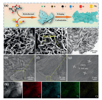
Fig. 1a describes the entire synthetic process of BNPC. First, the MgO template with a particle size of about 50 nm was prepared (Fig. S1 in Supporting information). Second, N-acetylglucosamine precursor was pyrolyzed onto the MgO surface under the hydrothermal condition. After that, the resultant was uniformly mixed with a certain amount of boric acid by grinding, followed by a simple one-step carbonization process. At last, the MgO template was fully removed by acid washing. Here, it should be mentioned that another product was totally solid carbon spheres at the absence of the MgO template (Fig. S2 in Supporting information), indicating the vital role of the template in the formation of porous structures.

|
Download:
|
| Fig. 1. (a) Schematic illustration of synthetic procedures of BNPC. (b, c) SEM images, (d-f) TEM images, (g) HRTEM image, and (h) STEM image and the EDX elemental mapping of BNPC. | |
Seen from SEM images (Figs. 1b and c), the as-synthesized BNPC product shows a well-defined morphology and unique 3D hierarchical nanostructure, which is well constructed by many thin carbon nanosheets. Meanwhile, these randomly stacked nanosheets are interconnected to each other to produce a large number of open spaces. That will be beneficial for the transmission and diffusion of electrons/ions, and alleviation of the large volume changes during cycles. The TEM image in Fig. 1d demonstrates that BNPC is mainly composed of folded interconnected nanosheets, which are well consistent with SEM observations. The detailed structure is further identified by the high magnification TEM images (Figs. 1e and f). Interestingly, it is found that many holes exist into the rough surface of carbon nanosheets, as framed by the yellow dash line. That may be caused by the released gas molecules from the decomposition of boric acid during carbonization process, manifesting the abundant porosity. Additionally, the NPC product exhibits a totally different structure (Fig. S3 in Supporting information), suggesting that the B doping process further induces the formation of such a unique hierarchical structure for BNPC. Fig. 1g shows the HRTEM image of BNPC. Clearly, it displays a relatively low crystallinity and expanded interlayer spacing of 0.364 nm, corresponding to the (002) crystal plane of carbon, which is larger than 0.335 nm of graphite [22]. STEM image and EDX elemental mapping (Fig. 1h) affirm the existence and good distributions of B and N elements in BNPC.
Fig. 2a shows XRD patterns of two products. There are two broad diffraction peaks centered at 25.4° and 42.9° in the NPC sample, corresponding to the (002) and (101) planes of carbon. That is the typical feature of amorphous carbon materials. Differently, the (002) broad peak of BNPC is shifted to the low degree at about 24.2°, suggesting an enlarged interlayer spacing. According to the Bragg equation, the layer spacing (002) of BNPC and NPC are calculated to be 0.365 nm and 0.34 nm, respectively, in line with the HRTEM analysis. The expansion reason for BNPC can be resulted from the boron and nitrogen co-doping. Raman spectroscopy is an effective tool to analyze the carbon microstructure. As displayed in Fig. 2b, the D band at 1340 cm−1 is described as the disordered carbon, whereas the G band at 1570 cm−1 is characteristic of graphitization carbon. And their ratio ID/IG usually reflects the graphitization degree of carbon materials [23]. BNPC shows a higher ID/IG of 1.04 than that of NPC (0.97), signifying the presence of more defects owing to the B,N co-doping into the carbon framework. The texture properties of two samples were further analyzed by N2 absorption-desorption isotherm. As shown in Fig. 2c, Figs. S4a and b (Supporting information), BNPC and NPC both show a type-Ⅳ hysteresis loop at the relative pressure of P/P0 = 0.5–0.9, indicating the appearance of mesopores [24]. The Barrett-Emmett-Teller (BET) surface area of BNPC is 528.5 m2/g, much higher than 361.6 m2/g of NPC. Importantly, the pore size distribution curve (inset of Fig. 2c) further illustrates two kinds of different mesopores centered at 3.7 and 15–33 nm, matching well with the SEM/TEM observations. Such a unique hierarchical nanostructure with large mesopores will in favor of the K+ fast transport dynamics.

|
Download:
|
| Fig. 2. (a) XRD patterns, (b) Raman spectra, (c) N2 sorption isotherm (inset of (c) is its pore size distribution curve). (d-f) High-resolution XPS spectra for C 1s, B 1s and N 1s of BNPC. | |
X-ray photoelectron spectroscopy (XPS) was further applied to detect the chemical state of BNPC. The high-resolution C 1s spectrum in Fig. 2d shows five peaks at the binding energy of 283.9, 284.81, 285.62, 286.54 and 289.18 eV, which are ascribed to C-B, C-C, C-O, C=O or C=C and O-C=O, respectively [25, 26]. Additionally, five peaks appear at the binding energy of 530.7, 531.6, 532.67, 533.86 and 535.23 eV in Fig. S5 (Supporting information), corresponding to O=N, C=O (O-Ⅰ), C-OH (O-Ⅱ), COOH (O-Ⅲ) and O-B, respectively [25]. Impressively, four distinct peaks exist in Fig. 2e, which belong to B-C (189.69 eV), B-C2O (190.73 eV), B-N (191.66 eV) and B-O or B-CO2 (192.42 eV) [27, 28], verifying the successful doping of B atoms. Fig. 2f presents the high-resolution N 1s spectrum of BNPC. That is deconvoluted into N-B (397.73 eV), pyridinic N (N-6, 398.8 eV), pyrrolic N (N-5, 399.7 eV), graphitic N (NQ, 401.23 eV) and N-O (403.17 eV), respectively [28]. The ratio of pyridine N and pyrrole N is about 43.1% and 34.9%, respectively (Fig. S6 in Supporting information). As reported, the existence of N-5 and N-6 can bring more additional defects, thereby improve the storage of K+ [26]. The quantitative analysis shows that about 6.79 at% boron and 7.18 at% nitrogen have been successfully incorporated into the carbon configuration (Fig. S7 in Supporting information). Such a high-level B,N co-doping is expected to improve the storage potassium performance thanks to the formation of more defects and increased active sites [29].
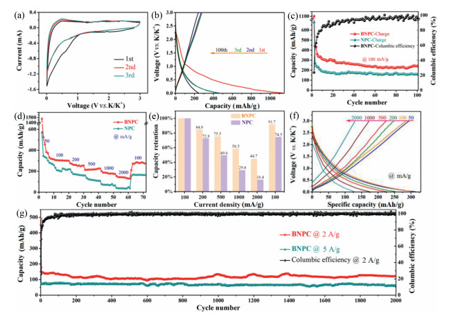
The electrochemical performances of BNPC and NPC electrodes as PIBs anodes were systemically studied. Fig. 3a illustrates the CV curves of the BNPC electrode for the initial three cycles at 0.1 mV/s. The CV curve of the first cycle exhibits anodic peak at 0.5 V, and cathodic peaks at 0.6 V. The cathodic peak at 0.6 V is attributed to the decomposition of the electrolyte and the generation of a solid electrolyte intermediate phase (SEI) [30], which obviously weakens in the second cycle. The broad anodic peak at near 0.5 V is related to the step potassiation process in carbon-based electrodes [31]. Importantly, CV curves almost overlap in the subsequent two cycles, indicating its excellent electrochemical reversibility. Fig. 3b shows charge/discharge profiles of BNPC electrode for the first three cycles within the voltage window of 0.01–3.0 V vs. K/K+ at 0.1 A/g. The initial discharge and charge capacities are 1135.5 and 269.5 mAh/g, respectively, showing an initial coulomb efficiency (ICE) of 23.7%. The initial large capacity loss is mainly due to the electrolyte decomposition and the SEI film formation [32]. Meanwhile, the low ICE can be enhanced by pre-potassiation strategy. In the second cycle, the CE value is increased to 58.9%, and then maintained at about 99.0% after 100 cycles, indicating that the irreversible capacity loss can be relieved during cycling.

|
Download:
|
| Fig. 3. (a) CV curves of the first three cycles at 0.1 mV/s. (b) GDC curves of BNPC electrode at 100 mA/g. (c) Cycling performances at 100 mA/g. (d) Rate capabilities at different current densities ranging from 50 mA/g to 2000 mA/g. (e) Capacity retention of BNPC and NPC electrodes. (f) GDC curves at different current densities. (g) Long cycling stabilities of BNPC electrode at 2000 mA/g and 5000 mA/g over 2000 cycles, respectively. | |
Fig. 3c displays the cycling stability of two electrodes. Obviously, the BNPC demonstrates a higher reversible capacity and better cycling stability than the control NPC. The charge capacity of BNPC still maintains to be 242.4 mAh/g and nearly 100% coulombic efficiency after 100 cycles at 0.1 A/g, while NPC only provides the capacity of 160 mAh/g. The rate performance of BNPC and NPC electrodes at current density from 0.05 A/g to 2 A/g are presented in Fig. 3d. Notably, BNPC exhibits high reversible specific capacities of 314.5, 301.2, 255.4, 227.1 and 176.1 mAh/g at current densities of 50, 100, 200, 500 and 1000 mA/g, respectively. Even at 2000 mA/g, a large reversible specific capacity of 134.5 mAh/g can still be reached. Moreover, when the current density was reset to 100 mA/g, a discharge capacity was recovered to 274.7 mAh/g for BNPC, illustrating an outstanding reversible stability at high current densities. That corresponds to the capacity retention of 100, 84.9, 75.5, 58.5, 44.7 and 91.7, respectively (Fig. 3e). In comparison, NPC has low reversible capacities of 259.5 and 36.1 mAh/g at current densities of 50 and 2000 mA/g, respectively. Fig. 3f shows the charge-discharge curves of BNPC at different current densities, implying capacitive-controlled storage processes. To better show the superiority of BNPC as anodes for PIBs, we also investigate its long-term cycling performance at 2000 mA/g and 5000 mA/g. As shown in Fig. 3g, BNPC still keeps a high reversible capacity of 123.1 mAh/g and 62.9 mAh/g after 2000 cycles, respectively, and large coulombic efficiency of nearly 100%. In contrast, NPC only delivers a low capacity of 58.0 mAh/g after 500 cycles at 2000 mA/g (Fig. S8 in Supporting information). Moreover, the BNPC electrode retains the 3D nanostructure well after cycling, which verifies its good structural stability (Fig. S9 in Supporting information). As listed in Table S1 (Supporting information), the BNPC anode for PIBs developed in the work outperforms most of the reported carbon-based anodes, highlighting the superiority of B,N co-doping.
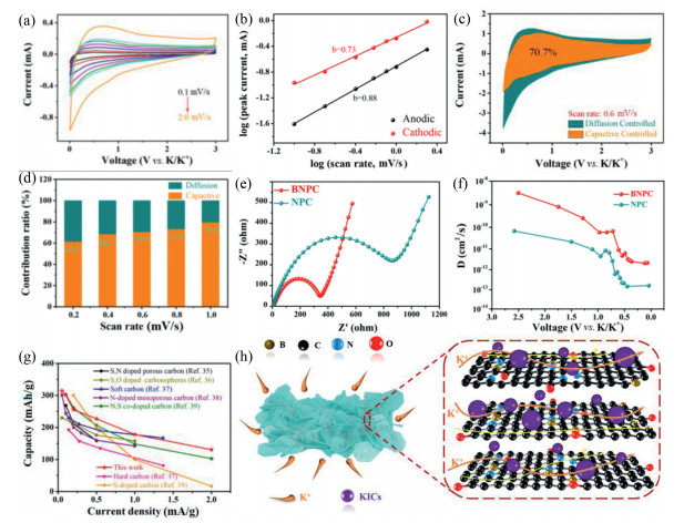
CV measurements at various scan rates ranging from 0.1 mV/s to 2.0 mV/s were further measured to investigate the potassium storage kinetics of BNPC and NPC (Fig. 4a and Fig. S10a in Supporting information). As shown in these curves, BNPC maintains the original shape, which becomes broader with increasing scan rates. Furthermore, even the scan rate reaches as high as 2.0 mV/s, the basic characteristics remain well, indicating that BNPC possesses a superior response capability to PIBs.

|
Download:
|
| Fig. 4. (a) CV curves of BNPC electrode at different scan rates. (b) b-values plotted for the anodic peak and cathodic peak. (c) Capacitive behavior (yellow region) and diffusion behavior (green region) contributions of BNPC at 0.6 mV/s. (d) Normalized contribution ratio of capacitive behavior and diffusion behavior capacities at different scan rates of BNPC. (e) Electrochemical impedance spectra of BNPC and NPC electrodes (inset of (e)) is the corresponding equivalent circuit). (f) K diffusion coefficients of BNPC and NPC electrodes. (g) Comparison of the potassium storage performances between the BNPC anode with previously reported carbonaceous materials. (h) Schematic illustration of possible potassium storage mechanism for BNPC. | |
The K+ storage contribution including the surface capacitive and diffusion contribution was investigated according to the power-law formula [33]:

|
(1) |
The b-value can be obtained to determine the electrochemical behavior predominated by semi-infinite diffusion (b~0.5) or capacitive process (b~1.0). In Fig. 4b, the anodic process exhibits b-value of 0.88, while cathodic process is 0.73. As a result, the electrochemical process is mainly determined by the surface capacitance, resulting from the high surface area and rich defects owing to the co-doping of B and N.
The following formula can be analyzed the contribution value of the capacitance control process:
|
(2) |
Fig. 4c shows a 70.7% of capacitive contribution (yellow region) from the total capacity at 0.6 mV/s for BNPC. Meanwhile, the capacitance contribution rate gradually increases as the scan rate increasing (Fig. 4d). When the scan rate is added from 0.2 mV/s to 1 mV/s, the capacitance contribution rate increases from 61.5% to 79.8%, much higher than those of NPC (Fig. S10b in Supporting information). The above results reveal that the capacitance-guided and diffusion-controlled processes are both embodied in the electrochemical reaction of BNPC, and the contribution rate of the surface dominant behavior is in a larger proportion. This high capacitance contribution is mainly due to the presence of many defects in the BNPC anode.
The electrochemical impedance spectra (EIS) of BNPC and NPC were also measured for further analysis of their diffusion kinetics. Fig. 4e shows the initial Nyquist plots of BNPC and NPC electrodes. The impedance spectrum contains an inclined line at the low frequency range and a concave semicircle at the high frequency range, which are assigned to the resistance to charge transfer (Rct) and Warburg impedance (Zw), respectively. The Z-view software analysis indicates that BNPC has a smaller resistance of 331.4 Ω than that of NPC (839.5 Ω), revealing a better conductivity and faster diffusion kinetics.
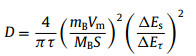
Galvanostatic intermittent titration (GITT) was applied to identify the K+ diffusion coefficient (D) of two electrodes under different voltages. DK value can be calculated by the following formula [34]:
|
(3) |
From the GITT results (Fig. 4f and Fig. S11), we can see that the D value of BNPC is 10−9 cm2/s to 10−12 cm2/s, while the NPC is 10−10 to 10−13, further verifying the faster diffusivity of K+ for BNPC. Impressively, the superior rate performance for potassium storage is comparable to most of previous carbon-based anodes, as summarized in Fig. 4g [35-39]. Fig. 4h describes the schematic diagram of possible storage potassium mechanism of BNPC. Considering that K ions tend to form K-intercalated carbon compounds (KICs) at defect sites [39], more additional defects brought by the B,N co-doping are favorable for the adsorption of K ions, and the unique hierarchical nanostructure can facilitate the rapid transport of K ions and electrons, thus boosting the potassium storage performance for BNPC anode.
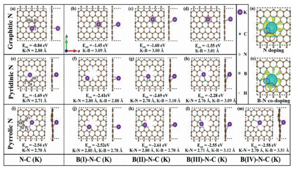
For the sake of clarifying the superior potassium storage performance, we then examine the adsorbed behavior of K ions on N-functionalized carbon (N-C) layers with and without the B doping. According to previous work [40], three types of N-C nanosheets are adopted in our calculations. As illustrated in Figs. 5a, e, i, the adsorption energies of K+ are −0.84, −1.69 and −2.54 eV for graphitic, pyridinic and pyrrolic N-C layer, respectively. The bond length of K-N in graphitic N case is significantly larger than other two cases, leading to much weaker K+ adsorption performance. As a result, K ions prefer to adsorb onto the pyrrolic N-C layer compared with graphilic and pyridinic ones.

|
Download:
|
| Fig. 5. The top and side views of K+ adsorption on (a) graphitic, (e) pyridinic- and (i) pyrrolic N-functionalized carbon (NC). The corresponding K adsorbed geometries of B-doped (b-d) graphitic, (f-h) pyridinic- and (j-m) pyrrolic-N functionalized carbon (B-N-C) at marked Ⅰ, Ⅱ, Ⅲ and Ⅳ sites, respectively. The adsorption energies and bond lengths of N-K and B-K are listed below each geometry. Purple, brown, gray, green and white spheres represent K, C, N, B and H atoms, respectively. (n, o) Charge density difference (isovalue of 0.001 e/Å3) for K adsorbed pyridinic-N functionalized carbon without and with B (Ⅱ) substitution. Cyan and yellow areas reflect the electron depletion and accumulation. Blue and red circles show the charge difference around doped N and B center, respectively. | |
The K+ adsorption on N-C layer after B doping (B-N-C) was further evaluated. Fig. 5 gives the corresponding adsorption energies and bond lengths of K-N and K-B for each K adsorbed B-N-C layer. Generally, the different B-doped sites show the small impact on the following K adsorption. For B-graphitic N-C case, the absolute values of the adsorption energies reach up to 1.60 eV, which is remarkably larger than that of graphilic N-C layer (0.84 eV), indicating the enhanced K+ adsorption performance. Despite of the initial position set for K+ adsorption, it largely shifts towards B side during relaxation, suggesting that B sites are more attractive for K+ adsorption than N sites. Besides, such enhanced performance also happens when B doping into the pyridinic and pyrrolic N-C nanosheets. In two cases, doped N and B atoms simultaneously work on and balances the K+ adsorption. Additionally, we also calculate the charge density difference of the K adsorbed pyridinic N-C with and without B(Ⅱ) doping. As displayed in Figs. 5n and o, the charge density around N site (blue circle) almost remains unchanged with and without the existence of B. However, the accumulated electrons around B (red circle) are remarkably increased in comparison to those around C or N, mainly resulting in the enhanced K+ adsorption performance. Taken together, the doping of B atoms will greatly improve the K+ capability of N-modified carbon layers.
To sum up, we have developed a scalable structural engineering technique for synthesis of B,N co-doped porous carbon nanosheets through a facile template-assisted route and simple carbonization process. Such a unique architecture can facilitate the transmission of ions/electrons, and the co-doping of B and N can increase the conductivity and offer more defects for K ions storage. All of the structural merits together account for the outstanding potassium storage capability. The constructed BNPC anode delivers a high reversible capacity (242.2 mAh/g at 100 mA/g after 100 cycles) and an outstanding long-term cycling stability (123.1 mAh/g at 2000 mA/g and 62.9 mAh/g at 5000 mA/g after 2000 cycles, respectively). The present study proposed can also provide a scalable feasibility for the development and design of advanced carbon-based electrode materials.
Declaration of competing interestThe authors declare that they have no known competing financial interests or personal relationships that could have appeared to influence the work reported in this paper.
AcknowledgmentsThe work was supported by Shuguang Program from Shanghai Education Development Foundation and Shanghai Municipal Education Commission (No. 18SG035), and State Key Laboratory for Modification of Chemical Fibers and Polymer Materials, Donghua University (No. KF2015).
Supplementary materialsSupplementary material associated with this article can be found, in the online version, at doi:10.1016/j.cclet.2021.06.063.
| [1] |
H.Y. Geng, Y. Peng, L.T. Qu, H.J. Zhang, M.H. Wu, Adv. Energy Mater. 10 (2020) 1903030. DOI:10.1002/aenm.201903030 |
| [2] |
Y.K. Sun, ACS Energy Lett. 4 (2019) 1042-1044. DOI:10.1021/acsenergylett.9b00652 |
| [3] |
J. Huang, X. Lin, H. Tan, B. Zhang, Adv. Energy Mater. 8 (2018) 1703496. DOI:10.1002/aenm.201703496 |
| [4] |
W. Zhang, J. Mao, Z. Chen, S. Li, Z. Guo, J. Am. Chem. Soc. 139 (2017) 3316-3319. DOI:10.1021/jacs.6b12185 |
| [5] |
C.H. Wu, H. Song, C. Tang, et al., Chem. Eng. J. 378 (2019) 122249. DOI:10.1016/j.cej.2019.122249 |
| [6] |
H. Kim, J.C. Kim, M. Bianchini, et al., Adv. Energy Mater. 8 (2018) 1702384. DOI:10.1002/aenm.201702384 |
| [7] |
Z.L. Jian, W. Luo, X.L. Ji, J. Am. Chem. Soc. 137 (2015) 11566-11569. DOI:10.1021/jacs.5b06809 |
| [8] |
Y.P. Li, Q.B. Zhang, Y.F. Yuan, et al., Adv. Energy Mater. 10 (2020) 2000717. DOI:10.1002/aenm.202000717 |
| [9] |
D.S. Bin, X.J. Lin, Y.G. Sun, et al., J. Am. Chem. Soc. 140 (2018) 7127-7134. DOI:10.1021/jacs.8b02178 |
| [10] |
C.H. Wu, J.Z. Ou, F.Y. He, et al., Nano Energy 11 (2019) 104061. |
| [11] |
Q. Ma, Y. Dai, H.R. Wang, et al., Chin. Chem. Lett. 32 (2021) 5-8. DOI:10.1016/j.cclet.2020.11.007 |
| [12] |
J.M. Chen, Y. Cheng, Q.B. Zhang, et al., Adv. Funct. Mater. 31 (2021) 2007158. DOI:10.1002/adfm.202007158 |
| [13] |
W. Wang, J. Zhou, Z. Wang, et al., Adv. Energy Mater. 8 (2018) 1701648. DOI:10.1002/aenm.201701648 |
| [14] |
T.T. Song, H.Y. Hong, Y. Hu, N.N. Sun, H.J. Zhang, Chin. Chem. Lett. 30 (2019) 2347-2350. DOI:10.1016/j.cclet.2019.07.024 |
| [15] |
J. Zhao, Y.F. Jiang, H. Fan, et al., Adv. Mater. 29 (2017) 1604569. DOI:10.1002/adma.201604569 |
| [16] |
H.J. Huang, R. Xu, Y.Z. Feng, et al., Adv. Mater. 32 (2019) 1904320. |
| [17] |
Z.Y. Sang, D. Su, J.S. Wang, Y. Liu, H.M. Ji, Chem. Eng. J. 381 (2020) 122677. DOI:10.1016/j.cej.2019.122677 |
| [18] |
M.H. Wu, Y.P. Gao, B. Zhao, Y. Hu, H.J. Zhang, Chin. Chem. Lett. 31 (2020) 897-902. DOI:10.1016/j.cclet.2019.07.039 |
| [19] |
D. Li, X. Ren, Q. Ai, et al., Adv. Energy Mater. 8 (2018) 1802386. DOI:10.1002/aenm.201802386 |
| [20] |
J.F. Ding, C. Tang, G.J. Zhu, et al., Mater. Chem. Front. 5 (2021) 825-833. DOI:10.1039/D0QM00598C |
| [21] |
W.X. Yang, J.H. Zhou, S. Wang, et al., ACS Energy Lett. 5 (2020) 1653-1661. DOI:10.1021/acsenergylett.0c00413 |
| [22] |
Z.P. Qiu, K.X. Zhao, J.M. Liu, S.B. Xia, Electrochim. Acta 340 (2020) 135947. DOI:10.1016/j.electacta.2020.135947 |
| [23] |
C.D. Elcey, B. Manoj, Asian J. Chem. 28 (2016) 1557-1560. DOI:10.14233/ajchem.2016.19750 |
| [24] |
J. Yang, Z. Ju, Y. Jiang, et al., Adv. Mater. 30 (2018) 1700104. DOI:10.1002/adma.201700104 |
| [25] |
Y. Zhang, X.D. Zhuang, Y.Z. Su, F. Zhang, X.L. Feng, J. Mater. Chem. A 2 (2014) 7742-7746. DOI:10.1039/c4ta00814f |
| [26] |
Q. Wang, Z.Y. Xie, Y.L. Liang, et al., Ionics (Kiel) 25 (2019) 2111-2119. DOI:10.1007/s11581-018-2647-7 |
| [27] |
H. Tabassum, R.Q. Zou, A. Mahmood, et al., Adv. Mater. 30 (2018) 1705441. DOI:10.1002/adma.201705441 |
| [28] |
Z. Ling, Z.Y. Wang, M.D. Zhang, et al., Adv. Funct. Mater. 26 (2016) 111-119. DOI:10.1002/adfm.201504004 |
| [29] |
D. Wang, Z. Wang, Y. Li, et al., Appl. Surf. Sci. 464 (2019) 422-428. DOI:10.1016/j.apsusc.2018.09.035 |
| [30] |
W. Yang, J. Zhou, S. Wang, et al., Energy Environ. Sci. 12 (2019) 1605-1612. DOI:10.1039/C9EE00536F |
| [31] |
L.J. Fu, K. Tang, K.P. Song, P.A.V. Aken, Y. Yu, Nanoscale 6 (2014) 1384-1389. DOI:10.1039/C3NR05374A |
| [32] |
Y. Liu, H.D. Dai, L. Wu, et al., Adv. Energy Mater. 9 (2019) 1901379. DOI:10.1002/aenm.201901379 |
| [33] |
L. Hu, B. Luo, C.H. Wu, et al., J. Energy Chem. 32 (2019) 124-130. DOI:10.1016/j.jechem.2018.07.008 |
| [34] |
Z.D. Lei, L.Q. Xu, Y.L. Jiao, et al., Small 14 (2018) 1704410. DOI:10.1002/smll.201704410 |
| [35] |
H.L. Ma, X.J. Qi, D.Q. Peng, et al., ChemistrySelect 4 (2019) 11488-11495. DOI:10.1002/slct.201903244 |
| [36] |
M. Chen, W. Wang, X. Liang, et al., Adv. Energy Mater. 8 (2018) 1800171. DOI:10.1002/aenm.201800171 |
| [37] |
Z.L. Jian, S.H. Wang, Z.F. Li, et al., Adv. Funct. Mater. 27 (2017) 1700324. DOI:10.1002/adfm.201700324 |
| [38] |
Z.P. Qiu, K.X. Zhao, J.M. Liu, S.B. Xia, Electrochim. Acta 340 (2020) 135947. DOI:10.1016/j.electacta.2020.135947 |
| [39] |
X.D. Shi, Y.D. Zhang, G.F. Xu, et al., Sci. Bull. 65 (2020) 2014-2021. DOI:10.1016/j.scib.2020.07.001 |
| [40] |
K. Zhang, Q. He, F.Y. Xiong, et al., Nano Energy 77 (2020) 105018. DOI:10.1016/j.nanoen.2020.105018 |