 2022, Vol. 33


b The Key Laboratory of Organic Optoelectronics & Molecular Engineering of Ministry of Education, Department of Chemistry, Tsinghua University, Beijing 100084, China;
c School of Materials Science and Engineering, Key Laboratory of Advanced Ceramics and Machining Technology of Ministry of Education, Tianjin Key Laboratory of Composite and Functional Materials, Tianjin University, Tianjin 300072, China
Hybrid supercapacitors (HSCs), combining the advantages of the high specific power of electric double-layer capacitive (EDLC) and the high specific energy of rechargeable batteries, attract extensive interest in the development and applications of modern electronic devices [1-3]. As the core part of supercapacitors (SCs), the electrochemical properties of electrode materials have a huge impact for commercial use. Typically, the energy storage mechanisms of electrode materials may be divided into two categories, include EDLC process and faradaic redox reaction, considerable efforts have been dedicated to the faradaic redox reaction electrodes to achieve higher energy density than EDLC materials [4, 5]. Due to the ultrahigh specific capacities and low costs, transition-metal-based compounds have been widely applied as battery-type electrode materials for HSCs [6]. So far, transition-metal-based oxides/hydroxide including Ni(Co)O [7-10], Co3O4 [11-13], Co(Ni)MoO4 [14-16], NiCo-LDH [17-20], etc. with various crystallographic structures were explored mainly as HSCs electrode materials. However, the low rate performance and inferior stability of these metal oxides/hydroxides were still hindered their potential usefulness because of their poor electrical conductivity, unstable structure and sluggish reaction kinetics [21-23]. Nanomaterials with small sizes and large surface areas, which provide enriched redox reaction sites and superior electronic conductivities, can significantly improve the electrochemical property [24, 25]. Therefore, it is necessary to develop novel nanomaterials with excellent conductivity and stability to overcome the shortfalls of transition metal oxides/hydroxides for improved electrochemical performance.
Transitional metal selenides (TMS) with high electrical conductivity, tunable electronic configuration and electrochemical activity [26, 27], have been regarded as a suitable electrode material for SCs. Up-to-now, TMS electrode materials, such as Ni3Se2 [28, 29], NiSe2 [30, 31], NiSe [32], CoSe [26] and NiCoSe2 [33-35], have been investigated for HSCs applications. Especially, Ni3Se2 is attracting attention in the field of HSCs due to its higher capability than Ni1-xSe and NiSe2 [28]. To make the most of the advantages of Ni3Se2 as battery-type materials for HSCs, nanoarchitecture engineering has been used to design high-performance nickel-based selenium compounds electrode materials for HSCs, such as mesoporous nanosheets [29], nanowires [36] and nano-dendrite arrays [28], have been explored as battery-type electrode materials for HSCs. At present, the in-situ growth of active nanomaterials on conductive substrates (such as Ni foam, NF) is an attractive approach and has been widespread applied in energy storage devices for outstanding performances. For instance, Chen et al. [28] prepared hierarchical Ni3Se2 nano-dendrite arrays on NF, which exhibited a high specific capacitance of 1234 F/g (3.70 F/cm2) at 1 A/g and outstanding rate capability. However, the nano-dendrite Ni3Se2 electrode materials suffered from poor electrochemical stability because of their unstable structure, which need further improvement. Furthermore, Wang et al. [36] also synthesized Ni3Se2 rich-grain-boundary nanowire arrays on NF by a solvothermal/selenization process. The Ni3Se2 nanowire arrays produced a high areal capacity (635 mAh/cm2 at 3 mA/cm2) and superior rate capability. Unfortunately, the approach required fussy, time-consuming and high-temperature processes, which posed a big challenge for scaling-up production. Thus, a simple and green method for large-scale production of Ni3Se2 nanomaterials with efficient and robust capacitor performance should be proposed and designed.
Herein, we rationally designed a hierarchical nanoarchitecture based on Ni3Se2 nanosheet-on-nanorods core-shell structure electrode materials (NSRx-Ni3Se2, x represents 0.5, 0.8 and 1.0) via a simple 3D NF-assisted solvothermal strategy. This freestanding 3D nanoarchitecture enhanced the contact area with the electrolyte and provided fast electron and ion transport channels, thus significantly improve the electrochemical performance. As a result, it exhibited a high specific capacity of 1.068 mAh/cm2 (7.69 F/cm2) at 2 mA/cm2 and an excellent rate performance. Furthermore, we assembled a HSC device based on the NSR0.8-Ni3Se2, which showed a fantastic energy density of 56.4 Wh/kg at 386.5 W/kg, an outstanding power density of 4640.3 W/kg at 39.7 Wh/kg and superior cycling performance (92.6% retention after 6000 cycles).
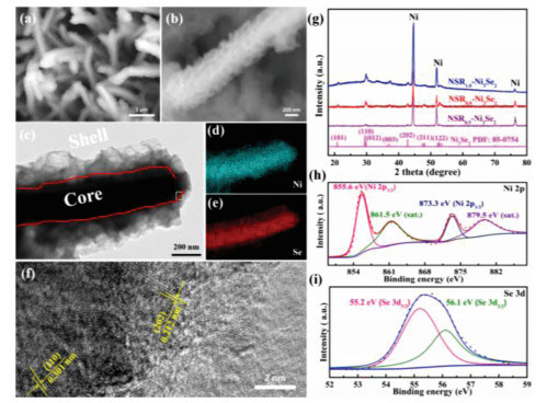
The novel NSRx-Ni3Se2 was fabricated via a simple 3D NF-assisted solvothermal strategy as shown in Fig. 1. The NF was immersed in a seed solution containing selenium (Se), where it underwent solvothermal treatment to initiate the in-situ formation of the Ni3Se2 nanosheet-on-nanorods core-shell structure. By changing the addition of Se (ranging from 0.5, 0.8, 1.0 mmol), the morphology of NSR-Ni3Se2 can be dramatically tuned (Fig. S1 in Supporting information), which were named as NSR0.5-Ni3Se2, NSR0.8-Ni3Se2, NSR1.0-Ni3Se2, respectively. When the amount of Se powder was 0.8 mmol, homogeneous Ni3Se2 arrays were in-situ grown on the NF (Figs. 2a and b, Figs. S1a and b). The NSR0.8-Ni3Se2 has an average diameter of ca. 400 nm, which showed nanosheet-on-nanorods core-shell structures (Figs. 2c and S2 in Supporting information). The corresponding elemental mapping images (Figs. 2d and e) revealed that the coexistence and uniform distribution of Ni and Se in a single NSR0.8-Ni3Se2. The high-resolution transmission electron microscopy (TEM) of the NSR0.8-Ni3Se2 showed lattice fringes with spacings of 0.212 nm and 0.301 nm, assigning to the (202) and (110) planes of Ni3Se2 respectively (Fig. 2f). This novel homogeneous nanostructure not only offers abundant energy storage active sites, but also promotes high-speed electron transfer, which can hugely improve the electrochemical performance. The crystal phase of the obtained NSRx-Ni3Se2 samples were characterized by XRD patterns (Fig. 2g). Except for the diffraction peaks at 44.50°, 51.80° and 76.37° for NF (PDF#04-0805), the diffraction peaks at 2θ angle of 20.94°, 29.58°, 29.97°, 37.17°, 42.62°, 47.68° and 52.73° corresponding to (101), (110), (012), (003), (202), (211) and (122) planes of Ni3Se2 (PDF#85-0754) respectively, are clearly appeared in all the three NSR-Ni3Se2 samples. X-ray photoelectron spectroscopy (XPS) spectrum was then employed to further confirm the chemical composition of the NSR-Ni3Se2 samples. The high-resolution Ni 2p spectrum (Fig. 2h) of NSR0.8-Ni3Se2 showed two major peaks at 855.6 eV (Ni 2p3/2) and 873.3 eV (Ni 2p1/2), which could be indexed to Ni2+ [36]. The other two small peaks at 861.5 eV and 879.5 eV belong to the shake-up satellites. The Se 3d XPS spectrum for the NSR0.8-Ni3Se2 (Fig. 2i) contains two peaks at 55.2 eV and 56.1 eV, corresponding to the metallic Se 3d and sulfur-metal bonds, respectively [33]. The above results indicated the successful formation of Ni3Se2 by the 3D NF-assisted solvothermal strategy.

|
Download:
|
| Fig. 1. Schematic illustration of the preparation process of the NSR-Ni3Se2 and its core-shell nanorod arrays on the NF. | |

|
Download:
|
| Fig. 2. (a, b) SEM images of NSR0.8-Ni3Se2. (c) TEM image of NSR0.8-Ni3Se2. (d, e) TEM-EDS elemental mapping images of a typical NSR0.8-Ni3Se2 core-shell nanorod. (c) HRTEM image of NSR0.8-Ni3Se2. (g) XRD patterns of Ni3Se2 samples. XPS spectra of NSR0.8-Ni3Se2: (h) Ni 2p, (i) Se 3d. | |
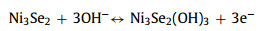
Electrochemical properties of the NSRx-Ni3Se2 samples were firstly analyzed by cyclic voltammetry (CV) in a three-electrode system at 2 mV/s (Fig. 3a). Compared to CV of NSR0.5-Ni3Se2 and NSR1.0-Ni3Se2, the voltammetric current response of NSR0.8-Ni3Se2 was much larger, implying the capacity of NSR0.8-Ni3Se2 was much higher than the other two counterparts. The redox reaction mechanism of Ni3Se2 can be described as the following equations in the KOH electrolyte:
|
(1) |

|
Download:
|
| Fig. 3. (a) CV curves of NSRx-Ni3Se2 samples. (b) CV curves of NSR0.8-Ni3Se2 at various scan rates. (c) GCD curves of NSRx-Ni3Se2 samples. (d) GCD curves of NSR0.8-Ni3Se2 at different current densities. (e) Areal capacity values of NSRx-Ni3Se2 samples at different current densities. (f) EIS spectra of NSRx-Ni3Se2 samples. | |
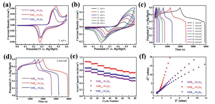
The CV curves of the NSR0.8-Ni3Se2 were also displayed from 2 mV/s to 20 mV/s with the increasing of the scan rates. As shown in Fig. 3b, the response current of the NSR0.8-Ni3Se2 rose linearly as scan rate increases and the CV plot shapes was highly stable, indicating the highly reversibility and ultrafast ion/charge transport kinetics of the NSR0.8-Ni3Se2. The reaction kinetics was further probed by analyzing the relationship between peak current (i) and scan rate (v) according to the following equations [37, 38]: i = avb, where a and b are constants. The b-values for the NSR0.8-Ni3Se2 were 0.58 and 0.52 (Fig. S3e in Supporting information), respectively, which indicated that the redox process in the NSR0.8-Ni3Se2 electrode material was dominated by a diffusion-controlled battery-type behavior [14]. Galvanostatic charge/discharge (GCD) analysis of the NSRx-Ni3Se2 was also evaluated at 2 mA/cm2 as shown in Fig. 3c. The battery-type of the two GCD profiles, namely latent voltage plateaus, confirmed that the faradaic reduction reactions were occurred during the charge-discharge processes, in good agreement with the aforementioned CV results. As a result, the charge-discharge time of the NSR0.8-Ni3Se2 electrode (3912 s) was much longer than that of the NSR0.5-Ni3Se2 electrode (2262 s) and the NSR1.0-Ni3Se2 electrode (3224 s, Fig. S3 in Supporting information), which could be attributed to its higher specific capacity of NSR0.8-Ni3Se. The GCD curves of the NSR0.8-Ni3Se2 (Fig. 3d) showed well defined potential plateaus and relatively symmetric shape at all the current densities, demonstrating its good battery-type property and high reversibility. Based on the GCD curves results, the areal specific capacity at different current densities of the NSRx-Ni3Se2 samples could be calculated as shown in Fig. 3e. The areal specific capacity values of the NSR0.8-Ni3Se2 were about 1.068 (7.69), 1.006 (7.24), 0.942 (6.78), 0.887 (6.31), 0.847 (6.10), 0.797 (5.74), 0.764 (5.50) and 0.729 (5.25) mAh/cm2 (F/cm2) at 2, 3, 5, 8, 10, 15, 20 and 30 mA/cm2, respectively, indicating the 68.3% retention of its initial capacity. In contrast, the capacity retentions of the NSR1.0-Ni3Se2 and the NSR0.5-Ni3Se2 were 64.5% and 60.9%, respectively. Notably, the superior specific capacity of the optimized NSR0.8-Ni3Se2 was highly competitive with those of the most previously reported nickel selenide-based electrodes and nickel-based electrodes (Table S1 in Supporting information).
The reaction kinetics of the NSRx-Ni3Se2 was explored by the electrochemical impedance spectroscopy (EIS, Fig. 3f). The slope of the NSR0.8-Ni3Se2 electrode was steeper than that of the NSR0.5-Ni3Se2 and NSR1.0-Ni3Se2 in the low frequency region, suggesting that the NSR0.8-Ni3Se2 electrode possess a short path for the electrons transportation and ions diffusion. The corresponding ohmic resistances for the NSRx-Ni3Se2 were 0.91 (NSR1.0-Ni3Se2), 0.86 (NSR0.8-Ni3Se2) and 0.81 (NSR0.5-Ni3Se2) Ω/cm2, respectively. This result suggests that the three NSRx-Ni3Se2 samples each have high electrical conductivity, while the NSR0.8-Ni3Se2 possesses the best electrochemical activity, which in turn indicates that the nanosheet-on-nanorods core-shell structure is very important to the performance. On the above basis, the significant enhancement in the capacitor performance of our 3D NF-assisted solvothermal strategy-derived NSR0.8-Ni3Se2 sample can be explained by the following reasons: (1) The in-situ preparation strategy guarantees the freestanding structure and robust support of electroactive materials of the hierarchical NSRx-Ni3Se2 on NF, which can significantly improve specific capacity and cycling stability. (2) The in-situ growth also reduces the interface resistance gap between the current collectors and electroactive materials, and acts as an electron superhighway to enhance the ion/electron transfer rate. (3) The hierarchical characteristic can offer a high specific surface area and plenty of active sites to store electrolyte ions, where the one-dimensional nanorod skeleton cannot only act as a high-speed electron transfer channel, but also can avoid the aggregation of the nanosheets. Additionally, the two-dimensional nanosheets provide numerous exposed active edge sites and protect the backbone from electrochemical corrosion.
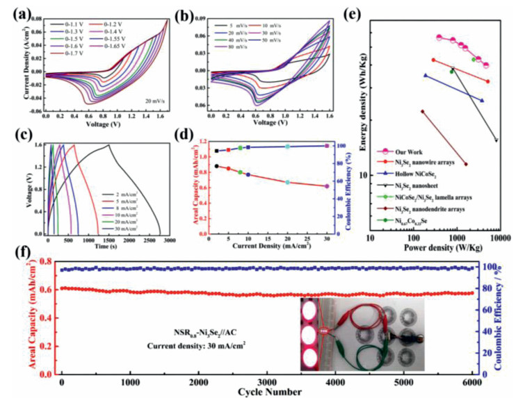
The electrochemical properties of the NSR0.8-Ni3Se2 materials for real application were also investigated by using two-electrode HSCs device, in which the NSR0.8-Ni3Se2 electrode materials were used as the cathode, active carbon (AC) was used as the anode, and a porous glassy fibrous paper was used as the separator. The NSR0.8-Ni3Se2/AC mass ratio is about 0.28 according to the equation: m+/m− = C−ΔE−/(C+ΔE+) [39]. To obtain the maximum capacity and proper voltage range for the NSR0.8-Ni3Se2//AC device, CV curves were tested at different voltage windows ranging from 0.0-1.1 V to 0.0–1.7 V. As shown in Fig. 4a, no apparent polarization even at the voltage window of up to 1.6 V was observed, suggesting that 0.0–1.6 V was an apropos voltage window for the NSR0.8-Ni3Se2//AC device. Fig. 4b showed that the NSR0.8-Ni3Se2//AC device had a superior stability over the voltage range of 0.0 V to 1.6 V, and no obvious distortion of the CV curves as scan rate increased, signifying that the fast and stable electron transfer kinetics of the as-assembled device. Furthermore, the GCD curves of the NSR0.8-Ni3Se2//AC device (Fig. 4c) were quasi-triangular shape with symmetric charge/discharge time, proving its excellent reversibility. Its areal specific capacity (Fig. 4d) reached 0.88 mAh/cm2 at 2 mA/cm2 that could maintain as 0.62 mAh/cm2 (70.4% retention of the initial capacity), meanwhile its coulombic efficiency was nearly 100% at 30 mA/cm2. Moreover, our HSCs device delivered an ultrahigh energy density of 56.4 Wh/kg at 386.5 W/kg, and the energy density could still remain 39.7 Wh/kg at 4640.3 W/kg (Fig. 4e). Compared with the previously reported nickel selenides-based electrodes [28, 29, 33, 34, 36, 40], our HSCs device shows an ultrahigh energy and power densities (Table S2 in Supporting information). The cycling stability of the HSC device was further explored at 30 mA/cm2 (Fig. 4f). It can be seen that the capacity retention is as high as 92.6% after 6000 cycles, accompanied by almost 100% coulombic efficiency, confirming that the excellent stability with high coulombic efficiency. Impressively, by assembling two HSCs devices in series, three red LEDs (the operating voltage and power is 2.0 V and 30 mW) can be easily lighted up, demonstrating the viability and potential of the HSCs device for practical applications.

|
Download:
|
| Fig. 4. (a) CV curves of HSCs measured at different operating voltages. (b) CV curves of HSCs at different scan rates. (c) GCD curves of HSCs at different current densities. (d) Specific capacities and Coulombic efficiencies for HSCs. (e) Energy density vs. power density compared with values reported previously. (f) cycling stability of NSR0.8-Ni3Se2//AC cell at 30 mA/cm2 (the insert: red LED powered by HSCs devices connected in series). | |
In summary, the hierarchical NSR-Ni3Se2 core-shell nanoarrays were designed as freestanding electrodes by a simple NF-assisted confinement assembly method, which presented excellent electrochemical performance for the HSCs device. The superior electrochemical performance was ascribed to the novel nanosheets wrapped nanorods core-shell architecture with significantly improved electroactive sites, the 3D network architecture with fast electron transfer channels, and the obviously enhanced contact area with the electrolyte. Our work not only developed a novel and efficient battery-type material, but also provided a simple approach to design 3D hierarchical nanostructures for energy storage devices.
Declaration of competing interestThe authors declare no conflict of interest.
AcknowledgementsWe acknowledge the financial support from the National Key R & D Program of China (Nos. 2017YFB1104300 and 2016YFA0200200) and National Natural Science Foundation of China (Nos. 21575014, 21905025, 91963113).
Supplementary materialsSupplementary material associated with this article can be found, in the online version, at doi:10.1016/j.cclet.2021.06.021.
| [1] |
A. Noori, M.F. El-Kady, M.S. Rahmanifar, et al., Chem. Soc. Rev. 48 (2019) 1272-1341. DOI:10.1039/C8CS00581H |
| [2] |
M. Wu, F. Chi, H. Geng, et al., Nat. Commun. 10 (2019) 2855. DOI:10.1038/s41467-019-10886-7 |
| [3] |
B. Lu, F. Liu, G. Sun, et al., Adv. Mater. 32 (2020) e1907005. DOI:10.1002/adma.201907005 |
| [4] |
S. Li, Y. Zhang, N. Liu, et al., Joule 4 (2020) 673-687. DOI:10.1016/j.joule.2020.01.018 |
| [5] |
Y. Jiang, J. Liu, Energy Environ. Mater. 2 (2019) 30-37. DOI:10.1002/eem2.12028 |
| [6] |
M. Dai, D. Zhao, X. Wu, Chin. Chem. Lett. 31 (2020) 2177-2188. DOI:10.1016/j.cclet.2020.02.017 |
| [7] |
H. Xu, Y. Cao, Y. Li, et al., J. Energy Chem. 50 (2020) 240-247. DOI:10.1016/j.jechem.2020.03.023 |
| [8] |
S. Liu, S.C. Lee, U.M. Patil, et al., J Mater. Chem. A 5 (2017) 4543-4549. DOI:10.1039/C6TA11049E |
| [9] |
W. Lu, J. Shen, P. Zhang, et al., Angew. Chem. 58 (2019) 15441-15447. DOI:10.1002/anie.201907516 |
| [10] |
Y. Li, Y. Shan, H. Pang, Chin. Chem. Lett. 31 (2020) 2280-2286. DOI:10.1016/j.cclet.2020.03.027 |
| [11] |
J. Huang, Y. Xiao, Z. Peng, et al., Adv. Sci. 6 (2019) 1900107. DOI:10.1002/advs.201900107 |
| [12] |
H. Wang, Q. Ren, D.J.L. Brett, et al., J. Power Sources 343 (2017) 76-82. DOI:10.1016/j.jpowsour.2017.01.042 |
| [13] |
X. Yin, H. Li, J. Lu, et al., J. Mater. Sci. Technol. 62 (2021) 60-69. DOI:10.1016/j.jmst.2020.05.066 |
| [14] |
S. Liu, Y. Yin, D. Ni, et al., Energy Storage Mater. 19 (2019) 186-196. DOI:10.1016/j.ensm.2018.10.022 |
| [15] |
P. Sun, W. He, H. Yang, et al., Nanoscale 10 (2018) 19004-19013. DOI:10.1039/C8NR04919J |
| [16] |
Y. Huang, C. Yan, X. Shi, et al., Nano Energy 48 (2018) 430-440. DOI:10.1016/j.nanoen.2018.03.082 |
| [17] |
X. Li, H. Wu, C. Guan, et al., Small 15 (2019) e1803895. |
| [18] |
H. Wang, J. Yan, R. Wang, et al., J Mater. Chem. A 5 (2017) 92-96. DOI:10.1039/C6TA08796E |
| [19] |
L. Zhang, S. Ji, R. Wang, et al., J. Alloy Compd. 810 (2019) 151871. DOI:10.1016/j.jallcom.2019.151871 |
| [20] |
F. Chen, H. Wang, S. Ji, et al., J. Alloy Compd. 785 (2019) 684-691. DOI:10.1016/j.jallcom.2019.01.235 |
| [21] |
J. Zhu, S. Tang, J. Wu, et al., Adv. Energy Mater. 7 (2017) 1601234. DOI:10.1002/aenm.201601234 |
| [22] |
F. Chen, C. Liu, B. Cui, et al., J. Power Sources 482 (2021) 228910. DOI:10.1016/j.jpowsour.2020.228910 |
| [23] |
F. Chen, H. Wang, S. Ji, et al., Sustain. Energy Fuels 2 (2018) 1791-1798. DOI:10.1039/C8SE00130H |
| [24] |
A. Molinari, P.M. Leufke, C. Reitz, et al., Nat. Commun. 8 (2017) 15339. DOI:10.1038/ncomms15339 |
| [25] |
W. Zuo, R. Li, C. Zhou, et al., Adv. Sci. 4 (2017) 1600539. DOI:10.1002/advs.201600539 |
| [26] |
J. Lin, H. Wang, Y. Yan, et al., J Mater. Chem. A 6 (2018) 19151-19158. DOI:10.1039/C8TA08263D |
| [27] |
T.T. Nguyen, J. Balamurugan, V. Aravindan, et al., Chem. Mater. 31 (2019) 4490-4504. DOI:10.1021/acs.chemmater.9b01101 |
| [28] |
L. Zhao, P. Zhang, Y. Zhang, et al., J. Mater. Sci. Technol. 54 (2020) 69-76. DOI:10.1016/j.jmst.2020.02.063 |
| [29] |
Y. Liu, Q. Xu, R. Wang, et al., J. Mater. Chem. A 8 (2020) 797-809. DOI:10.1039/C9TA11827F |
| [30] |
T. Hao, Y. Liu, G. Liu, et al., Energy Storage Mater. 23 (2019) 225-232. DOI:10.1016/j.ensm.2019.05.011 |
| [31] |
S. Wang, W. Li, L. Xin, et al., Chem. Eng. J. 330 (2017) 1334-1341. DOI:10.1016/j.cej.2017.08.078 |
| [32] |
S. Subhadarshini, E. Pavitra, G.S. Rama Raju, et al., ACS Appl. Mater. Inter. 12 (2020) 29302-29315. |
| [33] |
A. Meng, T. Shen, T. Huang, et al., Sci. China Mater. 63 (2019) 229-239. |
| [34] |
L. Hou, Y. Shi, C. Wu, et al., Adv. Funct. Mater. 28 (2018) 1705921. DOI:10.1002/adfm.201705921 |
| [35] |
G. Qu, X. Zhang, G. Xiang, et al., Chin. Chem. Lett. 31 (2020) 2007-2012. DOI:10.1016/j.cclet.2020.01.040 |
| [36] |
X. Shi, H. Wang, P. Kannan, et al., J. Mater. Chem. A 7 (2019) 3344-3352. DOI:10.1039/C8TA10912E |
| [37] |
F. Chen, H. Wang, S. Ji, et al., Mater. Today Energy 11 (2019) 211-217. DOI:10.1016/j.mtener.2018.12.002 |
| [38] |
W. Lu, J. Shen, P. Zhang, et al., Angew. Chem. 58 (2019) 15441-15447. DOI:10.1002/anie.201907516 |
| [39] |
F. Chen, X. Cui, C. Liu, et al., Sci. China Mater. 64 (2020) 852-860. |
| [40] |
H. Chen, S. Chen, M. Fan, et al., J. Mater. Chem. A 3 (2015) 23653-23659. DOI:10.1039/C5TA08366D |