 2022, Vol. 33


Lithium-sulfur (Li‒S) batteries have become a very promising next-generation energy battery due to the high theoretical energy density (2600 Wh/kg), environmental friendliness, and abundant S reserve [1-6]. However, the practical application of Li‒S batteries have been severely hindered due to the capacity attenuation caused by the side reaction between polysulfides (PSs) in electrolyte and Li metal anode [7-9]. So far, the side reaction is rarely discussed from the perspective of the anode protection in previous reports. Under the action of concentration field, the soluble high-order PSs can migrate to the side of the Li metal anode and then react with it to form low-order PSs. Moreover, under both the action of concentration field and electric field, low-order PSs can move back to the side of the cathode and react with it, resulting in the loss of active materials such as S and Li. The successive reactions cause serious decline of capacity [10]. Hence, it is urgent to develop a strategy to mitigate the side reaction for high-capacity retention in Li‒S batteries.
Among all methods, the artificial protective film is a feasible strategy to suppress the occurrence of the side reaction [11-14]. As a representative work, Lai's group fabricated an in-situ artificial protective film through the chemical reaction between Mg2N3 and Li foil for stable lithium anode [15]. Regrettably, the PSs in electrolyte could infiltrate into the protective film and react with the Li metal anode, which would result in the formation of Li2S on the surface of the Li anode [16]. The Li2S will exacerbate the instability of the routine solid electrolyte interface (SEI) film, and further aggravate the anode failure [17]. Therefore, it is very difficult for the individual inorganic films as the protective film of the Li anode to protect it. The mixed application of inorganic and organic materials as the protective film was suggested [18]. In which, organic materials can efficiently inhibit the PSs in electrolyte to infiltrate into the protective film, while inorganic materials can improve the lithium-ionic conductivity and the mechanical strength of the protective film [10, 19-21]. Based on this consideration, Nafion materials are usually applied [10, 18]. It is attributed to that (ⅰ) the Nafion materials exhibit a stable electrochemical performance, (ⅱ) the Nafion has a high-lithium-affinity feature, and (ⅲ) the Nafion molecule chain contains the sulfonate group (-SO3−), which can prevent PSs from contacting with the Li anode by static electricity [22-26]. As a representative work, our group achieves a stable Li metal electrode in Li‒S batteries by the Nafion-based double-layer protective film [10]. The outstanding performance indicated the positive effect of the Nafion-based film for the Li metal anode protection. Unfortunately, in this work, the side reaction is simply concerned. It is necessary to understand the side reaction and suppress it. Herein, we propose a protective film being consisted of the TiO2 and Nafion (The detailed experimental section could be found in Supporting information.), in which TiO2 could not only increase the ionic conductivity and the mechanical strength of the film, but also make the film's electrical potential more negative thanks to the synergistic effect of Nafion and TiO2 for inhibiting the infiltration of PSs to suppress the side reaction [27-29]. In a word, the composite film can not only alter the interface properties of the Li metal anode to promote the uniform lithium plating, but also suppress the side reaction for high-capacity retention in Li‒S batteries. The ionic conductivity and electrical potential of the protective film are adjusted by changing the content of TiO2 [27, 30-33]. The optimized Li-Nafion/TiO2 with 0.10 wt% TiO2 (denoted as LNT-0.10) film exhibits a much higher lithium-ion conductivity and a lower negative electrical potential. Therefore, the symmetric cells, using the Li foil protected by LNT-0.10 (denoted as LLNT-0.10) as electrodes, exhibit the extended cycle-life in Li2S8 electrolyte for 750 h at a current density of 1 mA/cm2 with a fixed capacity of 1 mAh/cm2 and 420 h at an ultra-high-capacity density of 10 mAh/cm2 thanks to the presence of the composite film. Moreover, the symmetric cell shows a longer cycle-life (175 h) than the pure Li anode (70 h) in Li2S8 electrolyte, using the ultra-thin Li anode protected by LNT-0.10, with the thickness of 50 μm. The Li‒S full batteries with a LLNT-0.10 anode also exhibit higher capacity retention of 777.4 mAh/g and better rate performance of 550.7 mAh/g at 1 C. These results successfully demonstrate the feasibility of the synergistic effect of Nafion and TiO2 to suppress the side reaction for high capacity retention in Li-S batteries.
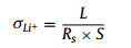
The preparation progress of the Li metal protected by Li-Nafion/TiO2 (LLNT) electrodes is shown in Fig. 1a. Firstly, the Li-Nafion solution (15 µL) was dripped on a Li foil and dried at room temperature for 12 h. The top-view SEM image of the electrode shows a smooth and flat surface, as shown in Fig. 1b. After drying, Li-Nafion/TiO2 (LNT) solutions (35 µL) with different TiO2 contents were dripped on the resulting electrodes and dried at 60 ℃ for 12 h to form an artificial protective film. The thickness of LNT-0.10 artificial film is approximate 1.5 µm (Fig. S1 in Supporting information). The color of the electrodes changes from silvery-white to off-white. Their top-view scanning electron microscopy (SEM) images are shown in Figs. 1c–e. From the SEM images in Figs. 1c–e, many white spots on the surface of LLNTs are observed, indicating the existence of TiO2 nanoparticle clusters due to the addition of TiO2. As shown in Fig. S2 (Supporting information), the element mapping images of Nafion/TiO2 film demonstrate that TiO2 nanoparticles are uniformly dispersed in Nafion. To further reveal the composition of protective films, X-ray diffraction (XRD) analysis was employed. Fig. S3 (Supporting information) shows the XRD patterns of the steel sheet, Li-Nafion/TiO2 films with different TiO2 contents and the standard card of TiO2 (JCPDS No. 34–180). The reason for choosing steel sheet is to avoid the appearance of the corresponding peaks caused by the lithium metal oxidation. In Fig. S3, XRD peaks at 43.8°, 51.2° are attributed to the pure steel sheet, and the XRD peak centered at 17.3° originates from the sulfonate ion chain of Nafion [18]. In addition, the XRD peak at 27.3° is labeled to (110) plane of TiO2. Moreover, as shown in Fig. S4 (Supporting information), the characteristic absorption bands of Nafion centered at 1213, 1147 and 980 cm−1 can be clearly observed in FT-IR spectra. In addition, the absorption bands centered at 1648 and 1058 cm−1 are attributed to the lithium sulfonate, further confirming the existence of Nafion [18]. The lithium-ionic conductivity of a protective film is an important parameter to determine the lifetime of a lithium anode. It is calculated from Eq. 1 [34]:
|
(1) |

|
Download:
|
| Fig. 1. (a) The fabrication process of protected electrodes. Top-view SEM images of (b) LLNT-0, (c) LLNT-0.05, (d) LLNT-0.10, (e) LLNT-0.20 electrode surfaces. | |
The higher lithium-ionic conductivity stands for the better ability of the protective film to redistribute the lithium ions flux for achieving a stable anode [35]. Electrochemical impedance spectroscopy (EIS) of the protective films are shown in Fig. S5 (Supporting information), the LLNT-0.10 electrode exhibits the lowest equivalent series impedance compared to the other electrodes, indicating the highest lithium-ionic conductivity of the LLNT-0.10 electrode. From Fig. 2a, the pure Li-Nafion film exhibits the lowest ionic conductivity (4.19 × 10⁻⁵ S/cm), while the LNT-0.10 film exhibits the highest ionic conductivity (36.1 × 10⁻⁵ S/cm), due to the incorporation of the TiO2. However, when TiO2 content reaches the 0.20 wt%, the ionic conductivity of the LNT-0.20 film appears to decrease, which could be due to the reason that the larger size and higher density of TiO2 nanoparticle clusters hinder the lithium ion migration [18]. To further investigate the effect of the protective films on the lithium-ion nucleation overpotential, Li-Cu batteries were fabricated. The LNT-0.10 film exhibits the lowest lithium-ion nucleation overpotential (23 mV), indicating that it is favorable for lithium ions to migrate compared to the other protective films (Fig. 2b). In other words, the LNT-0.10 film can promote a stable and uniform deposition of lithium ions. To know the capacity of protective films for inhibiting the side reaction, the zeta potential was performed. The more negative zeta potential is, the better inhibitory effect on LiPSs does [10, 22-26]. From the Fig. 2c, the absolute zeta potential value gradually increases with the increase of TiO2 content. This is because that the introduction of TiO2 results in the long chain of sulfonate ions of Nafion into short chain by the electrostatic interaction, exposing more negative charged sites [28, 29]. Among all Li-Nafion-based protective films, the LNT-0.10 film shows the most negative zeta potential (−5.46 mV), indicating its excellent inhibition effect on LiPSs. With the addition of TiO2, the absolute value of zeta potential of Nafion/TiO2 first increases because the TiO2 nanoparticles change the shape of the ionic cluster and increases the density of the negatively charge sites (-SO3− on the side chains) [18]. However, the TiO2 content is further increased (reaching 0.20 wt%), and aggregation of TiO2 nanoparticles would occur (Fig. 1e), leading to that the specific surface area of the corresponding TiO2 becomes small and the ability to change the shape of the ionic cluster begins to become weak. To further prove this result and further understand the corrosion resistance of different electrodes, we conducted an electrode corrosion experiment. The pure Li foil, LLNT-0, LLNT-0.05, LLNT-0.10 and LLNT-0.20 were put into 5 mL of 4 mmol/L Li2S8 solution, respectively. After Li2S8 fully reacts with the Li metal anode, we measured the residual concentration of Li2S8 in the solution by ultraviolet-visible absorption spectrum to judge the degree of the side reaction. The higher Li2S8 concentration is remained, the higher corrosion resistance of the electrode is achieved. As shown in Fig. 2d, among all the solutions, the solution containing LLNT-0.10 possesses the highest concentration of Li2S8, which is close to the original Li2S8 solution, further confirming the suitable TiO2 content plays an important role in inhibiting the occurrence of the side reaction.

|
Download:
|
| Fig. 2. (a) Lithium-ionic conductivity and (b) lithium-ionic nucleation overpotential of Nafion/TiO2 film with different contents of TiO2. Zeta potentials of (c) different protective films and (d) UV–vis absorption spectra of different protective films. (e) Cycling life of symmetric cells with different electrodes in Li2S8 electrolyte at the current density of 1 mA/cm2 and capacity density of 1 mAh/cm2. | |
The mechanical properties of the protective films are also an important parameter. The mechanical properties of the protective films were studied by atomic force microscopy (AFM). As shown in Figs. S6 and S7 (Supporting information), the mechanical strength of LNT-0.10 film (3.28 GPa) is much higher than that of LNT-0 film (1.44 GPa), suggesting that the incorporation of TiO2 makes the protective film become tougher to adapt to the changes of the Li anode volume.
Subsequently, Li, LLNT-0, LLNT-0.05, LLNT-0.10 and LLNT-0.20 symmetric cells were assembled with Li2S8 electrolyte to testify the repellent effect of the protective films on LiPSs in the electrolyte. As shown in Fig. 2e, the pure Li electrode exhibits the initial polarization of 100 mV and the cycle life of 140 h at the current density of 1 mA/cm2 and the capacity of 1 mAh/cm2. Apparently, as shown in Fig. S8 (Supporting information), the polarization increases suddenly to 210 mV when the battery cycles for 180 h. Such a phenomenon could be caused by the severe corrosion of Li2S8 in electrolyte (Figs. S10a and b in Supporting information) [10]. Excitingly, as shown in Fig. 2e, LLNT-0.10 exhibits the lowest initial polarization of 70 mV and the longest cycle-life (750 h). The polarization of LLNT-0.10 remains unchanged at about 70 mV when the battery cycles for around 670 h (Fig. S9 in Supporting information). It could be attributed to the side reaction to be well suppressed (Figs. S10c and d in Supporting information). Although LLNT-0, LLNT-0.05, LLNT-0.20 also show an extended cycle-life, the batteries still fail at only 250 h, 330 h and 300 h, respectively. The failure of these batteries is mainly due to the insufficient suppression of the side reaction.
In order to further understand the effect of the protective films on the Li anode, the batteries were disassembled after 15 cycles at a current density of 1 mA/cm2 and a capacity of 1 mAh/cm2. From the top-view SEM images in Figs. S10a and b, a rough and looser structure with some holes and cracks is observed on the surface of the pure Li anode, which could be caused by seriously corrosive effect of Li2S8. In contrast, as shown in Figs. S10c and d, a smoother and compact structure is observed on the surface of the LLNT-0.10 anode, indicating that the Li electrode corrosion is well suppressed. The Li striping morphologies on Li and LLNT-0.10 electrodes were also detected to account for the stability of anodes. Figs. S11a and b (Supporting information) show the pure Li anode surface with some holes and cracks, demonstrating uneven Li ion extraction and serious electrode corrosion. Differently, a smooth and flat striping surface is detected on the LLNT-0.10 anode, which proves the integrity and excellent protection effect of the film to the Li anode (Figs. S11c and d in Supporting information). In the corresponding optical image, we observe the surface of LLNT-0.10 remains unchanged as cycling before. However, the surface of the pure Li anode has turned from metallic bright white to black, which could be caused by the corrosion of Li2S8 in electrolyte. Fig. S12 (Supporting information) shows the Li deposited morphologies on the surface of the pure Li and LLNT-0.10 electrodes at a current density of 5 mA/cm2 and capacity 5 mAh/cm2. The surface of the LLNT-0.10 electrode (Figs. S12c and d) is flatter than the pure Li electrode (Figs. S12a and b), which can further confirm the excellent protective effect of the Nafion/TiO2 film.
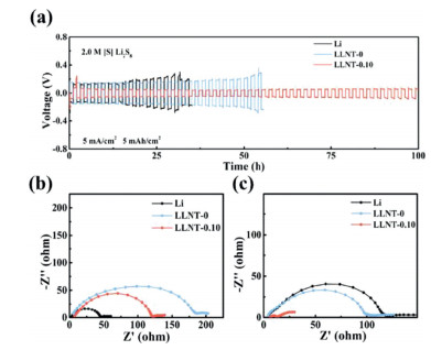
In addition, the charge-discharge curves of voltage-time were performed at a high current density and high-capacity of 5 mA/cm2 and 5 mAh/cm2. In Fig. 3a, the LLNT-0.10 anode exhibits a much longer cycle life (100 h) than the pure Li anode (20 h) and LLNT-0 anode (50 h). The extended cycle-life could be mainly attributed to the suppression of the electrode corrosion. The EIS measurements were also made. In Fig. 3b, the pure Li anode exhibits the lowest impedance (48 Ω) for the transportation of Li ions through SEI (RSEI) before cycling. However, LLNT-0.10 (120 Ω) and LLNT-0 (183 Ω) exhibits a much higher RSEI than the pure Li anode, which is due to the presence of protective films to hinder the lithium-ion transmission [10, 18]. Unfortunately, the RSEI of the pure Li anode increases to 126 Ω after 5 cycles at high current density, while the RSEI of LLNT-0.10 rapidly decreases to 14 Ω (Fig. 3c) due to infiltration of electrolyte into the protective film during cycling and the excellent protection of the Li anode [10]. Moreover, the electrode thickness and volume expansion rate were calculated to compare the stability of anodes by the cross-sectional SEM images (theoretically, 1 mAh/cm2 for Li corresponds to 4.85 µm). In Fig. S13 (Supporting information), after plating the capacity of 5 mAh/cm2 on different electrodes, the pure Li anode exhibits a looser structure with the thickness of 51.7 µm and suffers a much larger volume expansion rate of 113%, while the LLNT-0.10 exhibits a compact structure with the thickness of 33.2 µm and a lower volume expansion rate of 36% (Fig. S14 in Supporting information). This is because the composite film could not only prevent the corrosion from PSs, but also promote the lithium-ion flow to plate evenly. Moreover, the stable performance of the LLNT-0.10 symmetric cell with ultra-high-capacity of 10 mAh/cm2 can be up to 420 h (Fig. S15 in Supporting information). These results have successfully proved the outstanding protective effect of the composite film. In order to explore whether the protective film can achieve a stable anode cycle for an ultra-thin Li foil with a thickness of 50 µm, the symmetric cells were assembled, using Li2S8 electrolyte. In Fig. S16 (Supporting information), the LLNT-0.10 still shows an extended cycle life (175 h) compared to the pure Li electrode (around 70 h). These results illustrate that the protective film is also feasible under the ultra-thin lithium foil batteries.

|
Download:
|
| Fig. 3. (a) Voltage-time curves of Li, LLNT-0 and LLNT-0.10 symmetric cells at a current density of 5 mA/cm2 and capacity density of 5 mAh/cm2 in Li2S8 electrolyte. EIS of Li, LLNT-0 and LLNT-0.10 symmetric cells (b) before cycling and (c) after cycling. | |
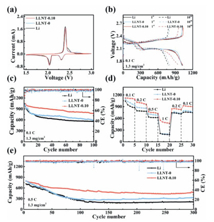
The specific Li‒S batteries were assembled for testing the shuttle current, using C/S as cathodes with the average sulfur loading of 1.3 mg/cm2, pure Li and LLNT-0.10 as anodes and 40 µm ether-based electrolyte without LiNO3 as electrolyte. In Fig. S17 (Supporting information), the battery with LLNT-0.10 anode shows the much lower shuttle current compared to the battery with the pure Li anode, demonstrating the side reaction is well suppressed by the LNT-0.10 film. Moreover, Li‒S full batteries were assembled using standard ether-based Li‒S electrolyte, C/S as cathodes and Li, LLNT-0, 0.10 as anodes. In Fig. 4a, CV curves exhibit the almost identical redox peaks, implying the presence of protective films did not affect the kinetics of redox reaction [10]. In addition, galvanostatic charge-discharge (GCD) profiles were also performed at the current density of 0.1 C with average sulfur loading of 1.3 mg/cm2. In Fig. 4b, the battery with the pure Li anode exhibits the initial capacity of 1021.6 mAh/g and decays to 780.9 mAh/g after 10 cycles at 0.1 C. In sharp contrast, the battery with LLNT-0.10 anode exhibits a similar initial capacity of 1037.3 mAh/g, but it can still remain a high capacity of 957.1 mAh/g after 10 cycles at 0.1 C. The Li-S battery with LLNT-0 anode exhibits the initial capacity of 1014.6 mAh/g and a capacity retention of 800.7 mAh/g. The higher capacity retention of LLNT-0.10 could be attributed to the excellent suppression of the side reaction. Fig. 4c shows their cycling performances at 0.1 C. The capacity of the battery with LLNT-0.10 anode decreases from 1037.3 mAh/g to 777.4 mAh/g with a capacity retention rate of 74.9% after 100 cycles. The batteries with the pure Li anode and LLNT-0 anode exhibit the capacity retention of 557.4 and 593.2 mAh/g with capacity retention rate of 54.5 and 58.4% after 100 cycles. The rate performances are shown in Fig. 4d. The battery with the LLNT-0.10 exhibits a much higher discharge capacity retention of 550.7 mAh/g at the current density of 1 C compared to the pure Li anode (212.7 mAh/g) and LLNT-0 anode (214.5 mAh/g). In addition, when the current density is decreased from 1 C to 0.1 C, the LLNT-0.10 anode still maintains the higher discharge capacity of 926.3 mAh/g than the pure Li anode (754.3 mAh/g) and LLNT-0 anode (791.1 mAh/g), indicating the side reaction is well suppressed by the synergistic effect of the Li-Nafion and TiO2 in the LNT-0.10 film. Moreover, the cycle performances for 300 cycles at 0.5 C are shown in Fig. 4e, the batteries with the pure Li anode, LLNT-0 anode and LLNT-0.10 anode exhibit the similar initial capacity of 743.2 mAh/g, 820 mAh/g and 789.1 mAh/g. However, LLNT-0.10 anode maintains the higher capacity and capacity retention rate of 466.1 mAh/g and 59.07% compared to the pure Li anode (211 mAh/g and 28.39%) and LLNT-0 anode (330.4 mAh/g and 40.29%).

|
Download:
|
| Fig. 4. (a) CV curves in the voltage range of 1.5 V-3 V. (b) 1st and 10th GCD curves at 0.1 C. (c) Cycle performances at 0.1 C for 100 cycles. (d) Rate performance at different rates. (e) Cycle performances at 0.5 C for 300 cycles for Li‒S batteries with Li, LLNT-0 and LLNT-0.10 as anodes in standard Li‒S electrolyte. | |
In summary, the Li-Nafion/TiO2 composite films were fabricated and showed high lithium ionic conductivity, high mechanical properties and negative zeta potential. The LNT-0.10 is an optimized protective film in our experiment. The LLNT-0.10 symmetric cell achieves an extended cycle-life of 750 h and the Li‒S full battery with the LLNT-0.10 as an anode delivers a high-capacity retention rate of 74.9% and the better rate performance of 550.7 mAh/g at 1 C. The improvement of the electrochemical performance could be attributed to the result that the side reaction is completely suppressed. Our work provides alternative insights into exploring the inhibitory effect of the artificial protective film on the side reaction.
Declaration of competing interestThe authors declare that they have no known competing financial interests or personal relationships that could have appeared to influence the work reported in this paper.
AcknowledgmentsThis study was partially supported by grants from the National Natural Science Foundation of China (Nos. 51772069 and 52072099).
Supplementary materialsSupplementary material associated with this article can be found, in the online version, at doi:10.1016/j.cclet.2021.05.065.
| [1] |
H.J. Peng, J.Q. Huang, X.B. Cheng, Q. Zhang, Adv. Energy Mater. 7 (2017) 1700260. DOI:10.1002/aenm.201700260 |
| [2] |
A. Manthiram, Y. Fu, S.H. Chung, C. Zu, Y.S. Su, Chem. Rev. 114 (2014) 11751-11787. DOI:10.1021/cr500062v |
| [3] |
R. Van-Noorden, Nature 498 (2013) 416-417. DOI:10.1038/498416a |
| [4] |
M. Zhao, B.Q. Li, X.Q. Zhang, J.Q. Huang, Q. Zhang, ACS Cent. Sci. 6 (2020) 1095-1104. DOI:10.1021/acscentsci.0c00449 |
| [5] |
M. Zhao, Y.Q. Peng, B.Q. Li, X.Q. Zhang, J.Q. Huang, J. Energy Chem. 56 (2021) 203-208. DOI:10.1016/j.jechem.2020.07.054 |
| [6] |
M. Zhao, X. Chen, X.Y. Li, B.Q. Li, J.Q. Huang, Adv. Mater. 33 (2021) 2007298. DOI:10.1002/adma.202007298 |
| [7] |
S. Xiong, K. Xie, Y. Diao, X. Hong, J. Power Sources 246 (2014) 840-845. DOI:10.1016/j.jpowsour.2013.08.041 |
| [8] |
L. Chen, L.L. Shaw, J. Power Sources 267 (2014) 770-783. DOI:10.1016/j.jpowsour.2014.05.111 |
| [9] |
H.J. Peng, J.Q. Huang, Q. Zhang, Chem. Soc. Rev. 46 (2017) 5237-5288. DOI:10.1039/C7CS00139H |
| [10] |
Q. Jin, X. Zhang, H. Gao, L. Li, Z. Zhang, J. Mater. Chem. A 8 (2020) 8979-8988. DOI:10.1039/D0TA02999H |
| [11] |
N. Akhtar, X. Sun, M.Y. Akram, et al., J. Energy Chem. 52 (2021) 310-317. DOI:10.1016/j.jechem.2020.04.046 |
| [12] |
J.Y. Wei, X.Q. Zhang, L.P. Hou, et al., Adv. Mater. 32 (2020) 2003012. DOI:10.1002/adma.202003012 |
| [13] |
R. Xu, C. Yan, J.Q. Huang, Trends Chem. 3 (2020) 5-14. |
| [14] |
H. Lu, N. Xu, X. Ni, et al., J. Energy Chem. 58 (2021) 78-84. DOI:10.1016/j.jechem.2020.08.062 |
| [15] |
Q. Dong, B. Hong, H. Fan, et al., ACS Appl. Mater. Inter. 12 (2020) 627-636. DOI:10.1021/acsami.9b16156 |
| [16] |
W. Li, H. Yao, K. Yan, et al., Nat. Commun. 6 (2015) 7436. DOI:10.1038/ncomms8436 |
| [17] |
C. Zu, A. Manthiram, J. Phys. Chem. Lett. 5 (2014) 2522-2527. DOI:10.1021/jz501352e |
| [18] |
S. Jiang, Y. Lu, Y. Lu, et al., Chem. Asian J. 13 (2018) 1379-1385. DOI:10.1002/asia.201800326 |
| [19] |
W. Liu, W. Li, D. Zhuo, et al., ACS Cent. Sci. 3 (2017) 135-140. DOI:10.1021/acscentsci.6b00389 |
| [20] |
Y. Tominaga, I.C. Hong, S. Asai, M. Sumita, J. Power Sources 171 (2007) 530-534. DOI:10.1016/j.jpowsour.2007.06.007 |
| [21] |
V. Ramani, H.R. Kunz, J.M. Fenton, J. Membrane Sci. 232 (2004) 31-44. DOI:10.1016/j.memsci.2003.11.016 |
| [22] |
C. Shen, M. Ge, A. Zhang, et al., Nano Energy 19 (2016) 68-77. DOI:10.1016/j.nanoen.2015.11.013 |
| [23] |
Z. Hao, L. Yuan, Z. Li, et al., Electrochim. Acta 200 (2016) 197-203. DOI:10.1016/j.electacta.2016.03.166 |
| [24] |
J. Song, M.J. Choo, H. Noh, J.K. Park, H.T. Kim, ChemSusChem 7 (2014) 3341-3346. DOI:10.1002/cssc.201402789 |
| [25] |
Y. Cao, X. Li, I.A. Aksay, et al., Phys. Chem. Chem. Phys. 13 (2011) 7660-7665. DOI:10.1039/c0cp02477e |
| [26] |
T.Z. Zhuang, J.Q. Huang, H.J. Peng, et al., Small 12 (2016) 381-389. DOI:10.1002/smll.201503133 |
| [27] |
V.D. Noto, M. Bettiol, F. Bassetto, et al., Int. J. Hydrog. Energy 37 (2012) 6169-6181. DOI:10.1016/j.ijhydene.2011.07.131 |
| [28] |
G. Ye, K. Li, C. Xiao, et al., J. Appl. Polym. Sci. 120 (2011) 1186-1192. DOI:10.1002/app.33031 |
| [29] |
K.T. Adjemian, R. Dominey, L. Krishnan, et al., Chem. Mater. 18 (2006) 2238-2248. DOI:10.1021/cm051781b |
| [30] |
S.J. Tan, J. Yue, X.C. Hu, et al., Angew. Chem. Int. Ed. 131 (2019) 7884-7889. DOI:10.1002/ange.201903466 |
| [31] |
U.V. Alpen, A. Rabenau, G.H. Talat, Appl. Phys. Lett. 30 (1977) 621-623. DOI:10.1063/1.89283 |
| [32] |
W. Li, G. Wu, C.M. Araujo, et al., Energy Environ. Sci. 3 (2010) 1524-1530. DOI:10.1039/c0ee00052c |
| [33] |
C. Ouyang, S. Shi, Z. Wang, X. Huang, L. Chen, Phys. Rev. B 69 (2004) 104303. DOI:10.1103/PhysRevB.69.104303 |
| [34] |
Q. Jin, K.X. Zhao, X.T. Zhang, J. Power Sources 489 (2021) 229500. DOI:10.1016/j.jpowsour.2021.229500 |
| [35] |
X.R. Chen, Y.X. Yao, C. Yan, et al., Angew. Chem. Int. Ed. 132 (2020) 7817-7821. DOI:10.1002/ange.202000375 |