 2022, Vol. 33


b School of Materials Science and Engineering, Chang'an University, Xi'an 710064, China
As we all know, energy and environmental issues are the two major problems facing humanity today, and the key to solving these two problems is to search and utilize clean renewable energy [1-3]. Hydrogen gas is a kind of gas with high combustion calorific value and non-polluting combustion product, hence, increasing the utilization efficiency of hydrogen energy can effectively alleviate the above two problems [4, 5]. At present, it is a feasible method to prepare hydrogen gas by photolysis water, which has attracted more and more attention [6-9]. However, the current photolysis water efficiency is still low, and thus finding an efficient photocatalyst is the key to achieving photocatalytic water splitting [10-14]. Generally, the photocatalysts that can be used to split water need to meet three requirements: 1) suitable band gap (Eg), 2) suitable conduction band (CB) and valence band (VB) position, 3) effective segregation of the photogenerated electrons and holes in geometric space [15]. The traditional photolysis water catalyst are ZnO [16, 17], TiO2 [18, 19], WO3 [20] and so on, which have the large Eg and can only use the violet and ultra violet parts of sunlight for water splitting [21]. As a result, the sunlight utilization efficiency of them is low. Meanwhile, their electrons and holes recombine easily, which greatly reduces the efficiency of photolysis water [22]. Above these disadvantages greatly limit their large-scale commercial applications in the area of photolysis water. Hence, it is needful to develop some more efficient catalysts for photolysis water.
In recent years, more and more two dimensional (2D) nanomaterials with outstanding performance have been discovered, such as grapheme [23, 24], molybdenum diselenide [25] and black phosphorene [26]. Many 2D van der Waals (vdW) heterojunctions based on the arrangement and combination of several 2D nanomaterials not only have high solar conversion efficiency (ηS), but also have many large pores and active sites [27, 28]. Moreover, the strong inter-layer charge migration ability between adjacent layers has been verified both theoretically and experimentally, which is conducive to the spatial segregation of the electrons and holes [29, 30]. So these 2D vdW heterojunctions have huge application potential in the area of photolysis water. The single-layer Ⅲ-Ⅵ group compound InSe (Eg = 2.25 eV) has excellent photocatalytic activity in the process of water splitting [31]. Meanwhile, it is inexpensive, has high chemical stability and high sunlight absorption capacity in acidic or neutral aqueous solutions. Besides, a new type of 2D nanomaterial, graphitic carbon nitride (g-CN) has already been prepared through the chemical reaction of Na and C3N3Cl3 [32]. The research results show that g-CN has high specific surface area and numerous voids, which is very suitable for adsorption of small molecules such as OH, O, OOH [33, 34]. Furthermore, g-CN is mainly characterized by ultraviolet activity as well as thermodynamic stability and engineering [35]. Therefore, both g-CN and the single-layer InSe have the great potential for photolysis water. Therefore, in this work, we have designed the InSe/g-CN vdW heterojunction, which can achieve effective segregation of the photogenerated electrons and holes in geometric space and keep high sensitivity to sunlight. More importantly, the InSe/g-CN heterojunction can completely use sunlight energy to split water without adding any electric field, which greatly reduces the cost of water splitting.
Herein, firstly, the stability of g-CN and the single-layer InSe are verified by performing the molecular dynamics (MD) simulations and phonon spectrum calculations. And the most stable heterojunction is obtained by calculations of the the formation energy (Ea). Then, the electronic properties of the InSe/g-CN heterojunction are analyzed, and we have found that the InSe/g-CN heterojunction is a typical type-Ⅱ semiconductor with Eg of 2.13 eV. Furthermore, in order to explore whether the water splitting reaction can implement spontaneously under the action of the photocatalyst, the changes of Gibbs free energy (ΔG) are calculated when the hydrogen evolution reaction (HER) and oxygen evolution reaction (OER) occur. Finally, the optical properties of the InSe/g-CN heterojunction are investigated to analyze the strength of light absorption and reflection. The results show that the InSe/g-CN heterojunction is a superior photocatalyst for water splitting, which provides corresponding theoretical basis for future experiments preparation.
All the first-principle calculations based on the density functional theory (DFT) were performed by using the Vienna Ab initio Simulation Package (VASP) [36]. The Generalized-Gradient-Approximation (GGA) and Perdew-Burke-Ernzerh (PBE) exchange-correlation functional were employed to describe the wave function [37, 38]. The Projector-Augmented-Wave (PAW) potentials were adopted to describe the ion-electron interactions. To consider the vdW interactions between the layers, the dispersion corrected DFT-D3 scheme was applied [39]. In addition, because the PBE functional cannot accurately describe the electronic properties, the HSE06 [40] hybrid functional was used to calculate Eg of semiconductor. Meanwhile, the optical properties were calculated by using the Green's function screened coulomb interaction (GW) [41] approximation combined with the Bethe-Salpeter-equation (BSE) [42]. In order to reduce the impact of inter-layer interaction caused by periodic cycles, a vacuum layer of 20 Å was added in the direction perpendicular to the nanosheets. In all calculations, the size of the Monkhorst-Pack k-point mesh in the 2D Brillouin zone was set to 5 × 5 × 1. The cutoff energy was 600 eV, and the convergence tolerances energy was 10−5 eV/atom. Besides, Max.force, Max.stress and Max.displacement during system relaxation were set to 0.01 eV/Å, 0.1 GPa and 0.005 Å, respectively. MD calculations were provided by Forcite Module [43]. Statistical ensemble was set to NVT (N was the number of atom, and V and T were constants) [44]. Universal [44] forcefield was applied. The Nose [45] thermostat was adopted to keep temperature constant. The relaxation time was 1000 ps and time step was 1 fs. In addition, the current static calculations did not consider the excited states.
The most stable structures of g-CN and the single-layer InSe are obtained through geometric optimization. In order to fully prove the stability of the structures, MD simulations and the phonon vibration frequency calculations of g-CN and the single-layer InSe are performed. MD simulations are carried out from 300 K to 500 K. To meet the minimum periodic boundary requirements, a 6 × 6 × 1 g-CN supercell and a 10 × 10 × 1 single-layer InSe supercell are constructed. Figs. S1a and b (Supporting information) show the potential energy fluctuation of g-CN and the single-layer InSe at 300, 400 and 500 K. And the atomic structures of g-CN and the single-layer InSe after 1000 ps at 500 K are also shown in Figs. S1a and b. The results show that there is no significant structural change and the fluctuation of potential energy is very small over time at 500 K, which indicates that g-CN and the single-layer InSe can still remain excellent structural stability at 500 K. Meanwhile, as shown in Fig. S2 (Supporting information), there is no imaginary frequency in the phonon band structure, which further confirms that the structures of g-CN and the single-layer are both steady.
The InSe/g-CN vdW heterojunction is designed by a 1 × 1 g-CN supercell and a 
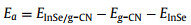
|
(1) |
where EInSe/g-CN, Eg-CN and EInSe are the total energy of the InSe/g-CN heterojunction, g-CN and single-layer InSe, respectively. Ea of H1, H2, H3 and H4 are −2.327, −2.315, −2.283 and −2.321 eV, respectively. The negative value of Ea indicates that the four heterojunctions have systematic energy stability. Meanwhile, more negative value of Ea means the heterojunction is more steady. Consequently, H1 stacking pattern with Ea of −2.327 eV is the most steady among four stacking patterns, and we choose it for the next calculations.
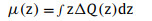
To visualize the charge interaction mechanism between layers of the InSe/g-CN heterojunction, the charge density (Q(z)) and the charge density difference (ΔQ(z)) are calculated to analyze the charge distribution and charge migration. ΔQ(z) is evaluated by using Eq. 2 [31]:

|
(2) |
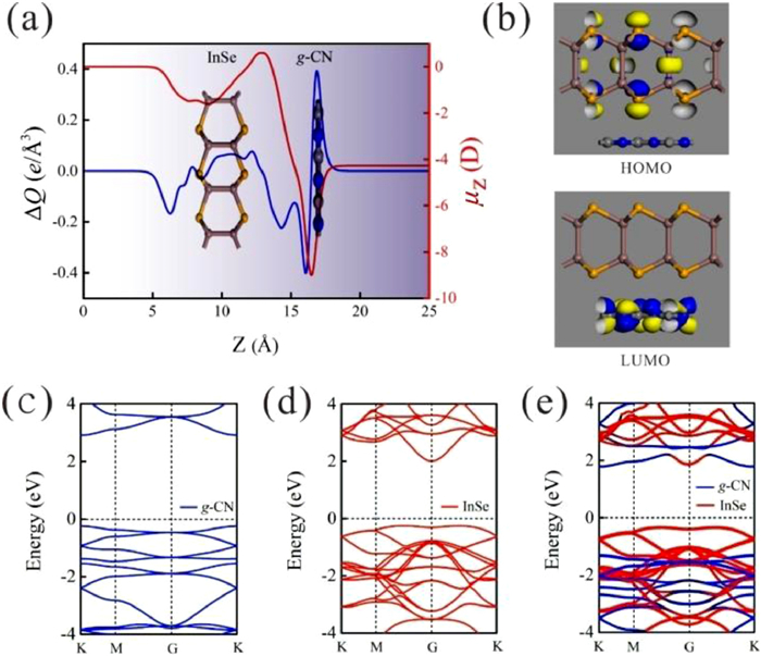
where Q(z)InSe/g-CN, Q(z)g-CN and Q(z)InSe represent Q(z) of the InSe/g-CN heterojunction, g-CN and single-layer InSe, respectively. As shown in Fig. 1a, charges (the charges here refers to electrons) gather in the g-CN layer and dissipate in the InSe layer, indicating that charges are migrated from the InSe layer to the g-CN layer, which is mainly due to the strong electronegativity of the N atoms in the g-CN layer. Similar charge migration and redistribution have also been observed in the other 2D vdW heterojunctions [29]. More importantly, the negatively charged g-CN layer is conducive to the adsorption of the hydrogen ions, and the positively charged InSe layer is conducive to the adsorption of intermediates (OH*, O*, OOH*, HOOH* and O + OH*) during OER. And thus the electrons and holes are effectively segregated, and a built-in electric field is formed, which is conducive to the water splitting of the InSe/g-CN heterojunction. To order to further describe the interfacial electronic properties, the dipole moment μ(z) is also given by using Eq. 3 [31]:
|
(3) |

|
Download:
|
| Fig. 1. (a) Charge density difference (blue line) and interface dipole moment (red line) along the Z-direction for the InSe/g-CN heterojunction; (b) HOMO and LUMO results of the InSe/g-CN heterojunction; (c) Energy band structure of g-CN; (d) Energy band structure of the single-layer InSe; (e) Energy band structure the InSe/g-CN heterojunction. | |
It is found by calculation that there is a μ(z) of −4.27 D from the InSe layer to the g-CN layer, which confirms the formation of an interlayer dipole moment inside the heterojunction.
Meanwhile, to gain further detailed of electronic properties, the highest occupied molecular orbital (HOMO) and the lowest unoccupied molecular orbital (LUMO) orbital distribution of the InSe/g-CN heterojunction are calculated. According to the positions occupied by the orbitals, the heterojunctions can be divided into two categories: When HOMO and LUMO are located in the same layer of the heterojunction, the heterojunction is labeled as type-Ⅰ heterojunction. When HOMO and LUMO are located in two different layers of the heterojunction, the heterojunction is labeled as type-Ⅱ heterojunction [47]. Compared with the type-Ⅰ heterojunctions, the most notable feature of the type-Ⅱ heterojunction is the separation of the electrons and holes near the interface in the self-consistent quantum well. Fortunately, as shown in Fig. 1b, the InSe/g-CN heterojunction belongs to type-Ⅱ heterojunction, where HOMO and LUMO are located in the single-layer InSe and g-CN, respectively. Therefore, as a kind of type-Ⅱ semiconductor, the InSe/g-CN heterojunction has successfully achieved the separation of the electrons and holes, which meets an important requirement for photolysis water.
Then, the energy band structures of g-CN, the single-layer InSe and InSe/g-CN heterojunction are calculated at the HSE06 level, as shown in Figs. 1c–e. It can be seen that both the conduction band minimum (CBM) and the valence band maximum (VBM) of g-CN reside at the K point. Therefore, g-CN is a direct bandgap semiconductor, and the value of Eg is 3.16 eV. CBM of the single-layer InSe reside at the G point, and VBM of the single-layer InSe reside between the M and G points. Therefore, the single-layer InSe is an indirect bandgap semiconductor, and the value of Eg is 2.25 eV. These results agree well with those previous reported [31, 33]. After the formation of the InSe/g-CN heterojunction, CBM of the InSe/g-CN heterojunction reside at the K point, and VBM of the InSe/g-CN heterojunction reside between the M and G points. Therefore, the InSe/g-CN heterojunction is an indirect bandgap semiconductor, and the value of Eg is 2.13 eV, which is in the energy range of visible light (1.6–3.2 eV), so the valence electrons can accept adequate energy given by visible light to complete the transition, yielding the electrons in the conduction bands and holes in the valence bands. Meanwhile, we can see that CBM and VBM of the InSe/g-CN heterojunction are contributed by the g-CN layer and the InSe layer, respectively, which proves again that the electrons and holes are segregated and the InSe/g-CN heterojunction is indeed a type-Ⅱ heterojunction.
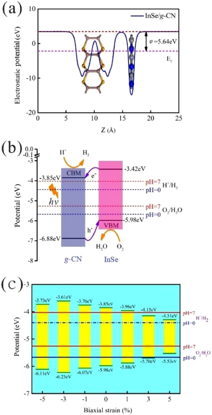
Moreover, in order to quantify the band alignments of the InSe/g-CN heterojunction, we need to determine the potentials of the band-edge positions. Firstly, the electrostatic potentials of the InSe/g-CN heterojunction is calculated, as shown in Fig. 2a. Then, the work function (φ) of the InSe/g-CN heterojunction is also calculated, which is gained by using Eq. 4 [15]:

|
(4) |

|
Download:
|
| Fig. 2. (a) Electrostatic potential of the InSe/g-CN heterojunction. The red and pink dashed lines denote the fermi level and the vacuum energy level, respectively; (b) Potentials of band-edge positions for the InSe/g-CN heterojunction; (c) Potentials of band-edge positions at biaxial strains of −5%, −3%, −1%, 1%, 3% and 5%. | |
where Evac and Ef are the electrostatic potential at the vacuum nearby the surface and the electrostatic potential at the Fermi level, respectively. Evac, Ef and φ of the InSe/g-CN heterojunction are 3.47, −2.17 and 5.64 eV, respectively. Meanwhile, the standard hydrogen potential (EH + /H2) can be obtained by EH + /H2= −4.44 eV + pH × 0.059 eV, and the standard oxygen potential (EO2/H2O) can be obtained by EO2/H2O= −5.67 eV + pH × 0.059 eV [48, 49]. Then, based on φ and the relative positions of CBM, VBM and the Fermi level, the potential of CBM (Ec) and the potential of VBM (Ev) for the InSe/g-CN heterojunction are obtained, as shown in Fig. 2b. Theoretically, to satisfy the requirements for the photolysis water, Ec of the photocatalysts should be higher than EH + /H2 (when pH = 0, EH + /H2 = −4.44 eV; when pH = 7, EH + /H2 = −4.03 eV) and Ev of the photocatalysts should be lower than EO2/H2O (when pH = 0, EO2/H2O = −5.67 eV; when pH = 7, EO2/H2O = −5.26 eV) [50]. The value of Ec for the InSe/g-CN heterojunction is −3.85 eV, which is 0.18 eV higher than EH + /H2 at pH = 7. The value of Ev for the InSe/g-CN heterojunction is −5.98 eV, which is 0.72 eV lower than EO2/H2O at pH = 7. The electrons excited by light are migrated from the InSe layer to the g-CN layer, which leads to forms an internal electric field from the InSe layer to the g-CN layer. Here, although the built-in electric field promotes the recombination of the carriers, the photons stimulate the continuous generation of the carriers. The above two processes maintain a balance, which makes this built-in electric field stable. Then, similar to the principle of electrolyzing water, the InSe/g-CN heterojunction relies on this built-in electric field to split water. The g-CN layer is the cathode of the built-in electric field, where HER occurs. And the InSe layer is the anode of the built-in electric field, where OER occurs. Therefore, it is concluded that the InSe/g-CN heterojunction satisfy the requirements for photolysis water in terms of potential.
Furthermore, the InSe/g-CN heterojunction is applied biaxial strain from −5% to +5% to explore the effect of strain on the Eg. In Fig. S3 (Supporting information), when the values of biaxial strain applied are −5%, −3%, −1%, 1%, 3% and 5%, Eg of the InSe/g-CN heterojunction are 2.38, 2.62, 2.31, 1.92, 1.55 and 1.22 eV, respectively. It is found that Eg increases first and then declines with the decline of biaxial strain, and Eg declines with the increase of biaxial strain. Then, the potentials of band-edge positions under different biaxial strain conditions are calculated, as shown in Fig. 2c. Theoretically, the optimal Eg for photolysis water is between 2.0 eV and 2.2 eV. If Eg is too large, the utilization of visible light will be reduced, while if Eg is too small, the potential driving force of the water splitting reaction will be insufficient, and it will not even be able to provide adequate energy to make the valence electrons transition to CB. Therefore, when −5%, −3% and −1% biaxial strain are applied, the utilization of visible light will be reduced. When 1% biaxial strain is applied, the potential driving force that can be provided to HER is too small. When 3% and 5% biaxial strain are applied, Ec and Ev could not satisfy the requirements for photolysis water. Therefore, under the condition of not applying any strain, the effect of the InSe/g-CN heterojunction for photolysis water is the most ideal.
In order to further explore whether the water splitting reaction can implement spontaneously driven by visible light, we need to judge the thermodynamic sustainability of water splitting reaction by calculating ΔG of each state in the HER and OER process. HER is divided into 2 steps (Eq. 5) [51]:
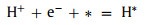
|
(5a) |
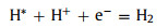
|
(5b) |
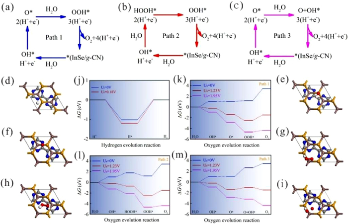
For OER, there are 3 paths [52]. As shown in Figs. 3a–c, path 1, path 2 and path 3 all contain 4 steps. Here, * represents the InSe/g-CN heterojunction substrate. OH*, O*, OOH*, HOOH* and O + OH* represent that OH, O, OOH, HOOH and O + OH are adsorbed on the substrate, respectively. ΔG is calculated by using Eq. 6 [53]:

|
(6) |

|
Download:
|
| Fig. 3. (a–c) Three oxygen evolution reaction (OER) paths; (d) Optimized geometries of H on the InSe/g-CN heterojunction during HER; (e–i) Optimized geometries of OH, O, OOH, HOOH and O + OH on the InSe/g-CN heterojunction during OER; (g) ΔG of HER at pH = 7 and at different potential differences (0 and 0.18 V); (k) ΔG of OER for path 1 at pH = 7 and at different potential differences (0, 1.23 and 1.95 V); (l) ΔG of OER for path 2 at pH = 7 and at different potential differences (0, 1.23 and 1.95 V); (m) ΔG of OER for path 3 at pH = 7 and at different potential differences (0, 1.23 and 1.95 V). | |
where ΔE is the variation of total energy. ΔZPE is the variation of zero point energy. T is the temperature (298 K), and ΔS is the variation of entropic contribution. ΔGU = −eU, where e is the electron charge and U is the potential difference. ΔGpH = −kBTln10 × pH, where kB is the Boltzmann's constant, and here, pH = 7 is considered. More detailed, ZPE could be calculated by using Eq. 7:
|
(7) |
Subsequently, TS could be evaluated using Eq. 8:
|
(8) |
where h and v represent Planck's constant and the vibrational frequency, respectively. Figs. 3d–i show the lowest system energy adsorption sites of H, OH, O, OOH, HOOH and O+OH on the InSe/g-CN heterojunction, respectively. The potential driving force for HER (Ue) could be obtained by Ec − EH + /H2. Here, when pH = 7, Ue = 0.18 eV. And the potential driving force for OER (Uh) can be obtained by EH + /H2 − Ev. Here, when pH = 7, Uh = 1.95 eV. According to the Sabatier principle [54], a good HER catalyst should be able to form a strong enough bond with the H atom in the first step of HER to promote the proton-electron migration process, and it should be beneficial to bond breakage and the release of H2 in the second step of HER. Therefore, the most ideal result is that ΔG in the first step of HER should be less than 0 eV and close to 0 eV. As shown in Fig. 3j, for HER, when Ue = 0 V or 0.18 V, ΔG decreases to −1.02 eV and −1.20 eV, (less than 0 eV and close to 0 eV), respectively, which proves that HER can implement spontaneously and the release of hydrogen gas is relatively easy. In Fig. 3k, for path 1 of OER, when Uh = 0 V, ΔG increases each step to 3.44 eV eventually; when Uh = 1.23 V (theoretical minimum potential driving force required for OER) or Uh = 1.95 V, ΔG increases in the fourth reaction. In Fig. 3l, for path 2 of OER, when 1.23 V or 1.95 V, ΔG also increases in the fourth reaction. Therefore, for paths 1 and 2, the water splitting reaction cannot implement spontaneously. Meanwhile, the most difficult step is the release of oxygen in the fourth step (OOH* + 3(H+ + e−) → O2 + 4(H+ + e−) + *), which requires a greater potential driving force. In Fig. 3m, for path 3 of OER, when 1.23 V, ΔG increase in the third reaction. Excitingly, when Uh = 1.95 V, ΔG declines each step of OER, which implies that when the InSe/g-CN heterojunction is used as the photocatalyst, OER become feasible in thermodynamics. Meanwhile, the most difficult step is the third step reaction (O* + 2(H+ + e−) + H2O → O + OH* + 3(H+ + e−)), and this step determines the rate of entire OER. Therefore, it is concluded that the photogenerated carriers of the InSe/g-CN heterojunction can provide sufficient potential driving force to stimulate HER and OER processes without any other sacrificial reagents or promoters.
As the photocatalysts for water splitting, optical properties are also particularly important, particularly the capability to use the visible light, because the energy of visible light accounts for 40% of the total energy of solar. To calculate the optical properties the InSe/g-CN heterojunction including real part of dielectric function (ε1(ω)), imaginary part of dielectric function (ε2(ω)), absorption coefficient (α(ω)) and reflectivity (R(ω)), the GW + BSE approach is used. The calculated results of ε1(ω) and ε2(ω) are shown in Figs. 4a and b. The α(ω) and R(ω) can be determined by using Eqs. (9) and (10) [55]:

|
(9) |
|
(10) |

|
Download:
|
| Fig. 4. (a) The real part ε1(ω) of dielectric function; (b) The imaginary part ε2(ω) of dielectric function; (c) Absorption coefficient α(ω); (d) Reflectivity R(ω). | |
where ω is the frequency of electromagnetic waves. As shown in Fig. 4c, there are several peaks for α(ω) of the InSe/g-CN heterojunction. The photon energy corresponding to the absorption peaks are 1.2, 2.2, 2.8, 3.2 and 3.6 eV, respectively. And in the blue and violet light regions, the value of α(ω) is larger than other visible light regions. The energy corresponding to blue and violet light is 3.0 eV, while Eg of the InSe/g-CN heterojunction is 2.13 eV, which means that the photons can provide adequate energy to facilitate the electrons to migrate from VB to CB. Unfortunately, in Fig. 4d, it can be seen that R(ω) is also relatively large in the blue and violet regions, which has a certain adverse effect on the InSe/g-CN heterojunction for photolysis water.
Meanwhile, ηS is an important indicator to evaluate the catalytic efficiency of the photocatalysts [56]. ηS of the photocatalysts can be calculated roughly by using Eq. 11 [57]:

|
(11) |
where ΔG = 1.23 eV, E is the minimum photon energy required to make an electron jump from VB to CB. Here, E = Eg. I(ħω) is the spectral irradiance of the AM1.5 solar spectrum when the photon energy is equal to ħω. According to the above formula, calculated ηS of the InSe/g-CN heterojunction is 13.7%, which is a relatively high value compared to the other water splitting photocatalysts [58]. Therefore, it is economically viable to use the InSe/g-CN heterojunction as the photocatalyst to split water.
In summary, according to the different stacking patterns of g-CN and the single-layer InSe, we have constructed four InSe/g-CN heterojunctions, labeled as H1, H2, H3 and H4. Then, H1 stacking pattern (Ea = −2.327 eV) with the smallest Ea is selected for the subsequent calculations. The results show that the InSe/g-CN heterojunction is a type-Ⅱ semiconductor with Eg of 2.13 eV, whose HOMO and LUMO are separately contributed by the g-CN layer and InSe layer, respectively. Ec and Ev are −3.85 eV and −5.98 eV, respectively, which meet the requirements for photolysis water. Meanwhile, when pH = 7, HER and OER can implement spontaneously under visible light irradiation without the need for sacrificial reagents and promoters, which verifies the thermodynamic sustainability of photolysis water. Besides, the InSe/g-CN heterojunction mainly absorbs blue and violet light, and its ηS is 13.7%. In short, these results indicate that the InSe/g-CN heterojunction is a kind of outstanding photocatalyst for water splitting, and it has very broad commercial application prospects.
Declaration of competing interestThe authors declare that they have no known competing financial interests or personal relationships that could have appeared to influence the work reported in this paper.
AcknowledgmentsThe authors acknowledge supports by National Natural Science Foundation of China (NSFC, Nos. 51471124, U1766216), National Key R & D Program of China (No. 2018YFB0905600) and Natural Science Foundation of Shaanxi province, China (Nos. 2019JM-189, 2020JM-218). The authors also acknowledge supported by HPC Platform, Xi'an Jiaotong University.
Appendix A. Supplementary dataSupplementary material associated with this article can be found, in the online version, at doi:10.1016/j.cclet.2021.07.010.
| [1] |
L.Y. Han, Nature 567 (2019) 465-467. DOI:10.1038/d41586-019-00936-x |
| [2] |
I.E.M. de Graaf, T. Gleeson, L.P.H. van Beek, E.H. Sutanudjaja, M.F.P. Bierkens, Nature 574 (2019) 90-94. DOI:10.1038/s41586-019-1594-4 |
| [3] |
S.J. Guo, Y. Yu, Q. Zhang, Chin. Chem. Lett. 28 (2017) 2169-2170. DOI:10.1016/j.cclet.2017.11.047 |
| [4] |
H.J. Le, D.V. Dao, Y.T. Yu, J. Mater. Chem. A 8 (2020) 12968-12974. DOI:10.1039/d0ta03552a |
| [5] |
S. Toghyani, E. Baniasadi, E. Afshari, N. Javani, Int. J. Hydrogen Energy 45 (2020) 34993-35005. DOI:10.1016/j.ijhydene.2020.01.232 |
| [6] |
K. Chen, S.F. Deng, Y. Lu, et al., Chin. Chem. Lett. 32 (2021) 765-769. DOI:10.1016/j.cclet.2020.05.030 |
| [7] |
N. Ullah, S.W. Chen, Y.L. Zhao, R.Q. Zhang, J. Phys. Chem. Lett. 10 (2019) 4310-4316. DOI:10.1021/acs.jpclett.9b01248 |
| [8] |
Y.X. Wang, F.T. He, L. Chen, et al., Chin. Chem. Lett. 31 (2020) 2668-2672. DOI:10.1016/j.cclet.2020.08.003 |
| [9] |
S.J. Sun, H. Ding, L.F. Mei, Y. Chen, Q. Hao, et al., Chin. Chem. Lett. 31 (2020) 2287-2294. DOI:10.1016/j.cclet.2020.03.026 |
| [10] |
T. Soltani, B.K. Lee, Sci. Total Environ. 736 (2020) 10. |
| [11] |
G.J. Wei, K. Du, X.X. Zhao, et al., Chin. Chem. Lett. 31 (2020) 2641-2644. DOI:10.1016/j.cclet.2020.02.029 |
| [12] |
F.H. Mu, B.L. Dai, W. Zhao, et al., Chin. Chem. Lett. 31 (2020) 1773-1781. DOI:10.1016/j.cclet.2019.12.015 |
| [13] |
F. Yu, L.C. Wang, Q.J. Xing, et al., Chin. Chem. Lett. 31 (2020) 1648-1653. DOI:10.1016/j.cclet.2019.08.020 |
| [14] |
F. Wang, Z.G. Kan, F. Cao, et al., Chin. Chem. Lett. 29 (2018) 1417-1420. DOI:10.1016/j.cclet.2017.11.030 |
| [15] |
C. He, F.S. Han, J.H. Zhang, W.X. Zhang, J. Mater. Chem. C 8 (2020) 6923-6930. DOI:10.1039/d0tc00852d |
| [16] |
J. Ji, X.F. Hu, R.B. Tian, et al., J. Mater. Chem. C 8 (2020) 2927-2936. DOI:10.1039/c9tc06530j |
| [17] |
N. Zhang, L.M. Yan, Y. Lu, et al., Chin. Chem. Lett. 31 (2020) 2071-2076. DOI:10.1016/j.cclet.2019.12.014 |
| [18] |
M.F.C. Andrade, H.Y. Ko, R. Car, A. Selloni, J. Phys. Chem. Lett. 9 (2018) 6716-6721. DOI:10.1021/acs.jpclett.8b03103 |
| [19] |
S.J. Hu, Y.J. Yu, Y. Guan, et al., Chin. Chem. Lett. 31 (2020) 2839-2842. DOI:10.1016/j.cclet.2020.08.021 |
| [20] |
S.M. Sun, J. Wu, M. Watanabe, T. Akbay, T. Ishihara, J. Phys. Chem. Lett. 10 (2019) 2998-3005. DOI:10.1021/acs.jpclett.9b01032 |
| [21] |
Y.T. Li, Z.F. Liu, J.W. Li, M.N. Ruan, Z.G. Guo, J. Mater. Chem. A 8 (2020) 6256-6267. DOI:10.1039/d0ta00452a |
| [22] |
M.W. Kim, B. Joshi, E. Samuel, et al., Appl. Catal. B: Environ. 271 (2020) 11. |
| [23] |
N. Faisal, Biointerface Res. Appl. Chem. 10 (2020) 7223-7233. DOI:10.33263/BRIAC106.72237233 |
| [24] |
G.L. Liu, J.H. Zhou, W.N. Zhao, Z.M. Ao, T.C. An, Chin. Chem. Lett. 31 (2020) 1966-1969. DOI:10.1016/j.cclet.2019.12.023 |
| [25] |
S. Poorahong, R. Izquierdo, M. Siaj, J. Mater. Chem. A 5 (2017) 20993-21001. DOI:10.1039/C7TA05826H |
| [26] |
N.S. Liu, J.F. Zhang, S. Zhou, J.J. Zhao, J. Mater. Chem. C 8 (2020) 6264-6272. DOI:10.1039/d0tc00062k |
| [27] |
M. Yousefi, H. Eshghi, M. Karimi-Nazarabad, A. Farhadipour, New J. Chem. 44 (2020) 20470-20478. DOI:10.1039/d0nj04572a |
| [28] |
F. Opoku, P.P. Govender, Appl. Surf. Sci. 525 (2020) 12. |
| [29] |
Z. Xue, X.Y. Zhang, J.Q. Qin, R.P. Liu, Appl. Surf. Sci. 510 (2020) 7. |
| [30] |
H. Wang, W. Wei, F.P. Li, B.B. Huang, Y. Dai, Phys. Chem. Chem. Phys. 21 (2019) 8856-8864. DOI:10.1039/c9cp01196j |
| [31] |
C. He, J.H. Zhang, W.X. Zhang, T.T. Li, J. Phys. Chem. Lett. 10 (2019) 3122-3128. DOI:10.1021/acs.jpclett.9b00909 |
| [32] |
H. Li, C.B. Cao, H.W. Hao, et al., Diam. Relat. Mat. 15 (2006) 1593-1600. DOI:10.1016/j.diamond.2006.01.013 |
| [33] |
X.S. Lv, W. Wei, F.P. Li, B.B. Huang, Y. Dai, Nano Lett. 19 (2019) 6391-6399. DOI:10.1021/acs.nanolett.9b02572 |
| [34] |
K. Srinivasu, S.K. Ghosh, J. Mater. Chem. A 3 (2015) 23011-23016. DOI:10.1039/C5TA04955E |
| [35] |
D.M. Liang, T. Jing, Y.C. Ma, et al., J. Phys. Chem. C 120 (2016) 24023-24029. DOI:10.1021/acs.jpcc.6b08699 |
| [36] |
L.J. Sham, W. Kohn, Phys. Rev. 145 (1966) 561. DOI:10.1103/PhysRev.145.561 |
| [37] |
G.R. Su, S. Yang, S. Li, et al., J. Am. Chem. Soc. 141 (2019) 1628-1635. DOI:10.1021/jacs.8b11459 |
| [38] |
J.P. Perdew, K. Burke, M. Ernzerhof, Phys. Rev. Lett. 77 (1996) 3865-3868. DOI:10.1103/PhysRevLett.77.3865 |
| [39] |
S. Grimme, J. Comput. Chem. 27 (2006) 1787-1799. DOI:10.1002/jcc.20495 |
| [40] |
J. Heyd, G.E. Scuseria, M. Ernzerhof, J. Chem. Phys. 118 (2003) 8207-8215. DOI:10.1063/1.1564060 |
| [41] |
P. Umari, G. Stenuit, S. Baroni, Phys. Rev. B 79 (2009) 4. |
| [42] |
E.E. Salpeter, H.A. Bethe, Phys. Rev. 84 (1951) 1232-1242. DOI:10.1103/PhysRev.84.1232 |
| [43] |
J.A. Greathouse, P.F. Weck, M.E. Gordon, E. Kim, C.R. Bryan, J. Phys. Condes. Matter. 32 (2020) 8. |
| [44] |
F. Ding, A. Rosen, K. Bolton, Phys. Rev. B 70 (2004) 6. |
| [45] |
D. Sidler, S. Riniker, Phys. Chem. Chem. Phys. 21 (2019) 6059-6070. DOI:10.1039/c8cp06800c |
| [46] |
C. He, J.H. Zhang, W.X. Zhang, T.T. Li, J. Phys. Chem. C 123 (2019) 5157-5163. DOI:10.1021/acs.jpcc.8b08909 |
| [47] |
M.M. Dong, C. He, W.X. Zhang, J. Phys. Chem. C 121 (2017) 22040-22048. DOI:10.1021/acs.jpcc.7b05650 |
| [48] |
H.L.L. Zhuang, R.G. Hennig, Chem. Mat. 25 (2013) 3232-3238. DOI:10.1021/cm401661x |
| [49] |
H.C. Yang, J.J. Li, L. Yu, et al., J. Mater. Chem. A 6 (2018) 4161-4166. DOI:10.1039/C7TA10624F |
| [50] |
R.M.N. Yerga, M.C.A. Galvan, F. del Valle, J.A.V. de la Mano, J.L.G. Fierro, ChemSusChem 2 (2009) 471-485. |
| [51] |
K.W. Park, A.M. Kolpak, J. Mater. Chem. A 7 (2019) 6708-6719. DOI:10.1039/c8ta11087e |
| [52] |
S. Lin, X.X. Ye, X.M. Gao, J. Huang, J. Mol. Catal. A: Chem. 406 (2015) 137-144. DOI:10.1016/j.molcata.2015.05.018 |
| [53] |
J. Rossmeisl, A. Logadottir, J.K. Norskov, Chem. Phys. 319 (2005) 178-184. DOI:10.1016/j.chemphys.2005.05.038 |
| [54] |
A.R. Zeradjanin, G. Polymeros, C. Toparli, et al., Phys. Chem. Chem. Phys. 22 (2020) 8768-8780. DOI:10.1039/d0cp01108h |
| [55] |
T.T. Li, C. He, W.X. Zhang, Appl. Surf. Sci. 441 (2018) 77-84. DOI:10.1016/j.apsusc.2018.01.218 |
| [56] |
K. Ren, W. Tang, M. Sun, et al., Nanoscale 12 (2020) 17281-17289. DOI:10.1039/d0nr02286a |
| [57] |
C.F. Fu, J.Y. Sun, Q.Q. Luo, et al., Nano Lett. 18 (2018) 6312-6317. DOI:10.1021/acs.nanolett.8b02561 |
| [58] |
C.F. Fu, C.Y. Zhao, Q.J. Zheng, et al., Sci. China Chem. 63 (2020) 1134-1141. DOI:10.1007/s11426-020-9766-5 |