 2022, Vol. 33


b Hubei Key Laboratory of Low Dimensional Optoelectronic Materials and Devices, Hubei University of Arts and Science, Xiangyang 441053, China;
c Institute of Mathematics, Free University of Berlin, Arnimallee 6, D-14195 Berlin, Germany
Ammonia (NH3) is one of the most important building blocks for chemicals, such as fertilizer, explosives, and hydrogen carriers [1, 2]. Industrial ammonia is produced by Haber-Bosch process under high temperature and high pressure conditions (300–500 ℃ and 150–300 atm), consuming 1%–2% of the total global energy and releasing millions of tons of CO2 [3]. Developing an environmentally friendly method under mild conditions is a great challenge to replace Haber-Bosch production of NH3 [4]. Up to date, solar-driven nitrogen reduction reaction (NRR) appears to be the most promising way due to the superiority with environmentally benign, low-energy consuming and sustainability [5]. The great challenge of photocatalytic NRR is effectively activating N2 molecule with photogenerated electron transferring to the anti-binding orbitals of N2 molecule, which requires the photocatalyst chemically adsorbing N2 for effective activation of the inert triple bonds [6]. N2 can be activated by back-donation process. The lone-pair electrons of N2 would transfer to the empty orbitals of activated sites, while the d or p electrons of activate sites can be donated into the anti-binding states of N2 [7, 8]. Tremendous experimental efforts have been taken to evaluate the performance of different catalysts, such as metal alloys [9], oxide [10], nitride [11], MOF [6, 12], ZIF [13], perovskites [14]. Thanks to the development of single atom catalyst (SAC), some SACs have been expected to have superior catalytic performance for NRR [7, 15-18]. Rational design of NRR SAC is drawing more and more attention recently.
Experimental design of NRR SAC is far from satisfactory and of high-cost. Density functional theory (DFT) calculations have been chosen as a convenient and low-cost approach for catalyst performance evaluation [19-22]. More importantly, DFT provides deep insights into reaction mechanism at the atomic level [23-28]. A promising NRR SAC has several prerequisites, such as thermodynamic and dynamic stabilities, the selectivity of NRR respect to hydrogen evolution reaction (HER), the ability to activate the inert NN triple bond [29], and more importantly, the limiting potential for contract the energy barrier of the rate-limiting step [19]. As a general design SAC strategy, substrate materials are decorated by single heteroatom to form SAC, which acts as active site for N2 adsorption and protonation with tunable electronic structures [30, 31].
Bulk BeO is known to have a polar wurtzite structure with high thermal conductivity and hardness [32]. It was claimed that few-layer BeO two-dimensional (2D) sheets with honeycomb structure can be synthesized through a wet chemistry approach [33]. Recently, BeO monolayer is experimentally achievable on Ag(111) thin film by epitaxial growth [34]. Theoretical study predicted that the electronic and magnetic properties of BeO monolayer can be tuned by intrinsic vacancy, transition metal substitutions and ribbon width [35-37]. The optical properties of BeO monolayer has been reported for the heterostructure with germanene [38]. BeO monolayer can also be used as two dimensional field-effect transistors on account of its insulting character [39]. Compared with the bulk catalysts, 2D catalysts has be reported to possess unique electronic structures and photocatalytic properties [40-42]. Inspired by these, we thus wonder whether the BeO monolayer can be used for high efficient NRR catalyst. In this work, we rationally designed an excellent photocatalyst with thermodynamic stability, high activity and selectivity for NRR through single transition metal (TM) atom (TM = Sc, Ti, V, Cr, Mn, Fe, CO, Ni, Cu, Zn, Y, Zr, Nb, Mo, Ru, Rh, Pd, Ag and Cd) supported by BeO monolayer by using spin-polarized density functional theory.
All calculations were performed by using the Vienna ab initio Simulation Package (VASP) [43]. The projected augmented wave pseudopotential method with a cutoff energy of 500 eV for plane-wave basis was set to treat the electron-ion interactions [44]. All atomic structures were fully relaxed geometry optimization with a converging tolerance of 0.02 eV/Å for residual force and 10−6 eV for energy. The van der Waals (vdW) interactions were described by the semi-empirical DFT-D3 method [45]. A vacuum space in the z-direction was set to 20 Å for preventing the interaction between periodic images. All catalysts are modeled by single TM atoms substituting one Be in BeO supercells (4 × 4 × 1). The Brillouin Zone was sampled with the Gamma centered mesh with a 3 × 3 × 1 k-point grid for geometry relaxation and a 5 × 5 × 1 k-point grid for electron structure analysis. And the band structures and optical absorption spectra were calculated by HSE06 method. The dynamical stability of SACs were confirmed by ab initio molecular dynamics (AIMD) simulations in canonical ensemble with the Nose-Hoover thermostat.
In order to investigate NRR process, six steps of coupled proton and electron transfer (CPET) are considered and the computational hydrogen electrode (CHE) model is employed in free energy profiles for reduction reaction, where the free energy of H+ + e− is replaced by one-half of the chemical potential of the hydrogen molecule [46]. The reaction Gibbs free energy of each elementary step is calculated by the following equation: ΔG = ΔE + ΔZPE - TΔS, where ΔE is the reaction energy, ΔZPE is the difference of zero point energy and ΔS is the difference of reaction entropy between the product and reactant of each elementary step, respectively. T is the absolute temperature. The entropy contribution of each gas phase species is obtained from NIST database [47]. The optical absorption spectra is calculated based on the complex dielectric function [48].
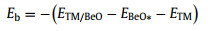
As shown in Fig. 1a, a series of TM atoms (TM = Sc, Ti, V, Cr, Mn, Fe, Co, Ni, Cu, Zn, Y, Zr, Nb, Mo, Ru, Rh, Pd, Ag and Cd) supported by BeO monolayer are screened as candidates for NRR. Binding energy (Eb) and cohesive energy (Ec) are calculated to determine the stability of SACs:
|
(1) |
|
(2) |

|
Download:
|
| Fig. 1. (a) Schematic view of single TM anchoring in BeO monolayer. Lime, red and blue violet balls represent Be, O and TM atoms, respectively. (b) Difference between binding energy of single TM atom anchoring on BeO monolayer with a Be vacancy and cohesive energy of isolate TM atoms aggregating metal clusters. (c) Variations of energy and temperature versus the AIMD simulation time for Ru/BeO, and the insets denote the top and side view of Ru/BeO after AIMD simulation last for 5 ps at T = 500 K. | |
where ETM/BeO, EBeO*, ETM and ETMb represent the energy of a TM atom anchored on Be vacancy, the energy of BeO monolayer with a Be vacancy, the energy of an isolated single TM atom in vacuum, and the energy of a TM atom in the bulk crystal unit cell, respectively.
The anchoring single TM atom on BeO monolayer is thermodynamically favorable than diffusion and aggregation once Eb – Ec > 0. As shown in Fig. 1b, all SACs are stable. All calculated values are list in Table S1 (Supporting information). Moreover, the thermal stability of Ru/BeO is further evaluated by AIMD simulation. Our results show that Ru/BeO is the best NRR catalyst among these 19 SACs. As shown in Fig. 1c, during the AIMD equilibration, both the energy and temperature of Ru/BeO monolayer only oscillate within small ranges and there is no significant structure distortion at an elevated temperature of 500 K. The thermodynamical and dynamical stabilities of the Ru/BeO SAC meet the prerequisite as a promising NRR candidate.
N2 adsorption is the first process for NRR and effective activation of N2 is vital for further protonation. As shown in Fig. S1 (Supporting information), the interaction between N2 and BeO monolayer is physical adsorption with adsorption energy around −0.10 eV. Besides, the distance between N and active site (Be or O) varies in the range of 2.93~3.33 Å, which is larger than covalent N-Be (1.73 Å) and N-O (1.34 Å) bond lengths based on covalent radii [49]. The bond length of N≡N is 1.11 Å, which is equal to free N2 molecular in our calculation. Therefore, N2 can not be effectively activated by pure BeO monolayer and that SACs consist of single TM atoms and BeO monolayer are considered for further study.
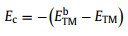
In order to make clear whether NRR or HER would dominate the reaction, the adsorption Gibbs free energies of H and N2 with end-on and side-on pattern on SACs are calculated to evaluate the competitive adsorption between H2 and N2. As shown in Fig. 2a and Table S2 (Supporting information), 7 of 19 SACs are ruled out because these SACs neither adsorb H nor N2, namely, Fe/BeO, Ni/BeO, Cu/BeO, Zn/BeO, Pd/BeO, Ag/BeO, and Cd/BeO. H is the most favorable species on 4 SACs, that is Sc/BeO, V/BeO, Cr/BeO and Y/BeO, implying HER will dominate the reaction on these SACs. For the rest 8 SACs, Ti/BeO, Mn/BeO, Co/BeO and Rh/BeO prefer to adsorb N2 with end-on pattern, and Zr/BeO, Nb/BeO, Mo/BeO and Ru/BeO prefer to side-on pattern, while both patterns would take place on Ti/BeO, Mn/BeO, Zr/BeO, Mo/BeO, and Ru/BeO. And the selectivity of HER/NRR (Table S3 in Supporting information) can be calculated by assuming that the occupation of SAC follows Boltzmann distribution:
|
(3) |

|
Download:
|
| Fig. 2. (a) The histogram of adsorption Gibbs free energies of H and N2 with end-on and side-on pattern on SACs. (b) The Gibbs free energies of the first and last protonation reaction. The horizontal dashed line denotes the selective criteria of 0.65 eV [50, 51]. Blue, orange and green bars represent H adsorption, N2 with end-on pattern and N2 with side-on pattern, respectively. | |
where ΔGi is the adsorption Gibbs free energy of H and N2 with end-on and side-on adsorption configurations, k is Boltzmann constant, and T is the reaction temperature of 298.15 K. So 8 SACs will be assessed in detail for protonation in the following parts.
The first and last protonation step of these 8 SACs, i.e., hydrogenation of *N2 into *N2H, *NH2 into *NH3, is shown in Fig. 2b. The first protonation step involves breaking the strong N≡N triple bond of the N2 molecule, which can be uphill or downhill step determined by different active sites [21, 50]. For these 8 SACs, most of the first protonation steps are uphill, except for *N2(e) into *N2H on Mo/BeO. Previous studies show that 0.65 eV is the criteria for initial screening protonation step [50, 51]. The systems with ΔGN2→N2H > 0.65 eV are ruled out, including Mn/BeO, Co/BeO, and Rh/BeO, for the end-on adsorption configuration and Mn/BeO, Nb/BeO and Ru/BeO for the side-on adsorption configuration.
In the last protonation step of NRR, the adsorption intermediate of *NH2 is much more stable than *NH3 because the sp3 hybrid orbitals of NH3 molecule are fully filled, while sp3 hybrid orbital is half-filled in NH2 [52]. This step would consume extra energy to facilitate protonation of *NH2. We rule out the systems with ΔGN2H→N3H > 0.65 eV and then only Ru/BeO system for end-on adsorption is left for further study.
In order to assess the catalytic performance of Ru/BeO for the reduction of N2 into NH3 in detail, four typical mechanisms with all possible reaction intermediates are taken into consideration, i.e., distal, alternating, mixed and enzymatic (Fig. S2 in Supporting information) [53]. For end-on configuration, N2 can be hydrogenated to NH3 via three different ways, distal, alternating and mixed mechanisms. For side-on configuration, N2 is protonated by proton-electron pairs alternately and two NH3 molecules are released in succession.
Free energy diagrams of Ru/BeO monolayer are illustrated in Fig. 3. The free energy change for first hydrogenation of N2 is significantly reduced compared to previous studies, with a free energy uphill of 0.41 eV and 0.69 eV for end-on and side-on adsorption, respectively. Previous studies show that the first protonation steps on Ru-based catalysts, such as Ru (0001) surface, Ru1-N3 and Ru1-N4 consume 1.08, 0.73 and 0.77 eV energy [54, 55]. For the subsequent elementary steps through distal pathway in Fig. 3a, the intermediate of *NNH could be hydrogenated to *NNH2 with slight large free energy of 0.24 eV. The first NH3 will be released into surroundings and *N remains on Ru/BeO accompany by the free energy downhill by 1.39 eV. The remaining *N would be protonated in the subsequent steps to form *NH, *NH2 and *NH3, with free energy changes of 0.27, −0.47 and 0.18 eV, respectively. And the potential determining step of distal mechanism is the fourth protonation elementary step (*N + H+ + e− = *NH). Finally, the second NH3 will be released from Ru/BeO with 2.08 eV energy demanding, while this process does not involve hydrogenation. The produced NH3 would be dissolved to NH4+ in solution releasing energy, which can promote *NH3 desorption [20, 22, 54].

|
Download:
|
| Fig. 3. Free energy diagrams for N2 reducing to NH3 on Ru/BeO via (a) distal, (b) alternating, (c) mixed and (d) enzymatic mechanisms under different applied potentials. Orange shadow represents the limiting rate step. | |
As an alternating pathway, the hydrogenation of *NNH into *NNH2 presents an even higher free energy, leading to a much negative limiting potential (−0.69 V) than the distal mechanism (−0.41 V) in Figs. 3b and c. Limiting potential (UL) is the required potential to overcome the maximum ΔG among the six elementary reactions defined as UL= -ΔGmax/e [19]. Occasionally, N2 can be protonated by a mixed pathway that shifts from distal to alternating. It can be found that the potential determining step of mixed pathway in Fig. 3c is the fourth protonation elementary step (*NHNH2 + H+ + e− = *NH2NH2) and the onset potential is same as distal pathway. With respect to the enzymatic pathway, protonation also occurs alternatively to the two N of N2. As shown in Fig. 3d, the potential determining step is the first hydrogenation step, with an uphill free energy of 0.69 eV, then the subsequent elementary steps are exothermic except for the last two steps. To the best of our knowledge, the limiting potential of Ru/BeO (−0.41 V) is comparable to other catalysis that have been reported, such as −0.20 V of B/g-C3N4, −0.31 V of B@g-CN, and −0.33 V of Ru@g-C3N4 [7, 20, 21].
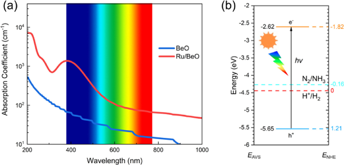
The photoconversion efficiency of Ru/BeO is very important for highly efficient photocatalytic NRR. The band gap of pure BeO monolayer in this work is 5.4 eV in PBE functional and 6.84 eV for HSE06 functional (Fig. S3 in Supporting information), which is corresponding to previous studies with 4.0 eV to 7.4 eV [39, 56-58, 59] and band gap decrease to 1.22 eV and 2.89 eV after Ru doped in BeO monolayer with PBE and HSE06, respectively. As shown in Fig. S4 (Supporting information), the DOS and LDOS indicate that the Ru states are introduced once Ru atom substitution, leading to decrease the band gap. And the introduced peaks near the Fermi level (0 eV) with the energy ranges (−0.50, 0) and (0.85, 1.25) eV, are visualized by LDOS plotted in the Fig. S4b. Pure BeO monolayer leads to less adsorption in the visible light owing to its relatively large band gap. Compared to pure BeO monolayer, the adsorption coefficient in the visible light and infrared (IR) light can be enhanced by Ru/BeO monolayer. As shown in Fig. 4a, the main adsorption peak of BeO monolayer is located at ~200 nm, meaning that pure BeO adsorb most ultraviolet (UV) light and very limited visible light. After single Ru atom decoration, the adsorption coefficient will be enhanced, while adsorption between visible light and infrared light can be greatly enhanced by at least 1 order of magnitude compared to pure BeO monolayer. Therefore, Ru/BeO monolayer with superior optical absorption property maximize utilization of solar energy to drive nitrogen reduction.

|
Download:
|
| Fig. 4. (a) Optical adsorption spectra of pure BeO and Ru/BeO, which are illustrated by the blue and red lines, respectively. (b) Band edge position of Ru/BeO. EAVS and ENHE denote energy levels relative to absolute vacuum scale (AVS) and normal hydrogen electrode (NHE), respectively. | |
As an excellent photocatalyst for NRR, the band edge positions of catalyst should match the N2/NH3 potentials [20, 60]. Fig. 4b displays that the conduction band minimum (CBM) lies above the N2/NH3 potential and the valence band maximum (VBM) is lower than the N2/NH3 potential. The photogenerated electrons on CBM can be transferred to N2 for proton coupled electron process effectively, rather than recombine with the holes on VBM. Thus, the photoexcited electrons and holes would be effectively separated by Ru/BeO, leading to a higher photoconversion efficiency. These results indicate that Ru/BeO a promising photocatalyst for NRR with the merits of suitable visible light absorption and suitable band edge positions.
In summary, based on spin-polarized DFT calculations and CHE model, we rationally designed an efficient photocatalyst Ru/BeO with high thermodynamic stability, high activity and high NRR selectivity. Our results show that Ru/BeO exposes a relatively low limiting potential of −0.41 V for NRR. In addition, as a promising photocatalyst, Ru/BeO shows visible light adsorption and suitable band edge positions. This work is expected to expand the application of 2D BeO monolayer and motivate more research efforts in photocatalysts.
Declaration of competing interestThe authors declare that they have no known competing financial interests or personal relationships that could have appeared to influence the work reported in this paper.
AcknowledgmentsWe acknowledge the financial support from the National Natural Science Foundation of China (NSFC, Nos. 21773309, 21776315), the Fundamental Research Funds for the Central Universities (Nos. 19CX05001A, 20CX05010A), Hubei University of Arts and Science (Nos. 2020kypytd002, 2020kypytd003) and Xiangyang Science and Technology Research and Development (No. 2020YL09).
Supplementary materialsSupplementary material associated with this article can be found, in the online version, at doi:10.1016/j.cclet.2021.06.077.
| [1] |
G. Qing, R. Ghazfar, S.T. Jackowski, et al., Chem. Rev. 120 (2020) 5437-5516. DOI:10.1021/acs.chemrev.9b00659 |
| [2] |
L. Shi, Y. Yin, S. Wang, H. Sun, et al., ACS Catal. 10 (2020) 6870-6899. DOI:10.1021/acscatal.0c01081 |
| [3] |
W. Guo, K. Zhang, Z. Liang, R. Zou, Q. Xu, Chem. Soc. Rev. 48 (2019) 5658-5716. DOI:10.1039/c9cs00159j |
| [4] |
C. Tang, S.Z. Qiao, Chem. Soc. Rev. 48 (2019) 3166-3180. DOI:10.1039/c9cs00280d |
| [5] |
J. Lee, L.L. Tan, S.P. Chai, Nanoscale 13 (2021) 7011-7033. DOI:10.1039/d1nr00783a |
| [6] |
L.W. Chen, Y.C. Hao, Y. Guo, et al., J. Am. Chem. Soc. 143 (2021) 5727-5736. DOI:10.1021/jacs.0c13342 |
| [7] |
C. Ling, X. Niu, Q. Li, A. Du, J. Wang, et al., J. Am. Chem. Soc. 140 (2018) 14161-14168. DOI:10.1021/jacs.8b07472 |
| [8] |
M.A. Légaré, G. Bélanger-Chabot, R.D. Dewhurst, et al., Science 359 (2018) 896-900. DOI:10.1126/science.aaq1684 |
| [9] |
Y. Gong, J. Wu, M. Kitano, et al., Nat. Catal. 1 (2018) 178-185. DOI:10.1038/s41929-017-0022-0 |
| [10] |
R. Guan, D. Wang, Y. Zhang, et al., Appl. Catal. B: Environ. 282 (2021) 119580. DOI:10.1016/j.apcatb.2020.119580 |
| [11] |
T.N. Ye, S.W. Park, Y. Lu, et al., Nature 583 (2020) 391-395. DOI:10.1038/s41586-020-2464-9 |
| [12] |
K.Q. Hu, P.X. Qiu, L.W. Zeng, et al., Angew. Chem. Int. Ed. 59 (2020) 20666-20671. DOI:10.1002/anie.202009630 |
| [13] |
H.K. Lee, C.S.L. Koh, Y.H. Lee, et al., Sci. Adv. 4 (2018) eaar3208. DOI:10.1126/sciadv.aar3208 |
| [14] |
Z. Zhao, D. Wang, R. Gao, et al., Angew. Chem. Int. Ed. 60 (2021) 11910-11918. DOI:10.1002/anie.202100726 |
| [15] |
L. Hui, Y. Xue, H. Yu, et al., J. Am. Chem. Soc. 141 (2019) 10677-10683. DOI:10.1021/jacs.9b03004 |
| [16] |
C. Liu, Q. Li, C. Wu, et al., J. Am. Chem. Soc. 141 (2019) 2884-2888. DOI:10.1021/jacs.8b13165 |
| [17] |
S. Tang, Q. Dang, T. Liu, et al., J. Am. Chem. Soc. 142 (2020) 19308-19315. DOI:10.1021/jacs.0c09527 |
| [18] |
S. Yuan, H. Ren, G. Meng, et al., Appl. Surf. Sci. 555 (2021) 149682. DOI:10.1016/j.apsusc.2021.149682 |
| [19] |
J. Zhao, Z. Chen, J. Am. Chem. Soc. 139 (2017) 12480-12487. DOI:10.1021/jacs.7b05213 |
| [20] |
X. Lv, W. Wei, F. Li, B. Huang, Y. Dai, Nano Lett. 19 (2019) 6391-6399. DOI:10.1021/acs.nanolett.9b02572 |
| [21] |
X. Liu, Y. Jiao, Y. Zheng, et al., J. Am. Chem. Soc. 141 (2019) 9664-9672. DOI:10.1021/jacs.9b03811 |
| [22] |
W. Zhao, L. Zhang, Q. Luo, et al., ACS Catal. 9 (2019) 3419-3425. DOI:10.1021/acscatal.8b05061 |
| [23] |
M. Miao, X. Gong, S. Lei, et al., Chem. Phys. 548 (2021) 111249. DOI:10.1016/j.chemphys.2021.111249 |
| [24] |
L. Zhao, Y. Li, G. Zhou, et al., Chin. Chem. Lett. 32 (2021) 900-905. DOI:10.1016/j.cclet.2020.07.016 |
| [25] |
B. Tian, S. Li, S. Lei, et al., Chin. Chem. Lett. 32 (2021) 2469-2473. DOI:10.1016/j.cclet.2021.02.011 |
| [26] |
W. Song, J. Wang, L. Fu, et al., Chin. Chem. Lett. 32 (2021) 3137-3142. DOI:10.1016/j.cclet.2021.02.043 |
| [27] |
H. Yang, C. He, L. Fu, et al., Chin. Chem. Lett. 32 (2021) 3202-3206. DOI:10.1016/j.cclet.2021.03.038 |
| [28] |
R. Wang, C. He, W. Chen, C. Zhao, J. Huo, Chin. Chem. Lett. (2021) 10.1016/j.cclet.2021.05.024. DOI:10.1016/j.cclet.2021.05.024 |
| [29] |
A.R. Singh, B.A. Rohr, J.A. Schwalbe, et al., ACS Catal. 7 (2017) 706-709. DOI:10.1021/acscatal.6b03035 |
| [30] |
R. Lang, X. Du, Y. Huang, et al., Chem. Rev. 120 (2020) 11986-12043. DOI:10.1021/acs.chemrev.0c00797 |
| [31] |
H.Y. Zhuo, X. Zhang, J.X. Liang, et al., Chem. Rev. 120 (2020) 12315-12341. DOI:10.1021/acs.chemrev.0c00818 |
| [32] |
D. De Faoite, D.J. Browne, F.R. Chang-Díaz, K.T. Stanton, J. Mater. Sci. 47 (2012) 4211-4235. DOI:10.1007/s10853-011-6140-1 |
| [33] |
L. Wang, L. Liu, J. Chen, et al., Angew. Chem. Int. Ed. 59 (2020) 15734-15740. DOI:10.1002/anie.202007244 |
| [34] |
H. Zhang, M. Holbrook, F. Cheng, et al., ACS Nano 15 (2021) 2497-2505. DOI:10.1021/acsnano.0c06596 |
| [35] |
W. Wu, P. Lu, Z. Zhang, W. Guo, ACS Appl. Mater. Interfaces 3 (2011) 4787-4795. DOI:10.1021/am201271j |
| [36] |
N.H. Song, Y.S. Wang, L.Y. Zhang, et al., J. Magn. Magn. Mater. 468 (2018) 252-258. DOI:10.1016/j.jmmm.2018.08.019 |
| [37] |
W. Sukkabot, Chin. J. Phys. 62 (2019) 335-341. DOI:10.1016/j.cjph.2019.10.009 |
| [38] |
X. Chen, X. Sun, J. Jiang, et al., J. Phys. Chem. C 120 (2016) 20350-20356. DOI:10.1021/acs.jpcc.6b06161 |
| [39] |
L. Teitz, M.C. Toroker, Adv. Funct. Mater. 30 (2020) 1808544. DOI:10.1002/adfm.201808544 |
| [40] |
J. Yu, C. He, C. Pu, et al., Chin. Chem. Lett. 32 (2021) 3149-3154. DOI:10.1016/j.cclet.2021.02.046 |
| [41] |
J. Wang, C. He, J. Huo, L. Fu, C. Zhao, Adv. Theory Simulations 4 (2021) 2100003. DOI:10.1002/adts.202100003 |
| [42] |
L. Fu, R. Wang, C. Zhao, et al., Chem. Eng. J. 414 (2021) 128857. DOI:10.1016/j.cej.2021.128857 |
| [43] |
G. Kresse, D. Joubert, Phys. Rev. B 59 (1999) 1758-1775. |
| [44] |
P.E. Blöchl, Phys. Rev. B 50 (1994) 17953-17979. DOI:10.1103/PhysRevB.50.17953 |
| [45] |
S. Grimme, J. Antony, S. Ehrlich, H. Krieg, J. Chem. Phys. 132 (2010) 154104. DOI:10.1063/1.3382344 |
| [46] |
J.K. Nørskov, T. Bligaard, A. Logadottir, et al., J. Electrochem. Soc. 152 (2005) J23. DOI:10.1149/1.1856988 |
| [47] |
Computational Chemistry Comparison and Benchmark Database, https://cccbdb.nist.gov/.
|
| [48] |
M. Gajdoš, K. Hummer, G. Kresse, J. Furthmüller, F. Bechstedt, Phys. Rev. B: Condens. Matter Mater. Phys. 73 (2006) 045112. DOI:10.1103/PhysRevB.73.045112 |
| [49] |
P. Pyykkö, M. Atsumi, Chem. Eur. J. 15 (2009) 186-197. DOI:10.1002/chem.200800987 |
| [50] |
T. He, A.R. Puente Santiago, A. Du, J. Catal. 388 (2020) 77-83. DOI:10.1016/j.jcat.2020.05.009 |
| [51] |
Z. Ma, Z. Cui, C. Xiao, et al., Nanoscale 12 (2020) 1541-1550. DOI:10.1039/c9nr08969a |
| [52] |
C. Ling, Y. Ouyang, Q. Li, et al., Small Methods 3 (2019) 1800376. DOI:10.1002/smtd.201800376 |
| [53] |
H. Liu, L. Wei, F. Liu, et al., ACS Catal. 9 (2019) 5245-5267. DOI:10.1021/acscatal.9b00994 |
| [54] |
E. Skúlason, T. Bligaard, S. Gudmundsdóttir, et al., Phys. Chem. Chem. Phys. 14 (2012) 1235-1245. DOI:10.1039/C1CP22271F |
| [55] |
Z. Geng, Y. Liu, X. Kong, et al., Adv. Mater. 30 (2018) 1803498. DOI:10.1002/adma.201803498 |
| [56] |
Y. Ge, W. Wan, Y. Ren, F. Li, Y. Liu, Appl. Phys. Lett. 117 (2020) 123101. DOI:10.1063/5.0022426 |
| [57] |
W. Zhang, W. Ji, Y. Ma, Mater. Today Commun. 24 (2020) 101344. DOI:10.1016/j.mtcomm.2020.101344 |
| [58] |
C. Xia, W. Li, D. Ma, L. Zhang, Nanotechnology 31 (2020) 375705. DOI:10.1088/1361-6528/ab97d0 |
| [59] |
H. Zheng, X.B. Li, N.K. Chen, et al., Phys. Rev. B: Condens. Matter Mater. Phys. 92 (2015) 115307. DOI:10.1103/PhysRevB.92.115307 |
| [60] |
S. Wang, L. Shi, X. Bai, et al., ACS Cent. Sci. 6 (2020) 1762-1771. DOI:10.1021/acscentsci.0c00552 |