 2022, Vol. 33


b College of Life Science, Fujian Normal University, Fuzhou 350007, China;
c School of Chemistry, Sun Yat-Sen University, Guangzhou 510275, China;
d State Key Laboratory of Structural Chemistry, Fuzhou 350000, China
In 1991, Sony introduced lithium-ion batteries (LIBs) to the market for the first time, which marked the commercialization of rechargeable LIBs [1, 2]. With the rapid development of portable electronic devices, smart grids, and electric vehicles, the energy density of the current LIBs has gradually approached the theoretical limit [3, 4]. Therefore, there is a surging demand for developing high-energy-density batteries, which require high-capacity anodes and cathodes [5]. Compared to commercial LIBs, which normally used graphite as the anode, rechargeable Li metal-based batteries have recently received significant attention. Li metal has been recognized as the "Holy Grail" anode because of its ultrahigh theoretical capacity of 3860 mAh/g and low electrochemical potential of −3.04 V vs. standard hydrogen electrode [6-8]. However, the ultrahigh chemical reactivity and "hostless" nature of metallic Li, as well as the resulting fast capacity decay and safety concerns remain some of the most intractable problems jeopardizing its practical applications [9]. To be specific, Li metal tends to react with the organic liquid, forming the so-called solid electrolyte interphase (SEI) because its chemical potential exceeds the electrochemical window of organic liquid electrolyte. If the SEI is chemically and mechanically stable, it can preclude Li metal from further exposure to the electrolyte. Unfortunately, the dramatic volume change during Li plating/stripping triggers the repeated rupture and growth of the SEI. As a result, the inhomogeneous Li deposition and the continual depletion of Li and electrolyte give rise to low Coulombic efficiency (CE) and potential safety hazards [10-13].
Substantial efforts have been directed to circumventing the above-mentioned issues, including (ⅰ) the exploitation of new electrolytes and the use of solid electrolytes to stabilize the SEI and inhibit Li dendrites [14-19]; (ⅱ) the engineering of an electro(chemically) and mechanically stable artificial SEI layer to homogenize Li-ion flux and alleviate dendritic Li formation [20-22]; (ⅲ) the construction of three-dimensional (3D) hosts to reduce the local current density, inhibit Li dendrite growth, and accommodate the volume variation during plating/stripping processes [23, 24]. Among them, the fabrication of 3D scaffolds to accommodate Li is an effective strategy to modulate the deposition and dissolution of Li and mitigate the volume expansion owing to their high surface areas and large internal voids. In general, 3D hosts can be categorized into two main types: Metal-based and carbon-based substrates [25, 26]. Although metallic skeletons show distinct merits of excellent electrical conductivity and good processability, their high densities inevitably reduce the realistic energy density of Li anode to a large extent [25, 27]. In contrast, 3D carbonaceous hosts have advantages of low cost, lightweight, and large specific surface area [28, 29]. Therefore, various carbon-based materials such as graphene, carbon nanotubes (CNTs), carbon fibers, and porous carbon, have been extensively explored as Li hosts, which exhibited superior electrochemical performance [24, 30-33].
Carbon nanofibers (CNFs) are one-dimensional (1D) carbon materials with large surface areas, high electronic conductivities, and light weight [34]. Electrospinning and chemical vapor deposition (CVD) are two well-established approaches that have been widely used to fabricate CNFs [35, 36]. Compared with the CVD method, electrospinning is a simple and powerful technique to synthesize 1D nanostructured materials with fiber diameters in the range of tens of nanometers to micrometers. In addition, the as-prepared 1D nanofibers are characterized by large specific surface areas, high porosity, and diversified morphologies [37]. In general, CNFs are prepared by electrospinning the precursor nanofibers followed by carbonization at a high temperature to pyrolyze the polymer to form carbon matrices. Different polymers such as polyacrylonitrile (PAN) [38-40] and poly(vinyl alcohol) (PVA) [41-43] have been adopted as the precursors for CNFs. More importantly, apart from solid nanofibers, complex structures such as hollow, core–shell, fiber-in-tube, and aligned nanofibers can also be prepared by tuning the precursor compositions, electrospinning nozzles, and posttreatment [44, 45]. Thanks to the above merits of electrospinning, electrospun nanofibers have been extensively used in energy storage fields, including LIBs [39, 46], Li–S batteries [47-50], Li-metal batteries (LMBs) [28, 51], sodium-ion batteries [52], etc. Although many reviews have been published regarding the application of CNFs for various batteries [45, 50, 53, 54], there is no specific review on rationally designed CNF-based matrices for Li metal anodes (LMAs). This review aims to present the fundamental research and technological development of electrospun CNF-based scaffolds for LMAs, including their processing methods, structures, surface engineering, and electrochemical performance, which can also guide the rational design of other carbon-based skeletons.
In this minireview, we first introduce the fundamentals of electrospinning technology, the critical factors that influence electrospinning, and the fabrication and modification of CNFs. Next, we review the recent advances in electrospun CNF skeletons for LMAs with a special focus on the correlations among morphology, structure, composition, and electrochemical performance of CNFs. Finally, the remaining challenges and perspectives of electrospun CNFs for LMAs are given and discussed.
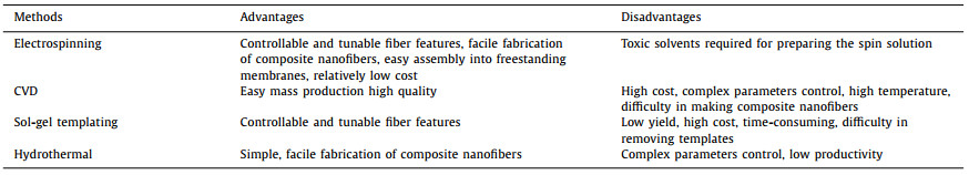
2. ElectrospinningElectrospinning is a versatile approach to fabricate 1D nanofibers with hierarchical structures for energy storage applications. Notably, it can be combined with other synthesis methods such as CVD and hydrothermal to further tailor the structural and compositional features. The main advantages of electrospinning include (ⅰ) the ability to produce large quantities of nanofibers, (ⅱ) facile fabrication of controllable fiber features in terms of morphology, structure, and composition, (ⅲ) easy assembly into 3D freestanding membranes. All these advantages can be transferred to electrospun carbon materials by a simple carbonization process. Table 1 presents the comparison between electrospinning and other synthetic methods (e.g., CVD, hydrothermal and templating) in making CNFs. It can be found that electrospinning is more competitive in fiber preparation in terms of fabrication, processing cost, and controllability.
|
|
Table 1 Comparison of the advantages and disadvantages of four synthesis methods. |
The electrospinning device normally comprises a jet device, a high voltage power supply, and a collector, as illustrated in Fig. 1a [49, 55, 56]. The simplest form of electrospinning utilizes a single nozzle, which can be further developed into a multi-nozzle to make core–shell fibers and others [57]. In general, various nanofibers can be obtained by electrospinning in three steps [58]. To begin with, the droplets at the spinneret are gradually stretched to form a "Taylor cone" after applying a high voltage. Next, the solution will be ejected from the tip of the spinneret when the electrostatic force on the liquid surpasses the surface tension, and high-frequency bending, stretching, and splitting then occur. Finally, the jets solidify into fibers as the solvent volatilizes and deposit on the collector [59].

|
Download:
|
| Fig. 1. (a) Schematic illustration of a typical electrospinning device. (b) Factors influencing the fiber formation by the electrospinning technique. | |
Electrospinning technology is one of the most convenient and effective methods to prepare nanofibers owing to its simple equipment, convenient operation, and product diversification [60]. Many factors affect the preparation of nanofibers, and these factors can be divided into three categories: solution parameters, process parameters, and environmental parameters. How these factors influence the fiber diameter is shown in Fig. 1b.
2.2.1. Solution parametersViscosity and surface tension: A uniform polymer solution is critical to electrospinning. Generally, viscosity is a key factor determining the spinning processes. If the viscosity is too low, discontinuous spinning will occur. On the other hand, with a high viscosity solution, the solution is difficult to jet from the nozzle. Therefore, a suitable solution is required for the fabrication of uniform fibers [41]. In an appropriate viscosity range, the diameter of the nanofibers becomes larger as the viscosity increases. In addition, the surface tension of the electrospinning solution should also be controlled. A high surface tension leads to the formation of unstable fiber with plenty of beads. As the surface tension is affected by both polymers and solvents, the type and molecular weight of the polymers, as well as the solvents, need to be optimized to obtain uniform and continuous electrospun nanofibers [59].
Conductivity: Conductivity is another key factor influencing jet formation because the repulsion of the charges at the surface splits the droplets to form nanofibers. If the conductivity of the solution is low, it is hard to form nanofibers. However, with the increase of conductivity, the diameter of electrospun nanofibers will become smaller. The introduction of surfactants and salt additives are two well-known methods to tune the conductivity of the solution [61].
2.2.2. Process parametersVoltage: The applied voltage determines the density of charge, directly affecting the strength of the electric field. Only when the threshold voltage is reached, the nanofibers will form. When the voltage is low, the electric field is unable to accelerate the jets to form fibers. Previous studies have shown that approaching the minimum critical voltage is beneficial to obtain thinner fibers. In this range, the jet will be accelerated with the increase of voltage, resulting in a higher degree of crack differentiation and smaller diameter nanofibers. However, beyond a critical point, the increase in voltage will incur unstable jets, giving rise to the formation of large beads [58].
Feed rate and receive distance: Feed rate is an important factor that affects the diameter and geometry of the electrospun nanofibers. A high feed rate will result in fibers with a large diameter. In contrast, a low feed rate would enable enough time for solvent evaporation, but the yield is low [62]. Therefore, an appropriate feed rate should be used. The receive distance, that is the gap between the tip and the collector, also affects the fiber diameters and geometry. With the increase of the distance, the diameter of the nanofibers will decrease [63].
2.2.3. Environment parametersEnvironmental factors, such as temperature, humidity, air velocity, also have a certain impact on the preparation of nanofibers [59]. For a given polymer solution, the increase in temperature incurs a decreased viscosity of the solution and an increased evaporation rate of the solvent, and thereby decreases fiber diameter. The solvent on the nozzle tip will evaporate too fast under low humidity, leading to solidification at the nozzle tip, thus interrupting the electrospinning process. By contrast, a higher humidity results in a weaker tensile effect on fibers, generating thicker fibers.
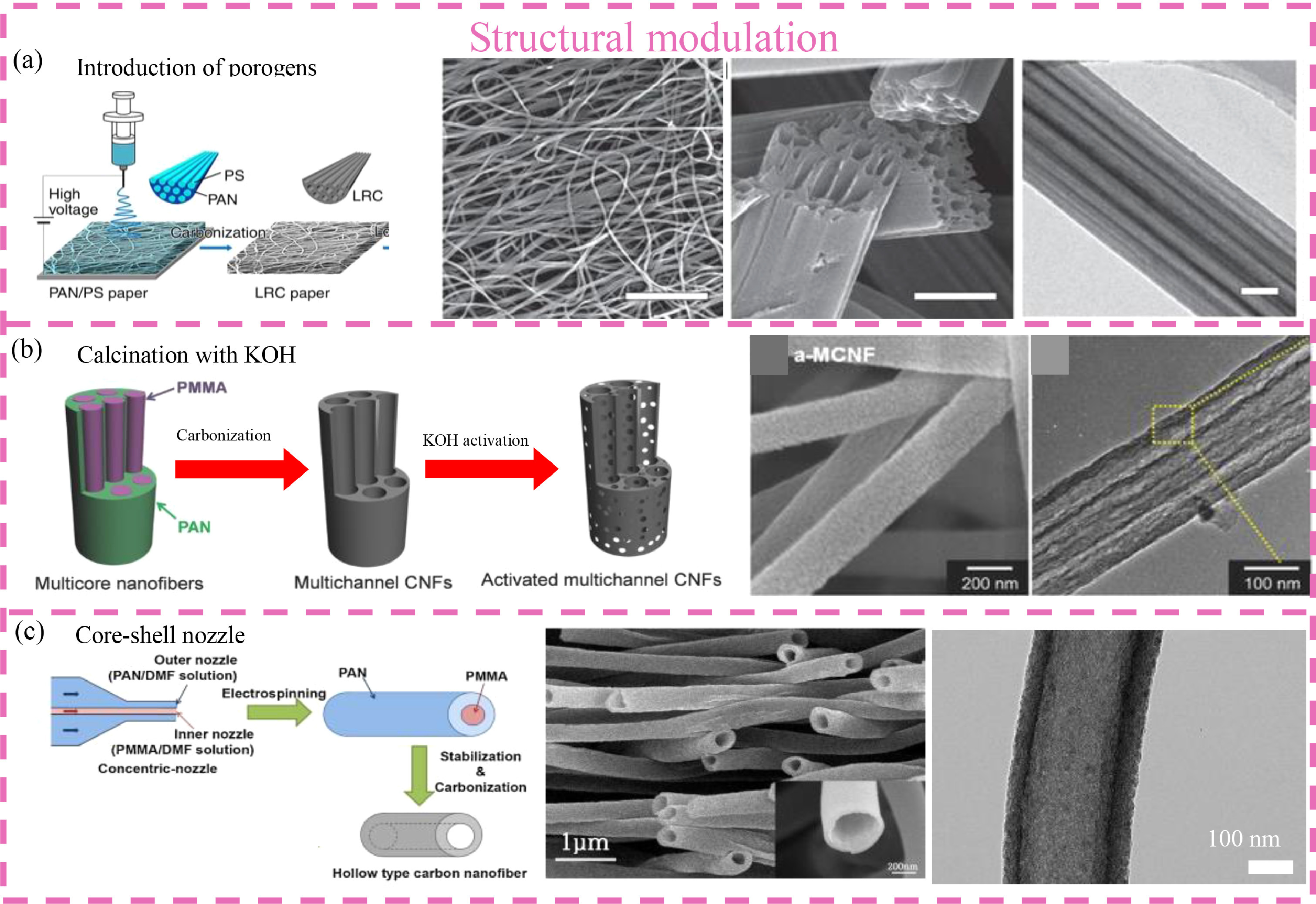
2.3. Electrospun CNFs 2.3.1. Structural modulationPAN is a dominant precursor for making high-performance CNFs. After spinning, the PAN nanofibers can be converted into CNFs through stabilization and carbonization [38, 64]. The structure, morphology, and pore architecture of electrospun CNFs can be tailored by various parameters such as precursor composition, calcination condition, and type of nozzle [46, 58, 65]. For example, the addition of porogens in the precursor solution can be used to produce multi-channel porous CNFs [49]. Lou et al. synthesized multi-channel CNFs by electrospun the PAN/polystyrene (PS) fibers followed by high-temperature annealing (Fig. 2a) [66]. The larger PS droplets in the spinning solution are uniformly stretched by the applied electric field during electrospinning. After calcination, the PS decomposed and generated continuous channels in the PAN-derived CNF matrix. Similarly, poly(methyl methacrylate) (PMMA) and PVP have also been utilized as soft templates to create pores in CNFs [47, 64, 67, 68]. Apart from organic porogens, metal (e.g., Fe, Ni, Co) and inorganic (e.g., SiO2) porogens are also widely employed to fabricate porous CNFs, but the removal of these hard templates is tedious [69, 70]. In addition to tune the composition of the electrospinning solution, porous CNFs can also be prepared by KOH activation. For example, Lee and co-workers synthesized activated multichannel CNFs by KOH activation, as illustrated in Fig. 2b [71]. Both the scanning electron microscopy (SEM) and transmission electron microscopy (TEM) images show a rough surface and a 3D nanoscale porous network of the activated CNFs. The use of different types of nozzles is another promising way to fabricate CNFs with novel architectures [65, 72]. For example, coaxial electrospinning has been adopted to fabricate core–shell and hollow CNFs [73]. Park et al. prepared hollow activated carbon nanofibers (H-ACNFs) using coaxial electrospinning with PMMA and PAN as the core and carbon shell precursor, respectively (Fig. 2c) [74]. After stabilization, carbonization, and activation, H-ACNFs showed a large surface area of 1037.5 m2/g and an average pore diameter of 17.4 nm.

|
Download:
|
| Fig. 2. (a) Electrospinning of precursor nanofibers of PAN/PS, followed by carbonization to form the LRC paper. TEM image of LRC nanofibers: Scale bars, 20 µm and 500 nm; PAN/PS weight ratio = 1:0.2. Reproduced with permission [66]. Copyright 2019, Wiley. (b) Illustration of the sequential fabrication steps for the activated multichannel carbon fibers, FE-SEM and TEM. Reproduced with permission [71]. Copyright 2016, Wiley-VCH. (c) The fabricating process of hollow type activated carbon nanofiber, SEM and TEM images for H-ACNF. Reproduced with permission [74]. Copyright 2013, Elsevier. | |
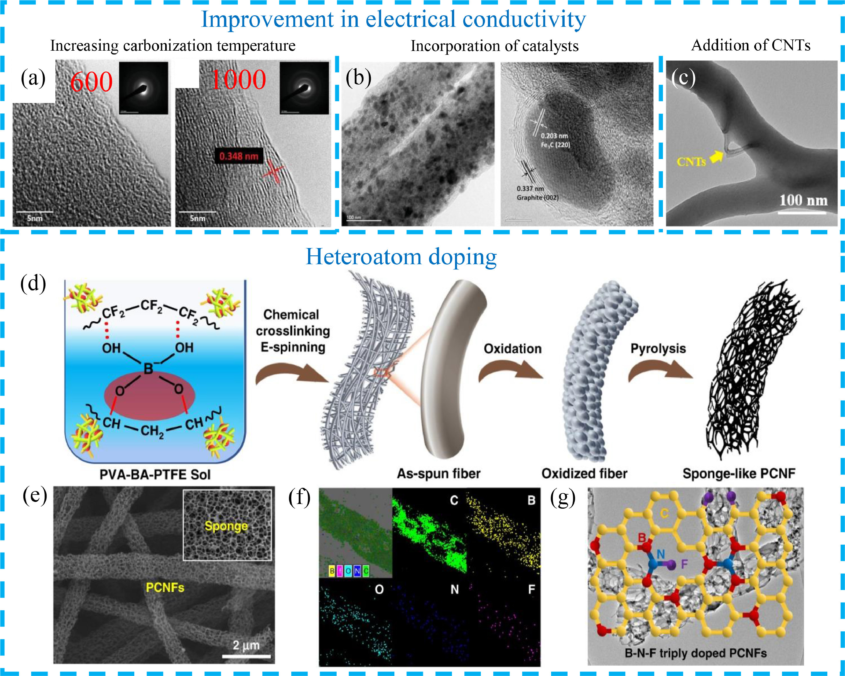
Ideally, CNFs should have sufficiently high conductivity to establish conductive networks for electron transfer in battery applications. There are several ways to improve the conductivity of CNFs, including increasing carbonization temperature, incorporating catalysts, and adding highly conductive materials (e.g., CNTs and graphene). Lee et al. improved the electrical conductivity of CNF films by increasing the carbonization temperature (0.0012 S/m at 600 ℃ and 125.25 S/m at 1000 ℃) [75]. The TEM images in Fig. 3a indicate that the CNFs with a higher graphitization degree can be obtained when the carbonization temperature increases. However, a high calcination temperature will reduce the nitrogen content in CNFs, which may affect their electrochemical performance [76, 77]. As an alternative approach, CNFs with high graphitization can be realized with the assist of catalysts (e.g., Fe and Ni) at a low temperature [78, 79]. As shown in Fig. 3b, the addition of Fe salt in the precursor solution can catalyze the formation of graphitic carbon in the CNFs, thus improving the electrical conductivity [79]. It is worth noting that the containing of these catalysts in CNFs may affect their applications. In addition to the above-mentioned methods, the introduction of CNTs or/and graphene is another intriguing way to increase the electrical conductivity of CNFs [48, 58]. A simple way is to disperse CNTs or graphene into the precursor solution before electrospinning [80]. For example, Song et al. embedded CNTs in CNFs via a facile electrospinning process (Fig. 3c) [81]. The addition of CNTs improves the electrical conductivity of the overall carbon matrix and promotes the uniform deposition of Li metal. In addition, graphene has been incorporated into CNFs to improve their electrical conductivity [82].

|
Download:
|
| Fig. 3. (a) TEM images of ACNFs carbonized at 600 and 1000 ℃, respectively, showing different degrees of graphitization near the surface. The insets are the selected-area electron diffraction (SAED) patterns. Reproduced with permission [75]. Copyright 2019, Wiley-VCH. (b) TEM images of Fe/CNFs with Fe3C particles. Reproduced with permission [79]. Copyright 2014, Elsevier. (c) TEM image of CNTs/CNFs. Reproduced with permission [81]. Copyright 2020, Elsevier. (d) Schematic illustration showing the fabrication process of triply doped porous CNFs. (e) SEM, (f) EDS mapping, and (g) TEM images of triply doped porous CNFs. Reproduced with permission [90]. Copyright 2019, Springer Nature. | |
Chemical doping of CNFs is a well-known approach to improve the electrochemical activity for energy storage and conversion. A variety of heteroatoms such as boron (B), nitrogen (N), phosphorus (P), and sulfur (S) have been explored to manipulate the electronic structure and surface chemistry of carbonaceous materials [83]. Among them, nitrogen doping is commonly adopted to tailor the electrochemical reactivity, electrical conductivity, and wettability of electrospun CNFs [84]. For instance, Chen et al. used urea as an N-doping agent to prepare N-doped CNFs for sodium-ion batteries. The results showed the N-doped CNFs with a high nitrogen content of 19.06 wt% delivered a high capacity of 354 mAh/g at 50 mA/g [85]. In addition to single nitrogen doping, dual-doped CNFs have become popular because of the boosted electrochemical activity originating from the synergistic effect. Kim et al. reported the fabrication of B/N co-doped 3D CNFs as a binder-free electrode [86]. It was found that the B/N co-doped 3D CNFs had an enlarged specific surface area and between wettability in aqueous electrolyte, as compared to N-doped CNFs. Consequently, they delivered a much higher specific capacitance of 295 F/g at 0.5 A/g, while the N-doped CNFs displayed a specific capacitance of only 126 F/g at the same condition. Besides, N/S- and N/P-codoped CNFs have also been explored to improve electrochemical performance [87, 88]. Meanwhile, ternary doping also emerges because of the synergistic effects among the heteroatoms [89]. For example, Ding and coworkers fabricated B/F/N co-doped sponge-like porous CNFs by chemical crosslinking, electrospinning, and pyrolysis (Fig. 3d) [90]. As shown in Figs. 3e–g, B, F and N elements have been homogeneously doped into the porous CNF matrix. In addition, the porous CNFs have a relatively high surface area of 750.6 m2/g and outstanding conductivity of 980 S/cm. It should be noted that the underlying mechanisms of co-doping remain elusive. The combination of theoretical calculations and experimental methods could help understand the mechanistic insights of the doping effect, which deserves more effort.
In this section, we give a brief introduction to the modification of electrospun CNFs in terms of structural modulation, electrical conductivity, and heteroatom doping. In fact, the traditional electrospun CNFs normally exhibit a lower electrical conductivity than that of graphene and CNTs, owing to the low carbonization temperature. Additionally, electrospun CNFs with a solid interior also exhibit a much lower specific surface area compared to that of CNTs and graphene. Therefore, various strategies have been reported to improve the properties of electrospun CNFs. For example, structural engineering is an effective strategy to enlarge the specific surface area of CNF via the introduction of porogen, KOH activation, and the utilization of novel nozzles. However, the creation of a great many pores will result in a trade-off in mechanical robustness and electrical conductivity. Increasing carbonization temperature, incorporating catalysts, and adding highly conductive materials have been established to improve the electrical conductivity of CNFs. Heteroatom doping of electrospun CNFs can substantially affect their electrochemical performance by manipulating the electronic conductivity, surface area, and graphitization degree. The doping configuration and concentration in the carbon lattice have a notable impact on electrochemical behaviors. N-doped carbon-based materials have been extensively studied, but the doping impacts of other heteroatoms on CNFs, such as F, P and S, remain ambiguous. Although substantial progress has been achieved in rationally designed electrospun CNFs, it remains a significant challenge to integrate all the attributes in the same CNFs without compromising the individual properties.
3. Electrospun CNF hosts for LMAs 3.1. CNF hostsThanks to their unique features such as high aspect ratio with large active sites, well-developed electron/ion pathways, and fast strain relaxation during electrochemical reactions, CNFs have been recognized as promising hosts for LMAs. In addition, CNFs are long, mechanically strong, and flexible, and thereby they can serve as the building block to construct various sophisticated 3D structures. In this section, we will introduce the impact of the conductivity, surface property, and defect of pure CNF on Li plating/stripping performance.
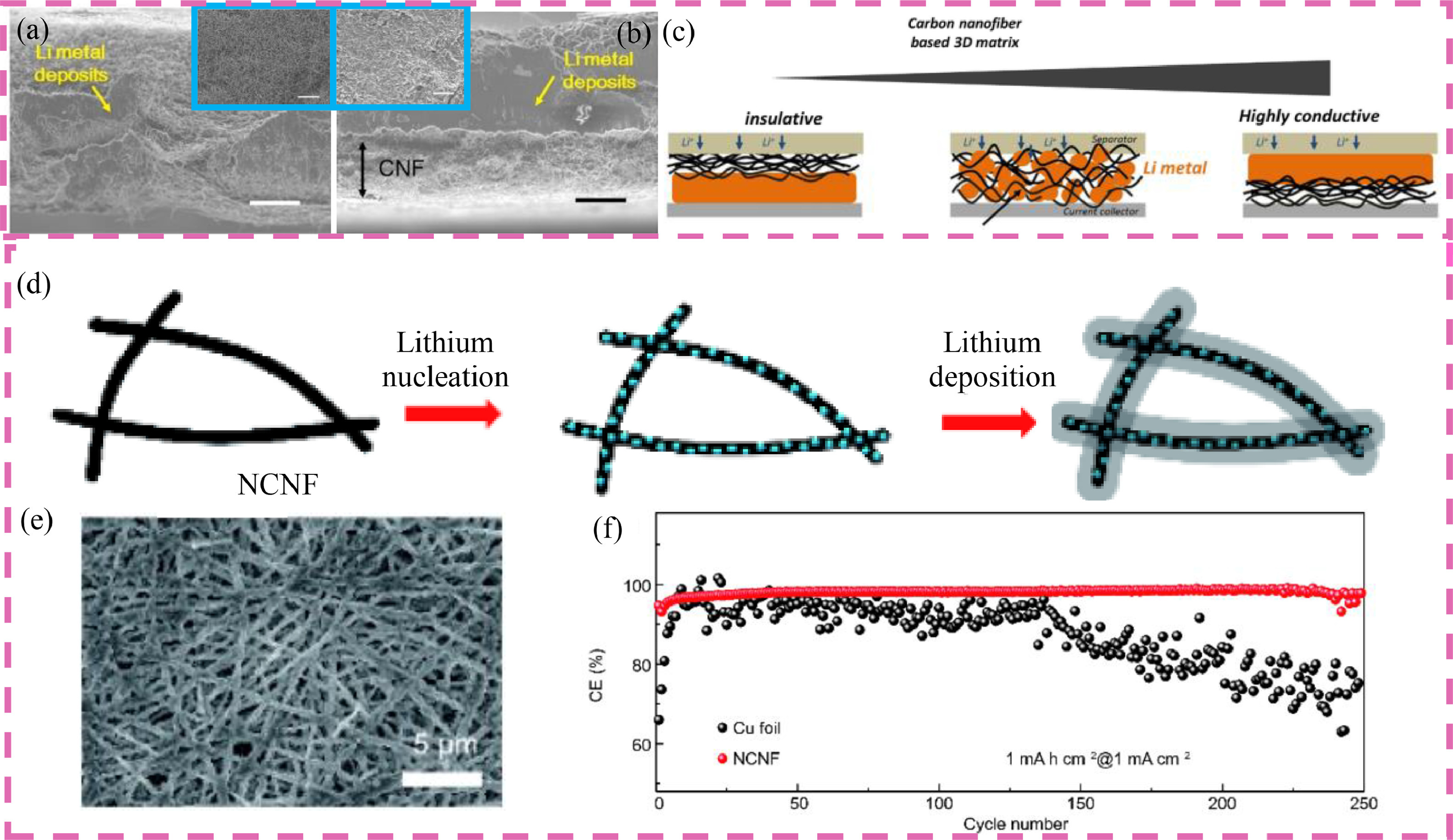
Since the deposition of Li has a strong correlation with the conductivity of the host, Matsuda presented a detailed study on Li deposition behavior on CNFs with different conductivities [91]. The PAN nanofibers were first prepared followed by calcination at 500 and 900 ℃, which is referred to as CNF-500 and CNF-900, respectively. It was found that Li metal is more inclined to deposit on the surface of CNF-900, whereas most Li is stored inside the skeleton for CNF-500, as shown in Figs. 4a and b. In addition, they also observed that Li metal would deposit at the interface between the insulative fiber matrix and the Ni foil, corroborating the significant importance of electrical conductivity for Li deposition (Fig. 4c).

|
Download:
|
| Fig. 4. Side-view SEM image of (a) CNF-500 and (b) CNF-900 removed from electrochemical cells after Li metal deposition at a capacity of 5.0 mAh/cm2. (c) Schematic illustration of the accumulation of Li metal deposits in the CNF matrix. Reproduced with permission [91]. Copyright 2019, Elsevier. (d) Schematic illustration of the Li nucleation and plating on NCNF. (e) SEM image of the NCNF with 0.5 mAh/cm2 deposited Li. (f) Coulombic efficiency of Li plating/stripping on/from the Cu and the NCNF current collector for 1 mAh/cm2 Li at a current density of 1 mA/cm2. Reproduced with permission [93]. Copyright 2018, Springer. | |
Although the conductivity of CNFs has a great impact on the deposition behavior of Li metal, the poor affinity of CNFs to Li would result in inhomogeneous Li deposition associated with high overpotential, especially at high area currents. Heteroatom doping and surface functionalization are two main approaches to improve the intrinsic Li wettability of carbon materials. It has been reported that nitrogen doping, such as pyridinic, pyrrolic, and quaternary nitrogen atoms, can enhance the Li wettability of carbon-based hosts and direct Li deposition [92]. In this regard, Wu et al. prepared a 3D N-doped CNF matrix (NCNF) with a high N doping of 9.5 at% (Fig. 4d) [93]. The high N doping and good electrical conductivity of the 3D skeletons offer abundant nucleation sites for Li, resulting in small polarization and dendrite-free Li deposition (Fig. 4e). As displayed in Fig. 4f, the NCNF exhibits much more stable CEs than the Cu counterpart, indicating the great potential of using N-doped carbon matrices for LMAs.
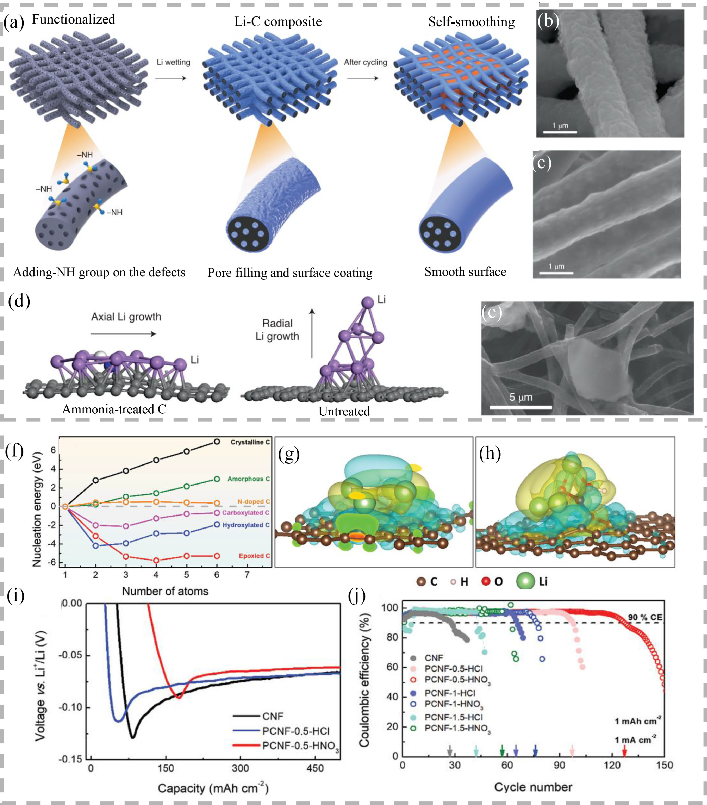
The functionalization of CNF surface is another important way to alleviate the poor wettability of carbon to Li. To this end, Niu et al. fabricated amine-functionalized 3D mesoporous CNFs to serve as a 3D Li host by taking advantage of the strong interaction between ‒NH and Li [94]. The composite Li–C electrode was further prepared by a smooth infusion of molten Li into the functionalized CNFs, as illustrated in Fig. 5a. The SEM image in Fig. 5b shows that the pristine Li–C fibers have a rough surface. After 10 cycles of deposition and stripping, the surface of pristine Li–C fibers becomes smoother, indicating a "self-smoothing" phenomenon (Fig. 5c). According to the density functional theory (DFT) calculations, the binding between Li and the –NH group is thermodynamically favorable, which would promote the nucleation of Li occurring on the –NH groups and mediate further growth of Li metal on the carbon surface, realizing self-smoothing Li deposition (Fig. 5d). For comparison, on the untreated carbon surface, Li tends to grow vertically along the fiber direction, giving rise to heterogeneous large Li agglomerates, which is confirmed by the SEM (Fig. 5e). Thanks to the self-smoothing deposition of Li on amine-functionalized CNFs, the as-prepared Li–C anode paired with a lithium nickel–manganese–cobalt oxide cathode delivered an energy density of 350–380 Wh/kg at a cell level and exhibited a long lifespan of 200 cycles.

|
Download:
|
| Fig. 5. (a) Schematic illustration of self-smoothing behavior in the Li–C anode. SEM image of (b) a pristine rough Li–C film before cycling and (c) Li–C film after 10 plating/stripping cycles. (d) DFT calculation of Li growth on treated and untreated carbon surfaces. (e) SEM image of Li plating on the untreated carbon film. Reproduced with permission [94]. Copyright 2019, Springer Nature. (f) Nucleation energies of Li plating on carbon of different crystallinities and with different functional groups. Electron density differences of Li nucleus comprising four Li atoms formed on the surface of (g) crystalline carbon and (h) carboxylated carbon. (i) Initial nucleation overpotentials of neat CNF and PCNF electrodes. (j) CEs of PCNF electrodes upon repeated Li plating/stripping cycles. Reproduced with permission [30]. Copyright 2018, Wiley-VCH. | |
Similarly, Cui et al. revealed the relationship between Li deposition and the surface characteristics of CNFs [30]. Fig. 5f shows the nucleation energy of Li plating on CNFs with different crystallinities and various functional groups. A more negative value indicates a higher Li affinity. It was found that the nucleation energy of Li on the crystalline carbon rose rapidly with the increasing number of Li atoms, probably stemming from the mismatch between bcc-structured Li and the hexagonal carbon. Although the amorphous carbon and N-doped carbon show smaller nucleation barriers, the values are still positive. Intriguingly, the oxygen-containing functional groups such as hydroxyl, epoxy and carboxyl, can significantly reduce the nucleation energy to negative values after reacting with the carbon surface. The above results manifest the strong interaction between Li and oxygenated groups, which redistributes the electron density and in turn weakens the interaction between the Li and carbon, as reflected by the electron density differences in Figs. 5g and h. As a proof of concept, oxygen-containing functional groups were created on electrospun CNFs by HNO3 or HCl treatment. The comparative overpotential measurements of CNF and PCNF containing functional groups show that the pristine CNF electrode has the largest overpotential, whereas porous CNF electrode treated by HNO3 exhibits an overpotential of only ~32 mV (Fig. 5i). The small overpotential in PCNF-0.5-HNO3 is beneficial to homogeneous Li deposition, thus avoiding the formation of Li dendrites. The PCNF-0.5-HNO3 electrode demonstrated stable CEs for more than 120 cycles at a constant current of 1 mA/cm2 with a plating/stripping time of 1 h (Fig. 5j).
3.2. CNF-based composite hostsAs discussed above, the surface functionalization and defects can increase the affinity of CNFs to Li, thus contributing to dendrite-free Li plating. However, it should be noted that these strategies would potentially affect the electrical conductivity, resulting in high interfacial resistance and large polarization. Anchoring nucleation seeds that can react with Li is an attractive approach to direct Li nucleation at specific sites with smooth deposition. Based on this rationale, many types of nucleation seeds have been explored, including metals (e.g., Zn, Ag, Au) [95-97] and non-metals (e.g., Si, ZnO) [98, 99]. In this section, we will give a systematic discussion on the fabrication of CNF-based composite hosts for LMAs and the underlying mechanisms in regulating Li deposition.
3.2.1. Metal/CNF compositesIt has been reported that metal nanoparticles such as Zn, Ag, and Au can form alloys with Li owing to their high solubility in Li. Additionally, the formed alloys have a similar crystalline structure as Li and good wettability to Li, which is beneficial to Li deposition [95]. As such, rational implantation of these nucleation seeds on CNF skeletons would increase the lithiophilicity of the substrate, promoting a large critical nuclei size and a smaller nucleation overpotential. Hu et al. applied a novel Joule heating method to synthesize CNFs with ultrafine Ag nanoparticles on their surface (Fig. 6a) [100]. Governed by the uniform Ag nanoseeds, Li tends to nucleate at the Ag seeds on the surface of CNFs and is further accommodated in the 3D substrate without dendrites (Fig. 6b). For comparison, Li deposition on the pure CNF substrate is unregulated. The Ag-modified 3D CNF composite substrate exhibited a low nucleation overpotential of ~25 mV, and excellent plating/stripping stability at 0.5 mA/cm2 with a deposition capacity of 1 mAh/cm2 for more than 500 h.

|
Download:
|
| Fig. 6. (a) Schematic illustration of Li nucleation and growth seeded by Ag nanoparticles on CNFs. (b) SEM images of pristine AgNP/CNFs without Li deposition, initial Li nucleation on AgNP/CNFs, 1 mAh/cm2 of Li deposited on CNFs guided by AgNPs, and AgNP/CNFs after the first plating/stripping cycle. Reproduced with permission [100]. Copyright 2017, Wiley-VCH. (c) Schematic illustration of the synthesis of Ag@CMFs. (d) Characterization of the Ag@CMF and CMF materials. (e) CE of Li deposited on b-Cu, CMFs and Ag@CMFs at different current densities for the same capacity of 1 mAh/cm2. Reproduced with permission [96]. Copyright 2021, American Association for the Advancement of Science. (f) Schematic illustration of the synthesis of NCH@CFs. (g) Initial nucleation overpotentials of Cu, NC@CF, NCH@CF and CF anode. (h) SEM images of NCH@CFs after depositing 6 mAh/cm2 Li at a current of 1 mA/cm2. Reproduced with permission [101]. Copyright 2021, Wiley-VCH. | |
In addition, Zhang et al. incorporated Ag nanoparticles into N-doped carbon macroporous fibers (Ag@CMFs) and successfully prepared a composite CMF skeleton [96]. The Ag@CMFs were prepared by electrospun a mixed solution containing Ag-deposited SiO2 nanospheres and PAN. Afterward, the electrospun fibers were carbonized at 700 ℃ for 3 h followed by an etching process (Fig. 6c). As shown in Fig. 6d, the nanofibrous structures are well preserved after KOH etching and the Ag nanoparticles are uniformly decorated on the wall of the hollow carbon sheath. The galvanostatic plating/stripping efficiencies were evaluated and the results showed that Ag@CMF electrode manifested high CEs at current densities ranging from 1 mA/cm2 to 5 mA/cm2, indicating the excellent regulative effect of the 3D Ag@CMFs (Fig. 6e). The excellent Li plating/stripping performance can be attributed to the unique microporous nanostructures and the synergistic effect between the lithiophilic N-doped carbon and Ag nanoparticles, thus guiding uniform nucleation and growth of Li and accommodating the huge volume change. Apart from Ag, Au has also been embedded in the hollow CNFs for mediating Li deposition. Kim et al. employed a co-axial electrospinning technique to fabricate lithiophilic Au nanoparticles-modified hollow carbon fibers (Au@HCFs) for LMAs [51]. The ex-situ TEM revealed that the Au nanoparticles would react with Li to form AuxLi at the beginning of the lithiation process, and the formed AuxLi alloys further promote the preferential deposition of Li inside the HCFs. After fully stripping, the Au nanoparticles recovered and the overall morphology of the Au@HCFs remained unchanged.
Considering the high cost of Ag and Au, other cheap metals have been implanted in CNFs to direct Li nucleation and growth. For example, Chen used Ni–Co bimetallic particles as nucleation sites and uniformly embedded these particles into nitrogen-doped carbon fibers (NCH@CFs) by electrospinning and carbonization process (Fig. 6f) [101]. As shown in Fig. 6g, the NCH@CF host displays the smallest nucleation overpotential during initial Li plating. After the deposition of 6 mAh/cm2, Li at 1 mA/cm2, no visible Li dendrites were observed and the NCH@CF host retained porous ends (Fig. 6h). In addition, the as-prepared Li-NCH@CF electrode displayed stable plating/stripping at 1 mA/cm2 for 1200 h. The highly dispersed Ni–Co particles and the lotus-root-like hollow structures could reduce low current density, guide uniform Li deposition, and accommodate the volume change to enhance the structural stability, thus contributing to excellent electrochemical performance. As another example, Fang et al. synthesized N-doped amorphous zinc-carbon multichannel fibers (CC-Zn-CMFs) for LMAs [102]. The 3D microporous structures can effectively reduce local current density, while the zinc nanoparticles and the N-doped carbon matrix lead to small nucleation barriers for smooth Li growth. Consequently, the CC-Zn-CMFs presented high CEs at various current densities and the symmetric CC-Zn-CMFs-Li|CC-Zn-CMFs-Li cells showed ultralong cyclic stability for more than 2000 h. The full cell equipped with the as-developed anode and a LiFePO4 cathode demonstrated remarkable cyclic performance and rate performance (104 mAh/g at 5 C).
3.2.2. Non-metallic inorganic compounds/CNF compositesApart from metal seeds, non-metallic inorganic compounds such as Si and ZnO, also exhibit good affinity to Li, which can be used to improve the lithiophilicity of CNF hosts. For example, Cui et al. designed an electrospun CNF network modified with lithiophilic Si coating, which was then used as the scaffold for Li encapsulation [99]. The CNF skeletons were obtained by carbonization of electrospun PAN nanofibers, and a thin Si was then coated on the CNF skeletons by CVD. As shown in Fig. 7a, the pristine CNFs have a smooth surface with a diameter of 200 nm, while Si-coated CNFs exhibit a rough surface. The wettability test shown in Fig. 7b confirms that the unmodified CNFs could not be wet by the molten Li, while Si-coated CNFs show good wettability to molten Li. The SEM images further confirm that Li is confined inside the Si-coated CNF matrix (Figs. 7c and d). Moreover, the XRD patterns revealed the existence of both Li21Si5 and Li inside the scaffold, and the formation of Li21Si5 is responsible for the good wettability of Si-coated CNF to Li (Fig. 7e).

|
Download:
|
| Fig. 7. (a) TEM images of the uncoated carbon fiber and the Si-coated carbon fiber. (b) Time-lapse images of Li melt-infusion process for lithiophilic and lithiophobic materials. SEM images of the modified carbon fiber network (c) before and (d) after Li infusion. (e) XRD pattern collected from the modified carbon fiber before and after Li infiltration. Reproduced with permission [99]. Copyright 2016, National Academy of Sciences. (f) Optimized geometrical structures and corresponding binding energies of a Li atom adsorbed on carbon, SiO2 (101) surface, TiO2 (101) surface, amorphous SiO2 and amorphous TiO2. (g) Cycling performance comparisons of symmetrical cells using a Li@Cu, Li@CF, and Li@PCSF composite anode. Reproduced with permission [103]. Copyright 2019, Wiley-VCH. (h) Schematic illustration of the working principle of G-CNF in regulating lithium deposition. Reproduced with permission [104]. Copyright 2019, Wiley-VCH. (i) Schematic illustration of Li plating/stripping behaviors on Cu foil, 3D EC and 3D MIEC electrodes. Reproduced with permission [107]. Copyright 2019, Wiley-VCH. | |
In addition to Si, Xue et al. reported that SiO2 and TiO2 exhibit good lithiophilicity, which can be used to guide homogeneous Li deposition [103]. A 3D porous core–shell carbon fiber (PCSF) with uniformly distributed amorphous SiO2 and TiO2 nanoparticles was prepared. According to the DFT calculations, the binding energy of Li and amorphous SiO2 was −6.73 eV, while that for amorphous TiO2 was −2.20 eV. These values are much higher than −1.21, −3.66 and −1.97 eV for pure carbon, crystallized TiO2, and crystallized SiO2, respectively (Fig. 7f). The higher the binding energy, the stronger the anchoring effect for the adsorption, nucleation, and growth of Li. Compared with the Li@CF, and Li@Cu counterparts, the Li@PCSF electrodes exhibited excellent cycle stability with ultralow overpotentials at 2 and 4 mA/cm2 (Fig. 7g). Therefore, the assembled full cell equipped with the Li@PCSF anode and the LiNi0.5Co0.2Mn0.3O2 cathode delivered excellent rate performance of ~80 mAh/g at 20 C and remarkable cycle performance with a capacity decay of 0.077% per cycle for 200 cycles at 10 C.
It has been reported that Li plating initiates on the top region of a 3D conductive scaffold, because of the higher Li-ion concentration and lower transport resistances, which would trigger problematic Li dendrite growth. To resolve this problem, Nan et al. designed gradient-distributed ZnO particles on a 3D conductive CNF scaffold (G-CNF) to regulate Li deposition [104]. As illustrated in Fig. 7h, the introduction of gradient-distributed, lithiophilic ZnO nanoseeds in 3D CNF scaffolds facilitates Li growth at the bottom of the 3D host, reducing potential Li dendrites formed on the top surface and accommodating the Li metal in the skeleton. Thanks to the above advantages, the G-CNF electrode had an average CE of 98.1% at 0.5 mA/cm2 for 700 cycles. Even at a high areal current of 5 mA/cm2, the G-CNF electrode still displayed stable cyclic performance for more than 200 cycles with a CE of 96.0%.
As an electron conductive matrice, CNFs allow Li to be plated inside the skeleton. However, the limited Li-ion conductivity of CNF would restrain the mass transport of Li, thus resulting in poor rate performance [105]. In this regard, both the ion and electron transport in CNF scaffolds has to be accelerated for high-capacity and high-rate LMBs [5, 106]. Recently, Zhang et al. proposed a mixed ion- and electron-conducting (MIEC) substrate by introducing Li6.4La3Zr2Al0.2O12 (LLZO) nanoparticles into 3D CNFs [107]. The incorporation of LLZO nanoparticles is beneficial to homogeneous Li-ion flux and alleviative Li+ depletion near the electrode surface during Li plating/stripping processes, rendering uniform Li deposition and dissolution (Fig. 7i). As a result, the plated Li was uniformly deposited on the surface of the MIEC nanofibers without dendritic Li. For comparison, sporadic Li microparticles were found on the pure CNF substrate. Therefore, both the electronic and ionic conductivity of the hosts should be optimized to achieve high-capacity and high-rate Li composite anodes.
3.3. SummaryIn this section, we discuss the recent progress of CNF-based skeletons for LMAs. Benefiting from their large specific surface areas, good electronic conductivity, high mechanical strength, and easy functionality, CNF-based scaffolds have been widely employed as Li metal hosts. For pure CNFs, the poor affinity of CNFs to Li leads to a large nucleation barrier, which triggers the growth of dendrite and/or mossy Li, especially at high current densities. Heteroatom doping and surface functionalization offer a higher lithiophilicity, leading to a much more uniform Li deposition and higher plating/stripping stability. In addition, the implantation of nucleation seeds that are soluble with Li to form alloys can substantially improve the wettability with Li, thus directing Li nucleation with controllable morphology. This is because the implanted seeds can increase the critical nuclei size and lower the nucleation overpotential. Table 2 summarizes the fabrication methods and electrochemical performance of the representative electrospun CNF-based skeletons for LMAs. One can find that heteroatom doping, surface modification, and lithiophilic treatment of CNFs can lower the overpotential and improve Li plating/stripping CEs, as compared to pure CNFs. However, it should be noted that the construction of these sophisticated structures would inevitably increase the fabrication cost. In addition, other strategies, including the optimization of electrolyte formula and construction of artificial SEI layers, should be combined to build safer and longer life LMAs.
|
|
Table 2 Comparison of the advantages and disadvantages of four synthesis methods. |

Li metal is recognized as an ultimate anode material for high-energy-density Li batteries. However, LMAs suffer from low CEs and safety hazards originating from the uneven Li deposition and further the Li dendrites, preventing their commercial applications. The utilization of CNF-based skeletons for LMAs is a promising strategy owing to their multiple benefits, which can address several main issues faced by LMAs, as shown in Fig. 8. In this review, we have systematically reviewed the principles of electrospinning and discussed the influence of processing, solution, and environmental parameters on electrospun nanofibers. In addition, various modification methods are introduced to tune the pore structures, electrical conductivity, and electrochemical activity of CNFs. Finally, we summarize the recent progress of using CNFs hosts (pure CNF and CNF-based composites) to improve the electrochemical performance of LMAs.

|
Download:
|
| Fig. 8. Schematic illustration showing the benefits of CNF-based hosts for Li metal anodes. | |
Although significant progress has been achieved, issues and challenges remain to be resolved. The following are some of the main challenges in the development of CNF-based architectures for LMAs.
(1) Scalable and continuous manufacturing of electrospun CNF-based architectures for LMAs applications is still insufficient. In addition, the production of CNFs with various structures such as hierarchical, branched, core–shell, is still costly. Therefore, large-scale fabrication of CNFs with low cost, desirable performance, and controllable structures is necessary.
(2) Design and rational assembly of CNF-based skeletons is another intriguing direction worth exploration because the structure and morphology of CNFs have a significant impact on electrochemical performance. For example, CNF-based structures normally contain many gaps/pores among/inside the skeletons, resulting in limited volumetric energy. Regarding the random distribution of individual filament in most electrospun CNFs, highly aligned CNF-based scaffolds are encouraged to develop for a higher packing density and faster ion transport channels. Additionally, the interaction and contact between nanofibers should be strengthened to enhance structural integrity. This could be achieved by adding polymers (e.g., PVP) that can partially melt at the early pyrolysis stage or coating with flexible and mechanically strong materials such as graphene, CNTs, and MXenes.
(3) The precise control in the functionalization of CNFs is crucial to LMAs and needs systematic study. Although CNF-based skeletons have good electrical conductivities and large surface areas, the poor lithiophilicity of pure CNFs inevitability induces a large nucleation barrier. Surface modifications by heteroatoms, functional groups, and polar inorganic species offer strong interactions with Li metal and promote homogeneous Li growth. However, these treatments induce defects in CNFs, thus giving rise to lower electrical conductivity, degraded mechanical stability, and inferior chemical stability. Therefore, the complicated interplay and/or trade-off among the different key performance parameters of CNFs should be systematically investigated and optimized. Apart from the homogeneously modified CNFs, the precise modification of CNFs with different properties at different locations (i.e., graded structure) are desirable for governing the deposition of Li.
The cell parameters and criteria for LMAs must be established. For example, the overuse of the electrolyte and the incorporation of CNF-based hosts will compromise the theoretical energy density of Li metal batteries. Meanwhile, very few studies have demonstrated impressive Li plating/stripping performance at high current densities and areal capacities. Therefore, we suggest that the electrochemical performance of LMAs should be evaluated in practical scenarios with details of testing parameters. Beyond that, the electrochemical performance over a wide temperature range should also be studied to extend the utilization of LMBs.
(5) Advanced characterization techniques, especially in-situ and in-operando characterizations, as well as theoretical simulations, are required for a deeper understanding of the structural evolution and fundamental insights during Li plating/stripping. Electrospun CNFs can offer an ideal platform for studying basic scientific questions due to their uniform sizes and morphologies. The fundamentals of reaction mechanisms based on the developed real-time characterization techniques further guide the better design for LMAs."
In conclusion, electrospun CNF-based skeletons are promising for LMAs thanks to their flexibility, porosity, and tunable properties. Substantial efforts have been made on the modification of CNF frameworks to promote uniform and reversible Li plating/stripping, which has significantly improved the electrochemical performance of LMBs. It is envisioned that with the rapid development of new technologies, LMBs will be commercialized in the future.
Declaration of competing interestThe authors declare no conflict of interest.
AcknowledgmentsWe are grateful for support from the National Natural Science Foundation of China (Nos. 22179022 and 22109023), the Industry-University-Research Joint Innovation Project of Fujian Province (No. 2021H6006), the Award Program for Fujian Minjiang Scholar Professorship, and the Talent Fund Program of Fujian Normal University.
| [1] |
X.R. Chen, Y.X. Yao, C. Yan, et al., Angew. Chem. Int. Ed. 59 (2020) 7743-7747. DOI:10.1002/anie.202000375 |
| [2] |
A. Manthiram, Nat. Commun. 11 (2020) 1550. DOI:10.1038/s41467-020-15355-0 |
| [3] |
K.N. Wood, M. Noked, N.P. Dasgupta, ACS Energy Lett. 2 (2017) 664-672. DOI:10.1021/acsenergylett.6b00650 |
| [4] |
L. Ma, Y. Lv, J. Wu, Y. Chen, Z. Jin, Adv. Energy Mater. 11 (2021) 2100770. DOI:10.1002/aenm.202100770 |
| [5] |
Y. Chen, Z. Wang, X. Li, et al., Nature 578 (2020) 251-255. DOI:10.1038/s41586-020-1972-y |
| [6] |
J. Wu, Q. Liang, X. Yu, et al., Adv. Funct. Mater. 31 (2021) 2011102. DOI:10.1002/adfm.202011102 |
| [7] |
L. Ma, J. Wu, G. Zhu, et al., J. Mater. Chem. A 9 (2021) 5232-5257. DOI:10.1039/d0ta10537f |
| [8] |
C. Zhao, X. Yin, Z. Guo, et al., Chin. Chem. Lett. 32 (2021) 2254-2258. DOI:10.1016/j.cclet.2020.12.056 |
| [9] |
J. Cui, T.G. Zhan, K.D. Zhang, D. Chen, Chin. Chem. Lett. 28 (2017) 2171-2179. DOI:10.1016/j.cclet.2017.11.039 |
| [10] |
X. Xu, S. Wang, H. Wang, et al., J. Energy Chem. 27 (2018) 513-527. DOI:10.1016/j.jechem.2017.11.010 |
| [11] |
A. Jana, S.I. Woo, K.S.N. Vikrant, R.E. García, Energy Environ. Sci. 12 (2019) 3595-3607. DOI:10.1039/c9ee01864f |
| [12] |
C. Wei, L. Tan, Y. Tao, et al., Energy Storage Mater. 34 (2021) 12-21. DOI:10.1016/j.ensm.2020.09.006 |
| [13] |
L. Fan, Z. Guo, Y. Zhang, et al., J. Mater. Chem. A 8 (2020) 251-258. DOI:10.1039/c9ta10405d |
| [14] |
C. Jin, T. Liu, O. Sheng, et al., Nat. Energy 6 (2021) 378-387. DOI:10.1038/s41560-021-00789-7 |
| [15] |
L.P. Hou, X.Q. Zhang, B.Q. Li, Q. Zhang, Mater. Today 45 (2021) 62-76. DOI:10.1016/j.mattod.2020.10.021 |
| [16] |
S. Chen, J. Zhang, L. Nie, et al., Adv. Mater. 33 (2021) 2002325. DOI:10.1002/adma.202002325 |
| [17] |
M. Balaish, J.C. Gonzalez-Rosillo, K.J. Kim, et al., Nat. Energy 6 (2021) 227-239. DOI:10.1038/s41560-020-00759-5 |
| [18] |
Q. Yu, K. Jiang, C. Yu, et al., Chin. Chem. Lett. 32 (2021) 2659-2678. DOI:10.1016/j.cclet.2021.03.032 |
| [19] |
W.J. Chen, C.X. Zhao, B.Q. Li, et al., Energy Environ. Mater. 3 (2020) 160-165. DOI:10.1002/eem2.12073 |
| [20] |
Y. Liu, D. Lin, P.Y. Yuen, et al., Adv. Mater. 29 (2017) 1605531. DOI:10.1002/adma.201605531 |
| [21] |
F. Liu, L. Wang, Z. Zhang, et al., Adv. Funct. Mater. 30 (2020) 2001607. DOI:10.1002/adfm.202001607 |
| [22] |
A. Hu, W. Chen, X. Du, et al., Energy Environ. Sci. 14 (2021) 4115-4124. DOI:10.1039/d1ee00508a |
| [23] |
Q. Yun, Y.B. He, W. Lv, et al., Adv. Mater. 28 (2016) 6932-6939. DOI:10.1002/adma.201601409 |
| [24] |
D. Lin, Y. Liu, Z. Liang, et al., Nat. Nanotechnol. 11 (2016) 626-632. DOI:10.1038/nnano.2016.32 |
| [25] |
P. Shi, X.Q. Zhang, X. Shen, et al., Adv. Mater. Technol. 5 (2020) 1900806. DOI:10.1002/admt.201900806 |
| [26] |
L. Ma, J. Cui, S. Yao, et al., Energy Storage Mater. 27 (2020) 522-554. DOI:10.1016/j.ensm.2019.12.014 |
| [27] |
J. Wu, P. Zou, M. Ihsan-Ul-Haq, et al., Small 16 (2020) 2003815. DOI:10.1002/smll.202003815 |
| [28] |
K. Lin, X. Qin, M. Liu, et al., Adv. Funct. Mater. 29 (2019) 1903229. DOI:10.1002/adfm.201903229 |
| [29] |
H. Wang, Y. Liu, Y. Li, Y. Cui, Electrochem. Energy Rev. 2 (2019) 509-517. DOI:10.1007/s41918-019-00054-2 |
| [30] |
J. Cui, S. Yao, M. Ihsan-Ul-Haq, J. Wu, J.K. Kim, Adv. Energy Mater. 9 (2019) 1802777. DOI:10.1002/aenm.201802777 |
| [31] |
J. Zhao, G. Zhou, K. Yan, et al., Nat. Nanotechnol. 12 (2017) 993-999. DOI:10.1038/nnano.2017.129 |
| [32] |
T. Yang, L. Li, F. Wu, R. Chen, Adv. Funct. Mater. 30 (2020) 2002013. DOI:10.1002/adfm.202002013 |
| [33] |
H. Zhang, X. Liao, Y. Guan, et al., Nat. Commun. 9 (2018) 3729. DOI:10.1038/s41467-018-06126-z |
| [34] |
J. Wu, M. Ihsan-Ul-Haq, F. Ciucci, B. Huang, J.K. Kim, Energy Storage Mater. 34 (2021) 582-628. DOI:10.1016/j.ensm.2020.10.007 |
| [35] |
Y. Ma, C. Weimer, N. Yang, et al., Mater. Today Commun. 2 (2015) e55-e61. DOI:10.1016/j.mtcomm.2014.12.003 |
| [36] |
X. Li, Y. Chen, H. Huang, Y.W. Mai, L. Zhou, Energy Storage Mater. 5 (2016) 58-92. DOI:10.14355/ijmme.2016.05.009 |
| [37] |
Kenry, C.T. Lim, Prog. Polym. Sci. 70 (2017) 1-17. DOI:10.1016/j.progpolymsci.2017.03.002 |
| [38] |
G. Liang, J. Wu, X. Qin, et al., ACS Appl. Mater. Interfaces 8 (2016) 23105-23113. DOI:10.1021/acsami.6b07487 |
| [39] |
X. Qin, H. Zhang, J. Wu, et al., Carbon 87 (2015) 347-356. DOI:10.1016/j.carbon.2015.02.044 |
| [40] |
X. Li, M. Wang, R. Li, et al., Comp. Commun. 23 (2021) 100578. DOI:10.1016/j.coco.2020.100578 |
| [41] |
A. Koski, K. Yim, S. Shivkumar, Mater. Lett. 58 (2004) 493-497. DOI:10.1016/S0167-577X(03)00532-9 |
| [42] |
S. Zeng, R. Zhao, A. Li, et al., Appl. Surf. Sci. 463 (2019) 211-216. DOI:10.1016/j.apsusc.2018.08.233 |
| [43] |
Z.L. Xu, B. Zhang, J.K. Kim, Nano Energy 6 (2014) 27-35. DOI:10.1016/j.nanoen.2014.03.003 |
| [44] |
M.V. Qanati, A. Rasooli, M. Rezvani, Polym. Bull. (2021). DOI:10.1007/s00289-020-03520-w |
| [45] |
L. Li, S. Peng, J.K.Y. Lee, et al., Nano Energy 39 (2017) 111-139. DOI:10.1016/j.nanoen.2017.06.050 |
| [46] |
J.-W. Jung, C.L. Lee, S. Yu, I.-D. Kim, J. Mater. Chem. A 4 (2016) 703-750. DOI:10.1039/C5TA06844D |
| [47] |
X. Li, N. Fu, J. Zou, et al., Mater. Lett. 209 (2017) 505-508. DOI:10.1016/j.matlet.2017.08.083 |
| [48] |
Y. Chen, X. Li, K.S. Park, et al., J. Mater. Chem. A 2 (2014) 10126-10130. DOI:10.1039/C4TA01823K |
| [49] |
M. Liu, N. Deng, J. Ju, et al., Adv. Funct. Mater. 29 (2019) 1905467. DOI:10.1002/adfm.201905467 |
| [50] |
Z. Tong, L. Huang, W. Lei, H. Zhang, S. Zhang, J. Energy Chem. 54 (2021) 254-273. DOI:10.1016/j.jechem.2020.05.059 |
| [51] |
B.G. Kim, D.W. Kang, G. Park, et al., Chem. Eng. J. 422 (2021) 130017. DOI:10.1016/j.cej.2021.130017 |
| [52] |
C. Li, M. Qiu, R. Li, et al., Adv. Fiber Mater. (2021). DOI:10.1007/s42765-021-00088-6 |
| [53] |
B.S. Lee, Polymers 12 (2020) 2035. DOI:10.3390/polym12092035 |
| [54] |
Y. Yan, X. Liu, J. Yan, C. Guan, J. Wang, Energy Environ. Mater. (2020). DOI:10.1002/eem2.12146 |
| [55] |
M. Wang, Y. Wu, M. Qiu, et al., J. Energy Chem. 61 (2021) 253-268. DOI:10.1016/j.jechem.2021.02.023 |
| [56] |
Z. Lu, F. Sui, Y.E. Miao, et al., J. Energy Chem. 58 (2021) 170-197. DOI:10.1016/j.jechem.2020.09.043 |
| [57] |
Z. Wang, X. Li, Y. Chen, et al., Chemistry 6 (2020) 2878-2892. DOI:10.1016/j.chempr.2020.09.005 |
| [58] |
B. Zhang, F. Kang, J.-M. Tarascon, J.K. Kim, Prog. Mater. Sci. 76 (2016) 319-380. DOI:10.1016/j.pmatsci.2015.08.002 |
| [59] |
X. Li, W. Chen, Q. Qian, et al., Adv. Energy Mater. 11 (2021) 2000845. DOI:10.1002/aenm.202000845 |
| [60] |
S. Agarwal, A. Greiner, J.H. Wendorff, Prog. Polym. Sci. 38 (2013) 963-991. DOI:10.1016/j.progpolymsci.2013.02.001 |
| [61] |
C.J. Angammana, S.H. Jayaram, Par. Sci. Technol. 34 (2015) 72-82. |
| [62] |
N. Bhardwaj, S.C. Kundu, Biotechnol. Adv. 28 (2010) 325-347. DOI:10.1016/j.biotechadv.2010.01.004 |
| [63] |
C. Xia, Y. Zhou, C. He, et al., Small Sci. (2021) 2100010. DOI:10.1002/smsc.202100010 |
| [64] |
Z. Zhang, X. Li, C. Wang, et al., Macromol. Mater. Eng. 294 (2009) 673-678. DOI:10.1002/mame.200900076 |
| [65] |
Y. Chen, Z. Lu, L. Zhou, Y.W. Mai, H. Huang, Energy Environ. Sci. 5 (2012) 7898-7902. DOI:10.1039/c2ee22085g |
| [66] |
Z. Li, J.T. Zhang, Y.M. Chen, J. Li, X.W. Lou, Nat. Commun. 6 (2015) 8850. DOI:10.1038/ncomms9850 |
| [67] |
Y. Wu, M. Gao, X. Li, Y. Liu, H. Pan, J. Alloys Compd. 608 (2014) 220-228. DOI:10.1007/s10986-014-9239-7 |
| [68] |
J. Wu, X. Qin, C. Miao, et al., Carbon 98 (2016) 582-591. DOI:10.1016/j.carbon.2015.11.048 |
| [69] |
L. Lin, F. Pei, J. Peng, et al., Nano Energy 54 (2018) 50-58. DOI:10.1016/j.nanoen.2018.10.001 |
| [70] |
F. Wu, L. Shi, D. Mu, H. Xu, B. Wu, Carbon 86 (2015) 146-155. DOI:10.1016/j.carbon.2015.01.026 |
| [71] |
J.S. Lee, W. Kim, J. Jang, A. Manthiram, Adv. Energy Mater. 7 (2017) 1601943. DOI:10.1002/aenm.201601943 |
| [72] |
J. Liang, H. Zhao, L. Yue, et al., J. Mater. Chem. A 8 (2020) 16747-16789. DOI:10.1039/d0ta05100d |
| [73] |
H. Zhang, X. Qin, J. Wu, et al., J. Mater. Chem. A 3 (2015) 7112-7120. DOI:10.1039/C4TA06044J |
| [74] |
S.H. Park, H.R. Jung, W.J. Lee, Electrochim. Acta 102 (2013) 423-428. DOI:10.1109/ACII.2013.76 |
| [75] |
J.H. Lee, J. Kim, D. Liu, et al., Adv. Funct. Mater. 29 (2019) 1901623. DOI:10.1002/adfm.201901623 |
| [76] |
B. Zhang, Y. Yu, Z. Huang, et al., Energy Environ. Sci. 5 (2012) 9895-9902. DOI:10.1039/c2ee23145j |
| [77] |
B. Zhang, Y. Yu, Z.L. Xu, et al., Adv. Energy Mater. 4 (2014) 1301448. DOI:10.1002/aenm.201301448 |
| [78] |
Y. Chen, X. Li, K. Park, et al., J. Am. Chem. Soc. 135 (2013) 16280-16283. DOI:10.1021/ja408421n |
| [79] |
B. Zhang, Z.L. Xu, Y.B. He, et al., Nano Energy 4 (2014) 88-96. DOI:10.1016/j.nanoen.2013.12.011 |
| [80] |
Y.Z. Zhang, Z. Zhang, S. Liu, G.R. Li, X.P. Gao, ACS Appl. Mater. Interfaces 10 (2018) 8749-8757. DOI:10.1021/acsami.8b00190 |
| [81] |
X. Song, X. Zeng, J. Zou, F. Zhao, H. Wu, J. Alloys Compd. 854 (2021) 157122. DOI:10.1016/j.jallcom.2020.157122 |
| [82] |
M. Liu, P. Zhang, Z. Qu, et al., Nat. Commun. 10 (2019) 3917. DOI:10.1038/s41467-019-11925-z |
| [83] |
G. Nie, X. Zhao, Y. Luan, et al., Nanoscale 12 (2020) 13225-13248. DOI:10.1039/d0nr03425h |
| [84] |
N. Mubarak, M. Ihsan-Ul-Haq, H. Huang, et al., J. Mater. Chem. A 8 (2020) 10269-10282. DOI:10.1039/d0ta00359j |
| [85] |
C. Chen, Y. Lu, Y. Ge, et al., Energy Technol. 4 (2016) 1440-1449. DOI:10.1002/ente.201600205 |
| [86] |
B. Dahal, T. Mukhiya, G.P. Ojha, et al., Electrochim. Acta 301 (2019) 209-219. DOI:10.1016/j.electacta.2019.01.171 |
| [87] |
Y. Li, G. Zhu, H. Huang, et al., J. Mater. Chem. A 7 (2019) 9040-9050. DOI:10.1039/c8ta12246f |
| [88] |
X. Yan, Y. Liu, X. Fan, et al., J. Power Sources 248 (2014) 745-751. DOI:10.1016/j.jpowsour.2013.09.129 |
| [89] |
L. Zhang, Y. Zhu, G. Zhao, Y. Li, G. Zhu, RSC Adv. 9 (2019) 37171-37178. DOI:10.1039/c9ra06934h |
| [90] |
J. Yan, K. Dong, Y. Zhang, et al., Nat. Commun. 10 (2019) 5584. DOI:10.1038/s41467-019-13430-9 |
| [91] |
S. Matsuda, Carbon 154 (2019) 370-374. DOI:10.1016/j.carbon.2019.07.104 |
| [92] |
R. Zhang, X.R. Chen, X. Chen, et al., Angew. Chem. Int. Ed. 56 (2017) 7764-7768. DOI:10.1002/anie.201702099 |
| [93] |
H. Wu, Y. Zhang, Y. Deng, et al., Sci. Chin. Mater. 62 (2019) 87-94. DOI:10.1007/s40843-018-9298-x |
| [94] |
C. Niu, H. Pan, W. Xu, et al., Nat. Nanotechnol. 14 (2019) 594-601. DOI:10.1038/s41565-019-0427-9 |
| [95] |
K. Yan, Z. Lu, H.W. Lee, et al., Nat. Energy 1 (2016) 16010. DOI:10.1038/nenergy.2016.10 |
| [96] |
Y. Fang, S.L. Zhang, Z.P. Wu, D. Luan, X.W. Lou, Sci. Adv. 7 (2021) eabg3626. DOI:10.1126/sciadv.abg3626 |
| [97] |
J. Kim, J. Lee, J. Yun, et al., Adv. Funct. Mater. 30 (2020) 1910538. DOI:10.1002/adfm.201910538 |
| [98] |
C. Jin, O. Sheng, J. Luo, et al., Nano Energy 37 (2017) 177-186. DOI:10.1016/j.nanoen.2017.05.015 |
| [99] |
Z. Liang, D. Lin, J. Zhao, et al., Proc. Natl. Acad. Sci. U. S. A. 113 (2016) 2862. DOI:10.1073/pnas.1518188113 |
| [100] |
C. Yang, Y. Yao, S. He, et al., Adv. Mater. 29 (2017) 1702714. DOI:10.1002/adma.201702714 |
| [101] |
C. Chen, J. Guan, N.W. Li, et al., Chem. Int. Ed. 60 (2021) 8515-8520. DOI:10.1002/anie.202100471 |
| [102] |
Y. Fang, Y. Zeng, Q. Jin, et al., Angew. Chem. Int. Ed. 60 (2021) 8515-8520. DOI:10.1002/anie.202100471 |
| [103] |
P. Xue, C. Sun, H. Li, J. Liang, C. Lai, Adv. Sci. 6 (2019) 1900943. DOI:10.1002/advs.201900943 |
| [104] |
Y. Nan, S. Li, Y. Shi, S. Yang, B. Li, Small 15 (2019) 1903520. DOI:10.1002/smll.201903520 |
| [105] |
T.T. Zuo, X.W. Wu, C.P. Yang, et al., Adv. Mater. 29 (2017) 1700389. DOI:10.1002/adma.201700389 |
| [106] |
X. Li, N. Fu, J. Zou, et al., Electrochim. Acta 225 (2017) 137-142. DOI:10.1166/jmihi.2017.1996 |
| [107] |
C. Zhang, S. Liu, G. Li, et al., Adv. Mater. 30 (2018) 1801328. DOI:10.1002/adma.201801328 |