 2021, Vol. 32


As a kind of crystal materials showing large surface area, diverse structure, and tunable pore size, metal-organic frameworks (MOFs) have inducted extensive attention in many areas, including gas storage and separation [1-3], catalysis [4-6], batteries [7, 8], supercapacitors [9-11], and so on. However, it cannot be ignored that there are still some shortcomings in MOFs, which prevent MOFs from realizing its full potential to a large extent [12, 13]. For instance, the poor conductivity and chemical stability of MOFs make it unable to perform optimally in the field of electrochemistry [14, 15]. It is necessary to study the efficient way to improve the conductivity and chemical stability of MOFs.
To solve the problem of poor conductivity, an idea is to synthesize micro/nano-sized MOF materials [16-18]. Micro/Nano-sized MOF materials with size-dependent physical-chemical properties and shorter diffusion pathways have great potential for electrochemical applications compared with bulk MOF materials [19, 20]. In terms of improving chemical stability of MOFs, fluorinated organic molecules exhibit special characteristics of low surface tension and surface free energy because of the extremely high electronegativity and small radius/polarizability of fluorine [21, 22]. MOFs composed of fluorinated organic ligands usually have low surface tension and surface energy, high chemical stability and hydrophobicity [23, 24]. In addition, "pillar-layer" method was recently proposed to construct 3D porous MOFs, which connect 2D layered structures with 1D pillar structures [25]. The pillared-layer 3D porous structures based on coordination bonds have better structure and thermal stability, which are more attractive than those based on hydrogen bonds [26].
Inspired by these guidelines, we designed and synthesized a series of the fluorinated pillared-layer [Ni(TFBA)(Bpy)]n MOF materials with dual organic ligands: TFBA = 2, 3, 4, 5-tetrafluorobenzoic acid, and Bpy = 4, 4′-bipyridine, via a facile room-temperature solution reaction. On the basis of the hard-soft-acid-base (HSAB) principle [27], the NiⅡ soft metal center and N atoms of the soft base Bpy are connected to form the stable 1D Ni-Bpy pillars. The fluorinated 2D Ni-TFBA layer-like structures are bridged by the stable 1D Ni-Bpy pillars to further expand into a 3D structure via the strong Ni-N bonds. Furthermore, by regulating the reaction time, the size of the fluorinated [Ni(TFBA)(Bpy)]n MOFs become smaller, from the bulk MOFs to MOF microrods. Compared with the bulk MOFs, the MOF microrods reveal a much higher electrochemical energy storage capability. Also, the fluorinated MOF microrods show remarkable cycling properties after 5000 cycles with 97.4% capacitance retention at 3 mA/cm2, while the non-fluorinated MOFs were only 68.5%.
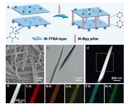
The fluorinated pillar-layer [Ni(TFBA)(Bpy)]n MOFs with dual organic ligands (TFBA and Bpy) were constructed via a facile room-temperature solution reaction for different times (2, 24, 48 and 72 h). In the structures of MOFs, TFBA ligands link Ni2+ to form 2D Ni-TFBA layers, and then these 2D Ni-TFBA layers can be assembled by Bpy pillars along 1D direction to construct 3D porous pillar-layer [Ni(TFBA)(Bpy)]n MOFs (Fig. 1a). More importantly, the Ni-TFBA layer is surrounded by F-containing groups with high hydrophobicity, effectively improving the stability of pillar-layer MOF [22, 24]. Also, this type of pillar-layer MOF with the strong Ni-N coordination bonds formed by soft-acid Ni2+cations with Bpy soft organic ligand has better stability based on the HSAB principle, which are more attractive than hydrogen bonds or Ni-O coordination bonds (formed by soft-acid metal cations with carboxylic acid hard ligands) [25, 28]. The morphology of [Ni(TFBA)(Bpy)]n MOFs (2, 24, 48 and 72 h) was examined via SEM (scanning electron microscopy) and TEM (transmission electron microscopy). As observed in Figs. 1b and c, the as-obtained [Ni(TFBA)(Bpy)]n MOF (48 h) displays microrod-like with diameter of 200 nm. SEM images of [Ni(TFBA)(Bpy)]n MOFs (2 h, 24 h, and 72 h) are displayed in Fig. S1 (Supporting information), many non-uniform bulk crystals were observed for [Ni(TFBA)(Bpy)]n MOF (2 h). As the reaction time increased from 2 h to 24 h, part of the bulk MOFs were transformed into MOF microrods, and until increased to 48 h, the bulk MOFs were completely transformed into uniform MOF microrods. As the reaction time continued to increase to 72 h, the MOF microrods morphologies were damaged and their size increased. Subsequently, the HAADF-STEM (high-angle annular dark-field scanning TEM) and elemental mapping confirm that the uniform distribution of the C, N, O, F, and Ni species in the samples (Figs. 1d and e, Fig. S2 in Supporting information).

|
Download:
|
| Fig. 1. (a) Schematic representation of the synthesis of [Ni(TFBA)(Bpy)]n MOFs. (b) SEM image, (c) TEM image, (d, e) HAADF-STEM images and elemental mapping of C-K, N-K, O-K, F-K, and Ni-K of the as-prepared [Ni(TFBA)(Bpy)]n MOF microrods obtained after stirring 48 h. | |
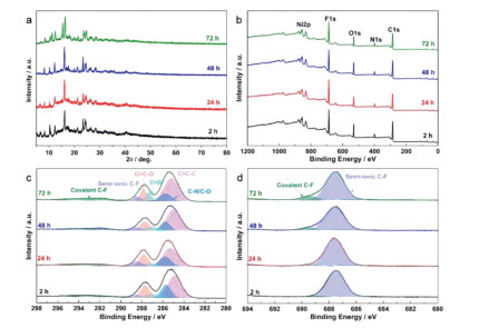
The crystalline phases and crystallinity of the as-obtained [Ni(TFBA)(Bpy)]n MOFs were studied through X-ray powder diffraction (XRD) technique. Fig. 2a reveals XRD patterns of [Ni(TFBA)(Bpy)]n MOFs, the diffraction patterns of which are in accord with a simulated pattern from the earlier reported single-crystal data (CCDC737134) [29, 30], confirming that [Ni(TFBA)(Bpy)]n MOFs were successfully synthesized. Also, [Ni(TFBA)(Bpy)]n MOFs (48 h) demonstrates good crystallinity. Fig. S3 (Supporting information) displays the Fourier Transform Infrared Spectroscopy (FTIR) spectra of [Ni(TFBA)(Bpy)]n MOFs, TFBA, and Bpy. The as-prepared [Ni(TFBA)(Bpy)]n MOFs present two peaks at 1372 and 1613 cm−1 belong to the symmetric and asymmetric stretching modes of coordinated –COO– groups, respectively, which is different from the bands of the –COOH group of the TFBA, suggesting that the monodentate coordination mode of the carboxyl group to the Ni2+. For Bpy, the characteristic bands at approximately 1587, 1482, and 1406 cm−1 result from C=C stretching of the benzene ring. The bands in the 800–1215 cm−1 range can be ascribed to aromatic C–H stretching vibrations. Also, [Ni(TFBA)(Bpy)]n MOFs reveal the characteristic adsorption peaks of the Bpy, indicating the existence of coordinate bonds between Ni2+ and Bpy ligand. In addition to the above, a new band at 629 cm−1 is associated with Ni-O that appears in [Ni(TFBA)(Bpy)]n MOFs. X-ray photoelectron spectroscopy (XPS) spectra of [Ni(TFBA)(Bpy)]n MOFs (Fig. 2b) shows the existence of Ni, N, F, O, and C in the samples. Fig. S4a (Supporting information) shows that the peaks of Ni 2p1/2 and Ni 2p3/2 are generated by the spin-orbit characteristics of Ni2+. The N 1s XPS peaks can be segmented into two peaks at 399.8 eV and 399.1 eV corresponding to Ni-N and pyridinic N (Fig. S4b in Supporting information) [31]. The fitted C 1s spectrums of the samples are shown in Fig. 2c, and the peak located at 285.0, 285.7, 287.2, 287.7, 288.5 and 292.8 eV can be assigned to C=C-C, C–N/C-O, C=O, O=C–O, semi-ionic C-F, and covalent C-F, respectively [32, 33]. In addition, the presence of semi-ionic C-F (687.6 eV) and covalent C-F (689.5 eV) species is further verified by the F 1s spectra (Fig. 2d) [34]. Meanwhile, the O 1s spectra also confirmed the presence of C=O (530.9 eV) and O=C–O (531.8 eV) species (Fig. S4c in Supporting information) [33].

|
Download:
|
| Fig. 2. (a) XRD patterns, and XPS spectra of [Ni(TFBA)(Bpy)]n MOFs obtained from different reaction times: (b) survey, (c) C 1s and (d) F 1s. | |
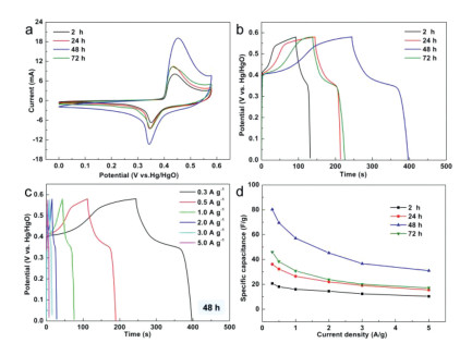
The electrochemical behaviors of the as-prepared [Ni(TFBA)(Bpy)]n MOFs were studied by three-electrode system in 3 mol/L KOH. Fig. S5 (Supporting information) shows cyclic voltammetry (CV) and galvanostatic charge-discharge (GCD) curves for the [Ni(TFBA)(Bpy)]n MOF (48 h) electrode with different potentials ranging from 0.0 to 0.52 V to 0.0–0.61 V, which exhibit the electrode has the highest specific capacitance at 0.58 V. The comparative CV curves of the four electrodes at 0.58 V recorded at 30 mV/s display each electrode has a couple of redox peaks, manifesting a typical reversible faradaic redox reactions of nickel ions, revealing the battery-type behaviors (Fig. 3a). Furthermore, [Ni(TFBA)(Bpy)]n MOF (48 h) electrode has a much larger integral CV curve area than other three electrodes, indicating the remarkably enhanced electrochemical activity. This fact is also confirmed via GCD measurements at 0.3 A/g (Fig. 3b), where the [Ni(TFBA)(Bpy)]n MOF (48 h) electrode reveals the longest discharge time. Also, the specific capacitance can be calculated from the GCD curves in Fig. 3c, and the corresponding results are exhibited in Fig. 3d, with the data of other electrodes included for comparison (Fig. S6 in Supporting information). Notably, the [Ni(TFBA)(Bpy)]n MOF (48 h) electrode delivers a specific capacitance of 80.2 F/g at 0.3 A/g, which is much higher compared to other three electrodes. The specific capacitance can remain a value of 31 F/g at 5 A/g, reflecting good rate properties.

|
Download:
|
| Fig. 3. (a) CV curves at 30 mV/s, (b) GCD curves at 0.3 A/g and (d) specific capacitance at various current densities for the as-prepared [Ni(TFBA)(Bpy)]n MOFs obtained from different reaction times in a three-electrode cell. (c) GCD curves of the as-prepared [Ni(TFBA)(Bpy)]n MOF (48 h) at different current densities. | |
The electrochemical reaction kinetics of [Ni(TFBA)(Bpy)]n MOF (48 h) electrode was explored on the basis of CV curves with different scan rates. As illustrated in Fig. S7a (Supporting information), at a scan rate as high as 100 mV/s, the redox peaks can be clearly observed, manifesting excellent capacitive behavior and good rate properties. Fig. S7b (Supporting information) shows that the b values of peak 1 and peak 2 are 0.53 and 0.62, respectively, which are near to 0.5, representing that the [Ni(TFBA)(Bpy)]n MOF (48 h) electrode is mainly at the mercy of the diffusion-controlled battery-type behavior [35, 36]. As shown in Fig. S7c (Supporting information), it is indicated that at 30 mV/s, the capacitive contribution accounts for approximately 60.6% of the total capacity. With increasing scan rates, the capacitive contribution ratio of [Ni(TFBA)(Bpy)]n MOF (48 h) electrode gradually increases from 38.7% to 90.9% (Figs. S7d and S8 in Supporting information), indicating that the electrode has satisfactory charge-transfer kinetics, which could account for its high rate capability [37, 38]. In addition, the storage kinetic processes of other electrodes were also investigated, and the results are shown in Figs. S7e and S9–S14 (Supporting information). The b values of all electrodes are close to 0.5, implying the corresponding redox reactions are mainly diffusion-controlled processes. The percent of the diffusion-controlled capacity contribution at different scan rates for the as-prepared [Ni(TFBA)(Bpy)]n MOFs are given in Fig. S7f (Supporting information), and the results show that [Ni(TFBA)(Bpy)]n MOF (48 h) has a much higher diffusion-controlled capacity contribution ratio compared with other electrodes, implying effective surface charge storage of the electrode. To further explore the charge transfer kinetics, electrochemical impedance spectroscopy (EIS) test was executed, and the gained Nyquist plots of [Ni(TFBA)(Bpy)]n MOFs are shown in Fig. S15 (Supporting information). It is apparent that the curve diameter of [Ni(TFBA)(Bpy)]n MOFs (48 h) is smaller than those of other three electrodes, that is, the electrode possesses the smallest charge transfer resistance (Rct) and fastest charge transport rate, which is of great significance for charge storage. The X-intercept in the high-frequency area belongs to the equivalent series resistance (Rs), which comes from the intrinsic resistance of the electrode and electrolyte. The [Ni(TFBA)(Bpy)]n MOFs (48 h) demonstrates a low value of Rs at 0.71 Ω, similar to 2 h (0.99 Ω), 24 h (0.86 Ω) and 72 h (0.57 Ω). This demonstrates the electrode has excellent electrochemical conductivity and rapid reaction kinetics.
To further demonstrate the practical application values of [Ni(TFBA)(Bpy)]n MOFs, the aqueous asymmetric supercapacitor (ASC) devices were assembled via using the [Ni(TFBA)(Bpy)]n MOFs and activated carbon (AC). The CV and GCD curves for the [Ni(TFBA)(Bpy)]n MOF (48 h)//AC device with different potentials varying from 0.0–1.55 V to 0.0–1.70 V, which indicate the device has the highest specific capacitance at 1.65 V (Fig. S16 in Supporting information). Consequently, the 0–1.65 V is chosen as the operating potential window and employed in the subsequent electrochemical tests. The CV curves of the assembled ASC devices at multiple scan rates with a working potential window of 0–1.65 V are displayed in Figs. S17a and S18 (Supporting information). The stable CV curves with no distinct shape change, indicating that ASC devices have a satisfactory reversibility. Fig. S17c (Supporting information) shows [Ni(TFBA)(Bpy)]n MOF (48 h)//AC device possess the longest discharge time compared to the other three ASC devices. The specific capacitance of all devices were calculated according to the GCD curves (Figs. S17b and S19 in Supporting information) and displayed in Fig. S17d (Supporting information). Obviously, the specific capacitance of [Ni(TFBA)(Bpy)]n MOF (48 h)//AC device is much larger than other three devices, affording 49.7, 46.8, 39.9, 35.2 and 31.6 mF/cm2 at 1, 2, 3, 5 and 8 mA/cm2, respectively. Meanwhile, the Nyquist plots of all devices are shown in Fig. S20 (Supporting information), which exhibit [Ni(TFBA)(Bpy)]n MOF (48 h)//AC device has a smallest R of 0.93 Ω compared with other three devices, indicating the superior conduction ability. More importantly, the practicality of the device was tested by connecting two [Ni(TFBA)(Bpy)]n MOF (48 h)//AC devices in series to light a yellow LED light (Fig. S21 in Supporting information). In addition, a long-term cycling property measurement of 5000 cycles at 3 mA/cm2 was executed to confirm the stability of the [Ni(TFBA)(Bpy)]n MOF (48 h)//AC device (Fig. S17e in Supporting information). The specific capacitance of the device was maintained at 97.4% after 5000 cycles, and the coulombic efficiency was up to 84.6%, which demonstrates the well cycling stability superior to the majority of the recently reported MOF nanomaterials (Table S1 in Supporting information) [10, 39, 40].
The excellent electrochemical cycling properties of [Ni(TFBA)(Bpy)]n MOFs (48 h)//AC device may be due to the fact that the electrode material is MOF crystal material composed of fluorinated organic ligand TFBA, which generally has lower surface energy and surface tension, higher chemical stability and hydrophobicity. To confirm this, we have also synthesized non-fluorinated [Ni(benzoic acid)(4, 4′-bipyridine)]n ([Ni(BA)(Bpy)]n) MOFs for comparison. The SEM images, EDS mapping images, XRD pattern and IR pattern of the as-prepared [Ni(BA)(Bpy)]n MOFs were shown in Figs. S22-S25 (Supporting information), respectively. The results showed that [Ni(BA)(Bpy)]n MOFs were successfully synthesized. Furthermore, the electrochemical properties of the as-prepared [Ni(BA)(Bpy)]n MOFs were studied in a three-electrode cell. Fig. S26 (Supporting information) shows that [Ni(BA)(Bpy)]n electrode material has good electrochemical energy storage performance. At the same time, the electrochemical performance of [Ni(BA)(Bpy)]n MOFs//AC device was further evaluated (Fig. S27 in Supporting information). The GCD curves at 3 mA/cm2 and specific capacitance at different current densities show that the specific capacitance of [Ni(BA)(Bpy)]n MOFs//AC is slightly higher than [Ni(TFBA)(Bpy)]n MOFs//AC (Figs. 4a and b). This may be due to the enhanced hydrophobicity of MOF materials after fluorination, which affects the good infiltration of water system electrolyte and electrode, thus the capacitance is slightly lower than that of non-fluorinated MOFs. However, the cycle stability curves (Fig. 4c) show that the capacitance retention of [Ni(BA)(Bpy)]n MOFs//AC dropped to 68.5% after 5000 cycles, while the capacitance retention of [Ni(TFBA)(Bpy)]n MOFs//AC was as high as 97.4%. After fluorination, the cycling stability of MOF is greatly improved, and the previous speculation is verified. MOFs composed of fluorinated organic ligands usually have low surface energy and surface tension, high chemical stability and hydrophobicity, which could be confirmed by the contact angles of 3 mol/L KOH droplets on the surface of [Ni(BA)(Bpy)]n and [Ni(TFBA)(Bpy)]n MOFs (Fig. 4d). The Nyquist plots of [Ni(TFBA)(Bpy)]n MOFs//AC and [Ni(BA)(Bpy)]n MOFs//AC devices are shown in Fig. S28 (Supporting information), which exhibit [Ni(TFBA)(Bpy)]n MOF//AC device has a smaller Rs compared with [Ni(BA)(Bpy)]n MOFs//AC device, indicating the good electrical conductivity.

|
Download:
|
| Fig. 4. (a) GCD curves at 3 mA/cm2, (b) specific capacitance at various current densities and (c) cycling ability at 3 mA/cm2 for 5000 cycles for [Ni(TFBA)(Bpy)]n MOFs//AC and [Ni(BA)(Bpy)]n MOFs//AC devices. (d) Contact angles of 3 mol/L KOH droplets on the surface of [Ni(BA)(Bpy)]n and [Ni(TFBA)(Bpy)]n MOFs. | |
In conclusion, we have prepared a series of the fluorinated pillared-layer [Ni(TFBA)(Bpy)]n MOF materials via a simple room-temperature solution reaction. With the increase of reaction time, the morphology of [Ni(TFBA)(Bpy)]n MOF materials transformed from bulk to uniform microrods. Using the [Ni(TFBA)(Bpy)]n MOF microrods as electrode for supercapacitor, the specifc capacitance reaches 80.2 F/g at 0.3 A/g, which is four times as large as bulk MOF, which can be explained by the short ion diffusion length from the microrod structure. More remarkably, after fluorination, the cyclic performance of MOF has been greatly improved. After 5000 cycles, the non-fluorinated [Ni(BA)(Bpy)]n MOFs showed a capacitance retention of only 68.5%, while the fluorinated [Ni(TFBA)(Bpy)]n MOFs had a high cycling ability with more than 97.4% capacitance retention at 3 mA/cm2. This work not only offers a significant method to control the morphology structure of MOFs, but also points out a promising direction for developing electrode materials with good cyclic stability.
Declaration of competing interestThe authors declare that they have no known competing financial interests or personal relationships that could have appeared to influence the work reported in this paper.
AcknowledgmentsThis work was supported by the National Natural Science Foundation of China (No. U1904215), the Top-notch Academic Programs Project of Jiangsu Higher Education Institutions (TAPP), and Natural Science Foundation of Jiangsu Province (No. BK20200044). Excellent doctoral dissertation of Yangzhou University and the Postgraduate Research & Practice Innovation Program of Jiangsu Province (No. KYCX19_2099). We also acknowledge the Priority Academic Program Development of Jiangsu Higher Education Institutions.
Supplementary materialsSupplementary material associated with this article can be found, in the online version, at doi:10.1016/j.cclet.2021.05.010.
| [1] |
Z. Jiang, X. Xu, Y. Ma, et al., Nature 586 (2020) 549-554. DOI:10.1038/s41586-020-2738-2 |
| [2] |
X. Li, X. Yang, H. Xue, H. Pang, Q. Xu, EnergyChem 2 (2020) 100027. DOI:10.1016/j.enchem.2020.100027 |
| [3] |
T. Qiu, S. Gao, Z. Liang, et al., Angew. Chem. Int. Ed. (2021). DOI:10.1002/anie.202012699 |
| [4] |
D. Li, H.Q. Xu, L. Jiao, H.L. Jiang, EnergyChem 1 (2019) 100005. DOI:10.1016/j.enchem.2019.100005 |
| [5] |
C.C. Hou, H.F. Wang, C. Li, Q. Xu, Energy Environ. Sci. 13 (2020) 1658-1693. DOI:10.1039/C9EE04040D |
| [6] |
G. Yuan, S. Yu, J. Jie, et al., Chin. Chem. Lett. 31 (2020) 1941-1945. DOI:10.1016/j.cclet.2019.12.034 |
| [7] |
H. Jiang, X.C. Liu, Y. Wu, et al., Angew. Chem. Int. Ed. 130 (2018) 3980-3985. DOI:10.1002/ange.201712872 |
| [8] |
J. Gu, Y. Xu, Q. Li, H. Pang, Chin. Chem. Lett. 32 (2021) 2017-2020. DOI:10.1016/j.cclet.2020.11.066 |
| [9] |
S. Zheng, X. Li, B. Yan, et al., Adv. Energy Mater. 7 (2017) 1602733. DOI:10.1002/aenm.201602733 |
| [10] |
D. Sheberla, J.C. Bachman, J.S. Elias, et al., Nat. Mater. 16 (2017) 220-224. DOI:10.1038/nmat4766 |
| [11] |
Y. Li, Y. Shan, H. Pang, Chin. Chem. Lett. 31 (2020) 2280-2286. DOI:10.1016/j.cclet.2020.03.027 |
| [12] |
D.D. Zhou, X.W. Zhang, Z.W. Mo, et al., EnergyChem 1 (2019) 100016. DOI:10.1016/j.enchem.2019.100016 |
| [13] |
S. Zheng, Q. Li, H. Xue, H. Pang, Q. Xu, Natl. Sci. Rev. 7 (2020) 305-314. DOI:10.1093/nsr/nwz137 |
| [14] |
L. Wang, X. Feng, L. Ren, et al., J. Am. Chem. Soc. 137 (2015) 4920-4923. DOI:10.1021/jacs.5b01613 |
| [15] |
X.F. Lu, P.Q. Liao, J.W. Wang, et al., J. Am. Chem. Soc. 138 (2016) 8336-8339. DOI:10.1021/jacs.6b03125 |
| [16] |
S. Zheng, Y. Zheng, H. Xue, H. Pang, Chem. Eng. J. 395 (2020) 125166. DOI:10.1016/j.cej.2020.125166 |
| [17] |
S. Zhao, Y. Wang, J. Dong, et al., Nat. Energy 1 (2016) 16184. DOI:10.1038/nenergy.2016.184 |
| [18] |
H. Guo, Y. Zhu, S. Wang, et al., Chem. Mater. 24 (2012) 444-450. DOI:10.1021/cm202593h |
| [19] |
X. Xiao, L. Zou, H. Pang, Q. Xu, Chem. Soc. Rev. 49 (2020) 301-331. DOI:10.1039/C7CS00614D |
| [20] |
M. Zhao, Y. Huang, Y. Peng, et al., Chem. Soc. Rev. 47 (2018) 6267-6295. DOI:10.1039/C8CS00268A |
| [21] |
D.D. Zhou, P. Chen, C. Wang, et al., Nat. Mater. 18 (2019) 994-998. DOI:10.1038/s41563-019-0427-z |
| [22] |
C. Wang, D.D. Zhou, Y.W. Gan, et al., Natl. Sci. Rev. (2020) 1-9. |
| [23] |
C. Wang, J. Huang, R.K. Huang, et al., Inorg. Chem. 58 (2019) 3944-3949. DOI:10.1021/acs.inorgchem.9b00006 |
| [24] |
A. Cadiau, Y. Belmabkhout, K. Adil, et al., Science 356 (2017) 731-735. DOI:10.1126/science.aam8310 |
| [25] |
J. Huang, Y. Li, R.K. Huang, et al., Angew. Chem. Int. Ed. 57 (2018) 4632-4636. DOI:10.1002/anie.201801029 |
| [26] |
L. Li, J.D. Yi, Z.B. Fang, et al., Chem. Mater. 31 (2019) 7584-7589. DOI:10.1021/acs.chemmater.9b02375 |
| [27] |
R.G. Pearson, J. Am. Chem. Soc. 85 (1963) 3533-3539. DOI:10.1021/ja00905a001 |
| [28] |
S. Yuan, L. Feng, K. Wang, et al., Adv. Mater. 30 (2018) 1-35. |
| [29] |
Z. Hulvey, E. Ayala, A.K. Cheetham, Zeitschrift Für Anorg. Und Allg. Chem. 635 (2009) 1753-1757. DOI:10.1002/zaac.200900312 |
| [30] |
C. Shi, X. Wang, Y. Gao, et al., J. Solid State Electrochem. 21 (2017) 2415-2423. DOI:10.1007/s10008-017-3591-6 |
| [31] |
X. Zhang, S. Liu, Y. Zang, et al., Nano Energy 30 (2016) 93-102. DOI:10.1016/j.nanoen.2016.09.040 |
| [32] |
S. Huang, Y. Li, Y. Feng, et al., J. Mater. Chem. A 3 (2015) 23095-23105. DOI:10.1039/C5TA06012E |
| [33] |
S. Liu, X. Zhang, G. Wang, Y. Zhang, H. Zhang, ACS Appl. Mater. Interfaces 9 (2017) 34269-34278. DOI:10.1021/acsami.7b11101 |
| [34] |
F. Zhou, H. Huang, C. Xiao, et al., J. Am. Chem. Soc. 140 (2018) 8198-8205. DOI:10.1021/jacs.8b03235 |
| [35] |
V. Augustyn, J. Come, M.A. Lowe, et al., Nat. Mater. 12 (2013) 518-522. DOI:10.1038/nmat3601 |
| [36] |
Q. Wang, Y. Luo, R. Hou, et al., Adv. Mater. 31 (2019) 1905744. DOI:10.1002/adma.201905744 |
| [37] |
J. Huang, Y. Xiong, Z. Peng, et al., ACS Nano 14 (2020) 14201-14211. DOI:10.1021/acsnano.0c07326 |
| [38] |
B. Fei, Z. Yao, D. Cai, et al., Energy Storage Mater. 25 (2020) 105-113. DOI:10.1016/j.ensm.2019.10.025 |
| [39] |
J. Yang, C. Zheng, P. Xiong, Y. Li, M. Wei, J. Mater. Chem. A 2 (2014) 19005-19010. DOI:10.1039/C4TA04346D |
| [40] |
C. Qu, Y. Jiao, B. Zhao, et al., Nano Energy 26 (2016) 66-73. DOI:10.1016/j.nanoen.2016.04.003 |