 2021, Vol. 32


b College of Chemical Engineering, Zhejiang University of Technology, Hangzhou 310014, China;
c College of Chemistry and Molecular Engineering, Zhengzhou University, Zhengzhou 450001, China
Supercapacitors, as one type of representative energy-storage devices, operate through reversible charge separation to form an electric double layer at each cathode/anode interface with no redox reaction occurred in the entire charging/discharging process, thus possessing the preponderances like high power density and long cycle life compared with batteries [1-6]. However, the energy density of traditional aqueous supercapacitors is limited to low level, as free water molecules in dilute electrolyte lead to the narrow electrochemical stability window [7, 8]. Superconcentrated water-in-salt electrolytes with high salt/water mass ratios (above 1), emerge as wide-voltage aqueous media because of the minimized relative contents and electrochemical activities of free water [9, 10]. The easy-to-handle assembly of water-in-salt electrolytes also needs no strict water/oxygen-free conditions required in moisture-sensitive nonaqueous systems [11, 12]. Nevertheless, the employment of such superconcentrated ion-rich systems usually brings in insufficient electrolyte-electrode interface caused by salt precipitation tendency and sluggish charge transfer owing to the strong electrostatic cation/anion attractions [13, 14]. Regarding this, porous carbon electrodes with high surface areas and balanced pore architectures are proposed to pave the vast working interface to allow more ion-adsorbing sites for efficient charge storage.
From the perspective of sustainable development, seeking for eco-friendly carbon precursors, coupled with exploiting straightforward yet economic syntheses, becomes essential for the fabrication of porous carbon nanomaterials. Among them, biomass (e.g., cabbage leaf, corn grain, fish skin, peanut dreg) is frequently applied as raw materials or bio-templates by virtues of high cost-effective, easy-to-obtain and environmentally friendly features [15-17]. Using eucalyptus tree sawdust as carbon supply, Sevilla's group employed a KHCO3 activation strategy to obtain highly microporous carbons with extremely high specific surface area of 2950 m2/g, and good capacitive performances were realized in aqueous (258 F/g at 0.2 A/g, 1 mol/L H2SO4) and organic electrolytes-loaded supercapacitors (170 F/g at 1 A/g, TEABF4) [17]. However, the pristine pore size distributions of biomass-derived carbons cannot always be well regulated through simple thermal treatments [18]. Likewise, synthetic organic polymers as another mainstream carbon supplies, also tend to aggregate into large pieces and end-died pores during direct thermal conversion, and post activation treatment of these materials can merely punch the limited pores exposed on the surface of bulk carbon aggregates [19-22].
The nanocasting of interpenetrating polymer networks (IPNs) gives a promising self-template strategy that combines two or more polymer networks with each other by physically interlacing/knitting forces instead of chemical network linkage [23, 24]. Molecule-level interlaced networks offer a compulsive strategy for mixing these otherwise immiscible networks together, thus, some inherited and even synergetic properties of single networks may be equipped in IPNs [25, 26]. Additionally, the macrophase separation between the exerted porogen and carbon supply can be restricted during pyrolyzing [27-29]. In the pyrolysis process, the polymer network with relatively high thermostability functions as carbon supply, while the other relatively thermolabile one is mainly decomposed into volatile fragments to undertake the self-porogen role [29]. Thus, high controlled tunability in porous carbon fabrication is expected to be accomplished by IPN-inspired strategies through endless couples of versatile polymer networks.
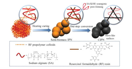
In this work, we report the fabrication of porous carbon electrodes via one-step thermochemical conversion of semi-biomass IPN blend consisting of the sodium alginate (SA) bio-polymer network and the resorcinol-formaldehyde (RF) resin skeleton. During pyrolyzing, the high crosslinked RF network in IPN functions as carbon supply owing to good thermostability, while molecule-level knitting forces between two polymeric networks efficiently relieve the skeleton shrinkage and/or macrophase separation issues. As a natural biomacromolecule, the secondary relatively thermolabile SA network is connected by β-1, 4-glycosidic bonds with a carboxyl group on each repeating unit, which can sacrifice itself at elevated temperature to promote the porosity and morphology refinement due to the uniform KOH punching throughout the IPN network. The IPN pyrolyzed at an optimal temperature of 600 ℃, obtains the moss-like globule surfaces and interconnected porous architecture for high accessible surface area (1013 m2/g) to allow high-efficiency ion transport and adsorption. Therefore, the electrochemical responses are reached with the specific capacity of 312 and 202 F/g under 1 and 20 A/g in the three-electrode system applying KOH electrolyte. Moreover, taking the advantage of 9 mol/kg NaClO4 cosolvent-in-salt electrolyte, the voltage window is extended to 2.4 V, thus giving a high energy delivery of 32.3 Wh/kg at the power output of 240 W/kg with satisfactory cycling tolerance (capacitance retention of 90.3%) over 10, 000 successive turns.
Fig. 1 illustrates the synthesis route of carbon materials CIPNs (denoted as CIPN-x, where x refers to the mass ratio of sodium alginate to resorcinol) based on semi-biomass IPNs consisting of resorcinol-formaldehyde (RF) resin and biomass sodium alginate (SA). In this strategy, RF prepolymer colloids initially diffuse into the pre-existing SA polymeric network, and further heating curing leads to the molecule-level knitting of SA chains in the highly crosslinked RF network for the final precursor IPNs. During the one-step synergistic conversion at 600 ℃, the in-knitted SA chains in IPN offer intrusive and dispersed etching spaces to accommodate KOH, and then the IPN/KOH mixture goes through the alkali corrosion (6KOH + 2C ⟶ 2K + 3H2 + 2K2CO3) to finally obtain pore channels [30]. Comparatively, the carbonized RF/SA (CRF/CSA) are synthesized under the similar CIPN-0.25 recipe without SA/RF addition. FT-IR spectra (Fig. S2a in Supporting information) characterize the coexistence of two polymeric networks in the typical IPN. SA and IPN-0.25 exhibit the peak of C-H and -CO2- at 2923 and 1596 cm-1, respectively [31], while the -CH2 peak at 1460 cm-1 for RF can also be found in IPN-0.25 [32]. Additionally, the mutual board band at 3350 cm-1 corresponds to the -OH in IPN-0.25 and parent SA/RF. As shown in TGA profiles (Fig. S2b in Supporting information), the carbon yields of IPN-0.25 and parent SA, RF are 60.7%, 36.6%, 64.6% at 600 ℃, respectively. During pyrolyzing, the highly cross-linked RF network gradually converts into carbon skeleton relying on good thermal stability, and the intermediate yield of IPN-0.25 indicates the successful fabrication of semi-biomass IPN consisting of carbon-rich RF resin and decomposable biomass SA. On account of the decarboxylation reaction started at 242 ℃ and the subsequent mass loss associated with gradual chain decomposition (e.g., glycosidic bond, β-D-mannuronic), the relatively thermolabile porogen role of the secondary SA network in IPN is verified [33]. The XPS spectra of carbon materials (Fig. S2c in Supporting information) with the similar elemental compositions of CIPN-0.25 (84.24/15.76 at% for C/O) and CRF (84.48/15.52 at% for C/O) further demonstrate that most of relatively thermolabile SA sacrifices as the in-knitted bio-porogen at elevated temperature to leave behind porous textures during KOH-assisted pyrolyzing. Molecule-level interlacing forces in such IPNs can encourage two incompatible polymeric networks to closely interpenetrate/blend into an integrated polymeric network, by which the skeleton shrinkage and/or the porogen macrophase separation under pyrolyzing is restrained [34]. By regulating blending proportions of the sacrificial SA network in IPNs, flexible control over pore architectures is realized, and meanwhile dispersed SA network facilitates KOH etching for reinforced structural refinement.

|
Download:
|
| Fig. 1. Schematic synthesis route of CIPNs based on semi-biomass IPNs. | |
The nitrogen sorption isotherm of CIPN-0.25 (Fig. 2a) combines the characteristics of the type I and IV isotherms [35]. A rapid rise at P/P0 < 0.05 and the hysteresis loop in the medium-pressure region indicate the coexistence of plentiful micro-, meso- and macropores [36, 37], and the highest absorptive amount for CIPN-0.25 among the three materials discloses the well-developed porosity in the IPNs-derived carbon material. As observed from pore size distribution curves (Fig. 2b), CIPN-0.25 shares the similar pore diameters distributed at 0.54 and 1.3 nm in the microporous region and a wide range of 2–30 nm in the mesoporous region with CRF. In contrast, CSA displays a quite different type I isotherm with no distinctive hysteresis loop, suggesting that the SA network rarely participates in the carbon skeleton rearrangement at high temperature [38, 39]. As the SA proportion in IPN increases from 0.125 to 0.25, the surface area displays a slight downward trend from 1047 m2/g to 1013 m2/g owing to the pore diameter enlargement induced by SA decomposition, and the Vmicro/Vtotal value consistently decreases (Figs. 2c and d, Table S1 in Supporting information). Additionally, excessive SA proportion in IPN could sharply reduce the cross-linking density of the carbon supply, and thus the KOH etching into the flimsy skeleton causes the decayed surface areas and total pore volumes (CIPN-1, 889 m2/g and 0.65 cm3/g). The SA decarboxylation results in a preliminary porous frame along with the subsequent chain decomposition (e.g., glycosidic bond, β-D-mannuronic) in the initial stage of pyrolyzing, and these resultant nanopores offer intrusive and dispersed etching spaces to accommodate KOH during further programed pyrolyzing for pore structure refinement [33, 40]. For comparison, the pore structure information of CIPN-0.25A0 (the carbon prepared without KOH, CIPN-0.25Ay, where y refers to the mass ratio of activator to IPN precursors) is displayed to further clarify the effect of SA in IPN as an in-knitted synergistic porogen. CIPN-0.25A0 owns the surface area of 625 m2/g and multilevel pore distribution centered at 0.54, 1.3 and 2–11 nm (Figs. S3a, b and Table S1 in Supporting information), demonstrating the preliminary pore-forming effect of relatively thermolabile SA. Among the CIPN-0.25, CIPN-0.25A0 and CRF, CIPN-0.25 owns the obviously enhanced micropore (centered at 0.54 nm) quantity as well as the enlarged mesopore quantity and diameter compared with the other two carbon samples. Accordingly, owing to the SA/KOH synergistic pore-forming effect, both the specific surface area and total pore volume are increased to 1013 m2/g and 0.96 cm3/g for CIPN-0.25, while CIPN-0.25A0/CRF prepared with the absence of KOH/SA only owns the surface area of 625/620 m2/g (Figs. S3a and b, Table S1). Furthermore, the KOH dosage also determines the etching degree into the IPNs skeleton and plays an importance influence on the porous structure evolution. As disclosed in Figs. S3c, d and Table S1 (Supporting information), CIPN-0.25A0.5 prepared under an insufficient activator dosage possesses an unsatisfactory surface area (855 m2/g) and an undeveloped porosity with tiny mesopores, while the KOH overdose brings about the meso-/macropore collapse or micropore disappearance in CIPN-0.25A2 and CIPN-0.25A3. The influence of pyrolysis conditions including the temperature, time and heating rate is also investigated (Figs. S3e and f, Table S1 in Supporting information). An optimal pyrolysis temperature of 600 ℃ can reach the large specific surface area of 1013 m2/g and balanced micro-/mesopore distribution (Vmicro/Vtotal = 31.3%), while inadequate/overmuch pyrolysis at 550/650 ℃ leads to the surface area of 859/914 m2/g and decayed Vmicro/Vtotal values. Meanwhile, the obtained carbon materials prepared at the same temperature of 600 ℃ and the different pyrolysis time of 4 h (CIPN-0.25PT4) or heating rate of 1.5 ℃/min (CIPN-0.25HR1.5) share the similar nitrogen sorption isotherms and pore size distributions with CIPN-0.25, demonstrating the suitable setup of the programed pyrolysis. Additionally, Raman spectra (Fig. S4 in Supporting information) reveal the graphitization degree (ID/IG) ranging from 0.78 to 0.92, wherein the graphitization degree displays a slight uptrend with the increasing pyrolysis temperature. From the above, the high surface area of CIPN-0.25 is assigned to the optimized cross-linking density of two blended networks in IPN, and the optimization of preparation conditions further gives CIPN-0.25 with the well-developed hierarchical porosity and satisfactory graphitization degree.

|
Download:
|
| Fig. 2. (a, c) Nitrogen sorption isotherms and (b, d) pore size distribution curves of CIPNs, CRF and CSA. | |
As the SA proportion in IPN increases from 0.125 to 1, the morphology of IPN transforms from block solids to globule-like topographies, and then the mean diameter of globule-like particles continues to shrink to 1 µm (Figs. S5a-d in Supporting information). The morphology evolution by the increasing amount of SA knitted into the IPN can be explained that the phenolic hydroxyl groups in the RF network form hydrogen bonds with the carboxyl and hydroxyl groups in SA, and consequently the block solids are split into globule-like particles [41-43]. Upon one-step synergistic conversion at 600 ℃, the typical sample of CIPN-0.25 demonstrates a hemi-split globules morphology with moss-like surfaces from SEM images (Figs. 3b, e, f). The TEM images (Figs. 3g and h) reveal the interconnected porous architecture with the hierarchical porosity consisting of micro-, meso- and macropores aroused by the SA/KOH synergistic pore-forming effect throughout the IPN network. In contrast, the SEM image (Fig. S5j in Supporting information) of CSA presents a block morphology, and the TEM image (Fig. S5k in Supporting information) discloses the microporous structure. During the high temperature conversion, the carbonized products prepared at the relatively low SA proportion retain the original morphologies well. CIPN-0.125 appears a macroporous block morphology (Fig. 3a) that is similar to CRF (Fig. S5i in Supporting information), and CIPN-0.25 shows a porous hemi-split globules geometry with moss-like surfaces (Fig. 3b). However, the morphology inconsistence between precursor/carbons by further SA increase in IPNs can be explained that the decayed crosslinking degree of the precursor network induced by relatively thermolabile SA leads to the collapse of original frameworks during high-temperature KOH etching (Figs. 3c and d). Besides, CIPN-0.25A0 and CIPN-0.25A0.5 (Figs. S5e and f in Supporting information) that prepared with no/insufficient activator can maintain the original morphology of precursor well, while overmuch KOH etching causes a tendency of collapsing and fragmenting in CIPN-0.25A2 and CIPN-0.25A3 (Figs. S5g and h in Supporting information). Overall, the unique porous hemi-split globules shape with moss-like surfaces can be attributed to suitable amount of activator and component proportion.

|
Download:
|
| Fig. 3. SEM images of (a) CIPN-0.125, (b) CIPN-0.25, (c) CIPN-0.5, (d) CIPN-1. (e, f) SEM, (g, h) TEM images of CIPN-0.25. | |
Taking the above discussion together, during one-step thermochemical conversion, the highly cross-linked RF network gradually converts into carbon skeleton relying on good thermal stability, where the SA/KOH synergistic pore-forming effect can be summarized as follows: (ⅰ) the SA decarboxylation results in a preliminary porous frame along with the subsequent chain decomposition (e.g., glycosidic bond, β-D-mannuronic) in the initial stage of pyrolyzing [44]; (ⅱ) the in-knitted SA chains in IPN offer intrusive and dispersed etching spaces to accommodate KOH during further programed pyrolyzing, and finally the interconnected multilevel porous architecture and a large accessible electrode surface are obtained [33, 40]; (ⅲ) as a morphology-directing agent, SA with the carboxyl and hydroxyl groups forms hydrogen bonds with the phenolic hydroxyl groups in RF, and consequently the block solids are split into globule-like particles [41-43].
To evaluate electrochemical properties of CIPNs, CRF and CSA, the three-electrode system is employed using 6 mol/L KOH as electrolyte under the voltage window of -1~0 V. CV profiles (Figs. 4a and b) of all the samples demonstrate a rectangle-like shape exclusive to electric double-layer capacitors [45]. According to the GCD curve (Figs. 4c and d), CIPN-0.25 has the best specific capacitance of 312 F/g at 1 A/g, outperforming those of CRF (179 F/g) and CSA (70 F/g) synthesized from the single precursor network, other CIPNs fabricated at different SA/RF blending proportions (from 262 F/g to 302 F/g) and varying activator mass ratios (from 224 F/g to 283 F/g). The relatively high surface area (1013 m2/g) for CIPN-0.25 can expose rich ion absorption sites for charge accumulation in electric double-layer, hence giving the superior capacitive performance among carbon samples [46, 47]. Additionally, the slightly decayed specific capacitance of CIPN-0.125 with higher surface area (290 F/g and 1047 m2/g) can be explained that the increasing SA proportion in IPNs favors the uniform SA/KOH synergistic pore-forming to increase surface accessibility by interconnected pore channels. Compared with CIPN-0.125 with a slightly higher surface area of 1047 m2/g, balanced micro-/mesopore distribution (Vmicro/Vtotal = 31.3%) in CIPN-0.25 offers interconnected mesopore highways to boost the pore accessibility/electrolyte transfer, contributing to the obviously increased capacitive performances for CIPN-0.25. The EIS test is applied for the in-depth investigation into the ion/electron transfer dynamics within IPN-derived porous architectures. The Nyquist plots (Fig. 4e) verify that the equivalent series resistance (Rs) of CIPN-0.25 is only 0.34 Ω and the small semicircle diameter represents a very low charge-transfer resistance (Rct, 0.36 Ω), together with a small Warburg resistance (W, 0.45 Ω). In contrast, CRF has a slightly smaller W of 0.38 Ω, but the low CRF surface limits the charge transfer process, leading to the poor dynamics (Rct = 0.67 Ω).

|
Download:
|
| Fig. 4. Electrochemical behaviors in a three-electrode system using 6 mol/L KOH electrolyte solution: (a) CV curves at 10 mV/s of CRF, CIPN-0.25 and CSA electrodes and (b) CIPNs with different proportion and mass ratio of activator. (c) GCD curves at 1 A/g of CRF, CIPN-0.25 and CSA electrodes and (d) CIPNs with different proportion and mass ratio of activator. (e) Nyquist plots. (f) Specific capacitances at different current densities of CRF, CSA and CIPNs electrodes. (g) The comparison chart of the six parameters of CRF, CIPN-0.25 and CSA electrodes and (h) CIPNs with different proportion and (i) mass ratio of activator. | |
The fast charge propagation and ion transportation of CIPN-0.25 can be attributed to the following integrated advantages of structure and morphology: (ⅰ) hierarchical porosity caused by the uniform KOH punching throughout the IPN network offers shortened ion diffusion distance and mass resistance for direct transportation into the carbon interface through interconnected pore tunnels [16, 48]; (ⅱ) the decreased particle size creates more contacting points on the electrode surface for continuous supplement of electrolyte ions, and unique moss-like globule surfaces also enrich exposed edges for improved interfacial charge storage [49, 50]. Correspondingly, CIPN-0.25 present a high-rate performance of 192 F/g (61.5%) under 20 A/g in comparison to CRF (34.1%), CSA (57.1%) and other CIPNs (56.9%–60.1%) (Fig. 4f). The oxygen doping in CIPN-0.25 results in the small contact angles of 53° with 6 mol/L KOH and 18° with 9 mol/kg NaClO4 complex-solvent electrolyte (Fig. S6 in Supporting information), demonstrating the enhanced surface affinity towards electrolyte media. The higher surface affinity towards the 9 mol/kg NaClO4 complex-solvent electrolyte should be attributed to the reduced surface tension in the acetonitrile solution [51]. The optimum SA proportion and activator ratio endow CIPN-0.25 with the largest accessible surface area and balanced pore architecture to facilitate ion adsorption and charge transfer, thus, exhibiting the reasonable impedance (Rs, Rct and W) and the highest capacitive performance among sample electrodes (Figs. 4g–i).
Electrochemical characters of CIPN-0.25 are further evaluated in the two-electrode system devices using and NaClO4 electrolyte solutions under the voltage window of 0–2.2 V. CV curves and Nyquist plots (Figs. S7a and b in Supporting information) reveal the good electric double-layer capacitor properties with a small internal resistance, even in the high-concentrated water-in-salt electrolytes. The rapid ion diffusion and fast charge propagation can be attributed to the superior porous texture with interconnected channels of micro, meso and macropores [52]. As the concentration of NaClO4 increases from 5 mol/kg to 17 mol/kg, the CIPN-0.25-loaded device can endure the electrolytes of different viscosities and exhibits the highest specific capacitance in the 9 mol/kg NaClO4 at 1 A/g (Fig. S7c in Supporting information). The CIPN-0.25-loaded device also performs well in the high current charge-discharge test and rate performance measurements, exhibiting high energy output of 24.0 Wh/kg (at 220 W/kg) and good reversibility, respectively (Figs. S7d and e in Supporting information). After 10, 000 continuous charge-discharge cycles at 1 A/g, the device still has a retention capacity of 88.4% (Fig. S7f in Supporting information). The excellent charge storage performance of CIPN-0.25 in 9 mol/kg NaClO4 indicates that the porous carbon globules can withstand viscous ultra-high concentrations water-in-salt electrolyte at high voltage through its high specific surface area accessibility, which rely on its moss-like morphology, small particle size and interconnected hierarchical pore structure. Therefore, the temperature-dependent tests are further carried out to verify the adaptability in practical energy storage. As the operating temperature of the device rises from 0 ℃ to 80 ℃, the integral area of the CV curve and the charge/discharge time of the GCD curve (Figs. S8a and b in Supporting information) both demonstrate an upward tendency. Due to the increased ionic conductivity and accelerated transfer of ions from the electrolyte to the electrode, the capacitance of the device at 80 ℃ is slightly improved (about 6%) compared to that at 0 ℃. Additionally, as the temperature increases, the Rs value of the supercapacitor decreases, which indicates the increased temperature promotes the diffusion and transport of electrolyte ions (Fig. S8c in Supporting information). Moreover, Fig. S8d (Supporting information) exhibits the cycle performance of the device for 10 cycles at each temperature from 0 ℃ to 80 ℃, maintaining a stable capacity and working normally to power a LED (light emitting diode). After performing the high temperature measurement, the energy storage of the device reversibly recovers to the initial capacitance at 0 ℃, and the attenuation is almost negligible, which demonstrates a wide range of applicable operating temperature and excellent electrochemical reversibility.
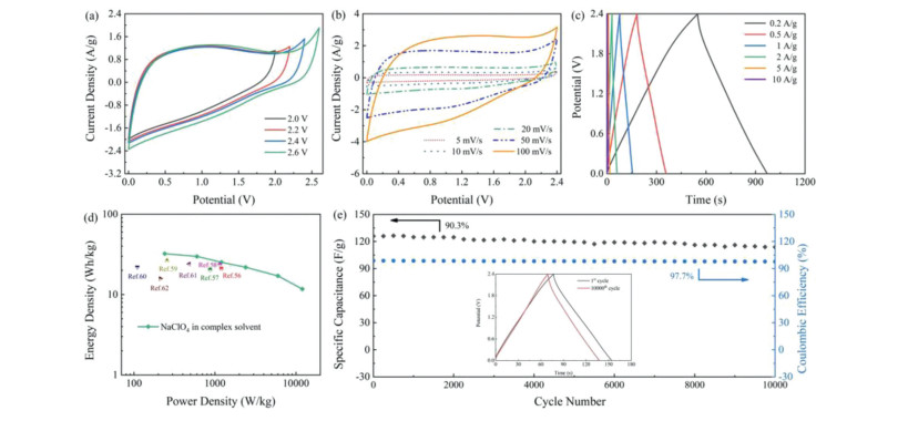
The CIPN-0.25-loaded two-electrode device is further carried out with 9 mol/kg NaClO4 in complex solvent electrolyte. Water-in-salt electrolytes have been reported to suppress water decomposition, and introduction of acetonitrile in the solution can further prevent the accumulation of free water at the electrode interface [53-55]. In this case, a combination of NaClO4, H2O and acetonitrile in an appropriate ratio can effectively regulate the ratio of water in free and water that interacts with sodium ion [51, 56], enabling the high working voltage up to 2.4 V (Figs. 5a and b). All the CV profiles display rectangle-like shapes with no redox signals, indicating that charge storage comes from the formation of double electrochemical interlayers in 9 mol/kg NaClO4 complex-solvent electrolyte even under a high operational voltage of 2.4 V. The GCD curve (Fig. 5c) just reveal a merely little voltage drop at such high voltage window, representing a typical electric double layer capacitor energy storage mechanism. The NaClO4-loaded device in complex solvent electrolyte endures the various current densities over ten cycles with a superb electrochemical capacity and cycling performance (Fig. S9a in Supporting information). The capacitance of the device is reversibly restored to its original value, indicating that supercapacitors using NaClO4 complex solvent electrolytes have high electrochemical recoverability. The Rct of NaClO4-loaded in complex solvent electrolyte (8.25 Ω) in Nyquist plots (Fig. S9b in Supporting information) is just slightly more obvious than that of aqueous NaClO4 (6.81 Ω). Significantly, NaClO4-loaded device in complex solvent electrolyte is able to express a high energy output up to 32.3 Wh/kg at 240 W/kg and 11.7 Wh/kg at 12 kW/kg, surpassing those of other carbon-based cells (Fig. 5d and Table S2 in Supporting information) [56-62]. Besides, the device exhibits excellent cycling stability by remaining 90.3% of its initial capacitance at 1 A/g with almost no coulombic efficiency drop after persistent 10, 000 cycles (Fig. 5e).

|
Download:
|
| Fig. 5. Electrochemical behaviors of CIPN-0.25 in a two-electrode system using 9 mol/kg NaClO4 complex solvent electrolyte: (a) CV curves at different voltage windows and (b) different scanning rates. (c) GCD curves at different current densities. (d) Ragone plots. (e) Cycling stability at 1 A/g. | |
Therefore, CIPN-0.25 synthesized via one-step thermochemical conversion of semi-biomass IPN exhibits efficient charge-storage behaviors, which can be assigned to the following structural and morphological efforts. First, the molecule-level knitted SA chains in IPN function as the bio-porogen under KOH etching to result in high surface area to allow plentiful ion-adsorbing sites for charge accumulation [62, 63]. Second, the SA/KOH synergistic pore-forming reinforces structural refinement, and thus the interconnected multilevel pore distribution further boosts the pore accessibility/electrolyte transfer even in sticky concentrated media [51, 56, 57, 64]. Finally, unique moss-like globule surfaces with decreased particle size expose more contacting points on the electrode surface for improved interfacial energy storage [49, 52].
In summary, the semi-biomass IPN derived porous carbon globules are fabricated via thermochemical conversion. The innovative design strategy of IPN precursor is demonstrated through physically knitting the SA bio-polymeric chains into the highly crosslinked RF network. Molecule-level interlacing networks efficiently prevent the shrinkage of RF skeleton when producing carbon, while the other SA network can address macrophase separation issue to function as a morphology-directing agent and sacrifice as an in-knitted porogen. As a result, porous carbon globules with moss-like surfaces are endowed synergetic pyrolyzing advantage of interconnected pore architecture for high accessible electrode surface (1013 m2/g). Thus, the efficient electrochemical responses are reached with the specific capacitance of 312 F/g at 1 A/g applying KOH electrolyte in three-electrode system. When pairing the high-performance CIPN-0.25 electrode with 9 mol/kg NaClO4 complex-solvent electrolyte, the voltage window is extended to 2.4 V and the device exhibits efficient energy storage of 32.3 Wh/kg at 240 W/kg. We believe that this semi-biomass IPN-based method can give people an inspiration to design novel precursor systems for functionalized porous carbons in target applications.
Declaration of competing interestThe authors declare that they have no known competing financial interests or personal relationships that could have appeared to influence the work reported in this paper.
AcknowledgmentsThis work is financially supported by the National Natural Science Foundation of China (Nos. 51772216, 21905207, 21875165 and 21703161), the Science and Technology Commission of Shanghai Municipality, China (Nos. 20ZR1460300, 14DZ2261100), Zhejiang Provincial Natural Science Foundation of China (No. LY19B010003), the Fundamental Research Funds for the Central Universities, and the Large Equipment Test Foundation of Tongji University.
Supplementary materialsSupplementary material associated with this article can be found, in the online version, at doi:10.1016/j.cclet.2021.04.055.
| [1] |
J. Du, L. Liu, Y. Yu, et al., Chin. Chem. Lett. 30 (2019) 1423-1427. DOI:10.1016/j.cclet.2019.03.004 |
| [2] |
C. Hu, M. Li, J. Qiu, et al., Chem. Soc. Rev. 48 (2019) 2315-2337. DOI:10.1039/C8CS00750K |
| [3] |
M. Mansuer, L. Miao, D. Zhu, et al., Mater. Chem. Front. 5 (2021) 3061-3072. DOI:10.1039/D0QM01101K |
| [4] |
N. Fu, Y. Liu, R. Liu, et al., Small 16 (2020) 2001607. DOI:10.1002/smll.202001607 |
| [5] |
L. Miao, Z. Song, D. Zhu, et al., Energy Fuels (2021). DOI:10.1021/acs.energyfuels.1c00321 |
| [6] |
J. Chen, J. Wu, X. Wang, et al., Energy Storage Mater. 35 (2021) 70-87. DOI:10.1016/j.ensm.2020.11.017 |
| [7] |
J. He, D. Zhang, M. Han, et al., J. Energy Storage 21 (2019) 94-104. DOI:10.1016/j.est.2018.11.015 |
| [8] |
P. Hao, Z. Zhao, Y. Leng, et al., Nano Energy 15 (2015) 9-23. DOI:10.1016/j.nanoen.2015.02.035 |
| [9] |
C. Lin, K. Sun, M. Ge, et al., Sci. Adv. 6 (2020) eaay7129. |
| [10] |
L. Suo, O. Borodin, T. Gao, et al., Science 350 (2015) 938-943. DOI:10.1126/science.aab1595 |
| [11] |
S. Xu, M. Zhang, G. Zhang, et al., J. Power Sources 441 (2019) 227220. DOI:10.1016/j.jpowsour.2019.227220 |
| [12] |
T. Liang, R. Hou, Q. Dou, et al., Adv. Funct. Mater. 31 (2020) 2006749. |
| [13] |
J. Yan, L. Miao, H. Duan, et al., Electrochim. Acta 358 (2020) 136899. DOI:10.1016/j.electacta.2020.136899 |
| [14] |
M. Zhang, Y. Li, Z. Shen, J. Power Sources 414 (2019) 479-485. DOI:10.1016/j.jpowsour.2019.01.037 |
| [15] |
L. Rao, R. Ma, S. Liu, et al., Chem. Eng. J. 362 (2019) 794-801. DOI:10.1016/j.cej.2019.01.093 |
| [16] |
G. Yuan, Y. Liang, H. Hu, et al., ACS Appl. Mater. Interfaces 11 (2019) 26946-26955. DOI:10.1021/acsami.9b06402 |
| [17] |
M. Sevilla, G.A. Ferrero, A.B. Fuertes, Carbon 114 (2017) 50-58. DOI:10.1016/j.carbon.2016.12.010 |
| [18] |
T. Liu, F. Zhang, Y. Song, et al., J. Mater. Chem. A 5 (2017) 17705-17733. DOI:10.1039/C7TA05646J |
| [19] |
F. Xu, D. Wu, R. Fu, et al., Mater. Today 20 (2017) 629-656. DOI:10.1016/j.mattod.2017.04.026 |
| [20] |
C. Hu, S. Bai, L. Gao, et al., ACS Catal. 9 (2019) 11579-11588. DOI:10.1021/acscatal.9b03175 |
| [21] |
N. Fu, J. Yu, R. Liu, et al., J. Colloid Interface Sci. 564 (2020) 296-302. DOI:10.1016/j.jcis.2019.12.127 |
| [22] |
H. Huang, C. Yu, H. Huang, et al., Small Methods 3 (2019) 1900259. DOI:10.1002/smtd.201900259 |
| [23] |
E.S. Dragan, Chem. Eng. J. 243 (2014) 572-590. DOI:10.1016/j.cej.2014.01.065 |
| [24] |
J. Zhu, R.E. Marchant, Expert Rev. Med. Devices 8 (2011) 607-626. DOI:10.1586/erd.11.27 |
| [25] |
G. Milczarek, O. Inganas, Science 335 (2012) 1468-1471. DOI:10.1126/science.1215159 |
| [26] |
S. Ghosh, S. Remanan, S. Mondal, et al., Chem. Eng. J. 344 (2018) 138-154. DOI:10.1016/j.cej.2018.03.039 |
| [27] |
L. Qie, W. Chen, H. Xu, et al., Energy Environ. Sci. 6 (2013) 2497-2504. DOI:10.1039/c3ee41638k |
| [28] |
Y. Kim, S. Park, ACS Appl. Mater. Interfaces 12 (2020) 47342-47354. DOI:10.1021/acsami.0c15718 |
| [29] |
L. Miao, X. Qian, D. Zhu, et al., Chin. Chem. Lett. 30 (2019) 1445-1449. DOI:10.1016/j.cclet.2019.03.010 |
| [30] |
D. Lozano, J.M. Calo, D. Cazorla, et al., Carbon 45 (2007) 2529-2536. DOI:10.1016/j.carbon.2007.08.021 |
| [31] |
G. Lawrie, I. Keen, B. Drew, et al., Biomacromolecules 8 (2007) 2533-2541. DOI:10.1021/bm070014y |
| [32] |
M. Li, X. Chang, X. Han, et al., Synth. Met. 219 (2016) 67-75. DOI:10.1016/j.synthmet.2016.05.011 |
| [33] |
Y. Liu, J. Zhao, C. Zhang, et al., RSC Adv. 5 (2015) 64125-64137. DOI:10.1039/C5RA11048C |
| [34] |
L. Michalek, S. Bialas, S.L. Walden, et al., Adv. Funct. Mater. 30 (2020) 2005328. DOI:10.1002/adfm.202005328 |
| [35] |
Z. Yang, Y. Gu, B. Yuan, et al., J. Hazard. Mater. 403 (2021) 123702. DOI:10.1016/j.jhazmat.2020.123702 |
| [36] |
K.S.W. Sing, D.H. Everett, R.A.W. Haul, et al., Pure Appl. Chem. 57 (1985) 603-619. DOI:10.1351/pac198557040603 |
| [37] |
W. Guo, C. Yu, S. Li, et al., Adv. Mater. 31 (2019) 1901241. DOI:10.1002/adma.201901241 |
| [38] |
J. Yu, C. Yu, W. Guo, et al., Nano Energy 64 (2019) 103921. DOI:10.1016/j.nanoen.2019.103921 |
| [39] |
L. Miao, H. Duan, D. Zhu, et al., J. Mater. Chem. A 9 (2021) 2714-2724. DOI:10.1039/D0TA09985F |
| [40] |
Z. Bi, Q. Kong, Y. Cao, et al., J. Mater. Chem. A 7 (2019) 16028-16045. DOI:10.1039/C9TA04436A |
| [41] |
S. Zhang, T. Xu, Q. Liu, et al., Food Chem. 277 (2019) 407-413. DOI:10.1016/j.foodchem.2018.10.132 |
| [42] |
N. Zhao, H. Zou, S. Sun, et al., Int. J. Biol. Macromol. 161 (2020) 1545-1551. DOI:10.1016/j.ijbiomac.2020.08.025 |
| [43] |
F. Flamminii, C.D. Di Mattia, M. Nardella, et al., Food Hydrocoll. 108 (2020) 105849. DOI:10.1016/j.foodhyd.2020.105849 |
| [44] |
B. Hu, W. Zhang, K. Yan, et al., RSC Adv. 8 (2018) 35083-35093. DOI:10.1039/C8RA05851B |
| [45] |
X. He, X. Li, H. Ma, et al., J. Power Sources 340 (2017) 183-191. DOI:10.1016/j.jpowsour.2016.11.073 |
| [46] |
Y. Gu, L. Miao, Y. Yin, et al., Chin. Chem. Lett. 32 (2021) 1491-1496. DOI:10.1016/j.cclet.2020.09.029 |
| [47] |
W. Guo, C. Yu, S. Li, et al., Energy Environ. Sci. 14 (2021) 576-601. DOI:10.1039/D0EE02649B |
| [48] |
S. Dong, X. He, H. Zhang, et al., J. Mater. Chem. A 6 (2018) 15954-15960. DOI:10.1039/C8TA04080J |
| [49] |
Y. Hu, K. Wu, F. Zhang, et al., ACS Appl. Nano Mater. 2 (2019) 429-439. DOI:10.1021/acsanm.8b01980 |
| [50] |
C. Liu, X. Huang, J. Wang, et al., Adv. Funct. Mater. 28 (2018) 1705253. DOI:10.1002/adfm.201705253 |
| [51] |
Q. Dou, Y. Lu, L. Su, et al., Energy Storage Mater. 23 (2019) 603-609. DOI:10.1016/j.ensm.2019.03.016 |
| [52] |
X. Qian, L. Miao, J. Jiang, et al., Chem. Eng. J. 388 (2020) 124208. DOI:10.1016/j.cej.2020.124208 |
| [53] |
Q. Dou, S. Lei, D. Wang, et al., Energy Environ. Sci. 11 (2018) 3212-3219. DOI:10.1039/C8EE01040D |
| [54] |
J. Chen, J. Vatamanu, L. Xing, et al., Adv. Energy Mater. 10 (2019) 1902654. |
| [55] |
J. Yan, D. Zhu, Y. Lv, et al., Chin. Chem. Lett. 31 (2020) 579-582. DOI:10.1016/j.cclet.2019.05.035 |
| [56] |
X. Bu, Y. Zhang, L. Su, et al., Ionics 25 (2019) 6007-6015. DOI:10.1007/s11581-019-03141-y |
| [57] |
M. Song, Y. Zhou, X. Ren, et al., J. Colloid Interface Sci. 535 (2019) 276-286. DOI:10.1016/j.jcis.2018.09.055 |
| [58] |
X. Bu, L. Su, Q. Dou, et al., J. Mater. Chem. A 7 (2019) 7541-7547. DOI:10.1039/C9TA00154A |
| [59] |
S.S. Balaji, M. Karnan, M. Sathish, J. Solid State Electrochem. 22 (2018) 3821-3832. DOI:10.1007/s10008-018-4086-9 |
| [60] |
S. Sathyamoorthi, M. Sawangphruk, Electrochim. Acta 305 (2019) 443-451. DOI:10.1016/j.electacta.2019.03.090 |
| [61] |
G. Hasegawa, K. Kanamori, T. Kiyomura, et al., Chem. Mater. 28 (2016) 3944-3950. DOI:10.1021/acs.chemmater.6b01261 |
| [62] |
L. Sun, Y. Yao, Y. Zhou, et al., ACS Sustain. Chem. Eng. 6 (2018) 13494-13503. DOI:10.1021/acssuschemeng.8b03528 |
| [63] |
O. Noonan, Y. Liu, X. Huang, et al., J. Mater. Chem. A 6 (2018) 14272-14280. DOI:10.1039/C8TA03114B |
| [64] |
H. Jiang, J. Ma, C. Li, Adv. Mater. 24 (2012) 4197-4202. DOI:10.1002/adma.201104942 |