 2021, Vol. 32


Nowadays, extremely large effort has been concentrated on various types of batteries to store energy [1-4]. Sodium-ion batteries (SIBs) have attracted enormous interest of researchers in the field of energy storage systems for the rich abundant element storage in the earth shell, the similar physical and chemical properties to lithium and its low cost [5-11]. Layered oxides and polyanionic compounds have been investigated as SIBs cathode materials for several years [12-17]. Guo et al. [18] first designed a new hybrid Li/Na ion battery composed of high-energy and lithium-free Na3V2(PO4)2O2F (NVPOF) cathode and commercial graphite anode mesophase carbon microbeads, which shows a high specific capacity of 112.7 mAh/g. Hence, Zhao et al. [19] has reported the temperature adaptability of NVPOF as SIBs cathode material, which demonstrates an excellent electrochemical performance with a wide temperature range from −25 ℃ to 55 ℃. Wang et al. [20] prepared Na3+xV2(PO4)3−x(SiO4)x materials by substituting PO43− with isostructural SiO44− that greatly stabilizes the Na3+xV2(PO4)3−x(SiO4)x lattice structure and effectively improves the Na+ intercalation/extraction performance. In these cathode materials, Na3V2(PO4)3 (NVP) with a sodium-ion superior structure has been used sodium-ion cathode materials because of its high voltage platform (~ 3.4 V vs. Na/Na+), good thermal stability and appropriate theoretical energy density [12, 21]. Although NVP exhibits a high ionic conductivity, the electronic conductivity is poor because the orbital energy gap between O 2p and V 3d is too large for electron transitions [22]. These drawbacks result in a low power density, low energy density, poor cyclic and rate performance of the SIBs.
During those years, numerous researches have been carried out for the promotion of the electronic conductivity of NVP electrode material, and carbon coating has been ascertained as an effective method for the improvement of the conductivity of NVP [23-25]. Jian et al. [26] first reported the carbon-coated NVP as SIBs electrode material with solid-state reaction method where carbon-coated NVP displayed a significant improvement in the Na storage performance. Pure NVP electrode was also explored in a full symmetric battery by Plashnitsa et al. [27], but it was not very remarkable in the electrochemical performance. Sadan et al. [28] improved the electrochemical performance of NVP electrode materials by matching appropriate electrolytes. In ether electrolyte, NVP electrode material shows an outstanding electrochemical performance and proves that DME electrolyte can effectively modifies the interface, which can realize the rapid kinetics of NVP half-cell and full-cell. Xiong et al. [29] through a facile polymer stabilized droplet template strategy to synthesize porous single crystal structured NVP. The porous single crystal structure shortens the ion diffusion distance and provides a larger electrode-electrolyte contact area, which greatly promotes rapid ion transmission. Duan et al. [30] synthesized NVP/C nanocomposites which showed an excellent electrochemical performance compared with bare NVP sample and another NVP/C samples. The initial capacity of NVP/C nanocomposites is 94.9 mAh/g almost no capacity decay after 700 cycles at a current density of 5 C. The layered porous NVP/C microspheres assembled from interconnected nanosheets prepared by Cao et al. [31] are used in sodium-ion half-cell. The NVP/C microspheres show an exceptional rate capability (99.3 mAh/g at 100 C) and outstanding cycle stability (79.1% capacity after 10,000th at 20 C). Those examples confirmed that the suitable electrolyte and carbon layer are important approaches to enhance SIBs storage performance of NVP electrode materials. The various studies have reported that carbon-coated NVP electrode materials can successfully enhance electrochemical performance of SIBs. However, the impact of different carbon content on the electrochemical performance has been accurately explored in the only few articles.
Herein, we have reported a facile two-step synthesis strategy for the preparation of carbon-coated NVP. In addition, the influence of varied proportions of carbon-coating on NVP and their impact on its electrochemical performance has been elaborately discussed. The NVP/C-10% nanocomposite behaves an outstanding rate property, ultralong lifespan, outperforming the pure NVP, NVP/C-5%, NVP/C-7.5%, NVP/C-12.5% and NVP/C-15% samples. Specifically, a superior discharge specific capacity is 80.7 mAh/g after 10000 cycles at 20 C. Its reversible discharge capacity still remains 78.5 mAh/g at 200 C. NVP/C-10% exhibits attractive long-time capacity retention of 83.9% at 20 C after 10000 cycles. This facile two-step synthesis method is expected to promote the application of NVP/C composites in large-scale production.
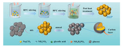
All chemical reagents are of analytical grade without further purification including Na2CO3 (99.8%), NH4VO3 (≥ 99.0%), glycolic acid (≥ 99.0%), NH4H2PO4 (≥ 99.0%) and glucose. Briefly, NVP were prepared via simple sol-gel approach. 7.5 mmol Na2CO3 and 10.0 mmol NH4VO3 were dissolved in 30 mL deionized water and then continuously stirred at 80 ℃ for 30 min. Subsequently, add 10 mmol glycolic acid to the previous solution and continuously stirred about 10 min. Then, 15 mmol NH4H2PO4 was mixed with the solution and kept under stirring at 80 ℃. A gel was form at 80 ℃ after the complete evaporation of the deionized water. Finally, the synthesized precursor was dried overnight in drying oven at 80 ℃. The NVP materials were procured by annealing the NVP precursor at 800 ℃ for 10 h in argon/hydrogen (Ar/H2 = 95/5, v/v) atmosphere at the rate of 2 ℃/min in tube furnace.
Na3V2(PO4)3, coated with different amounts of carbon (NVP/C), were synthesized using a facile approach from the following mass ratios of pure NVP and glucose (95:5, 92.5:7.5, 90:10, 87.5:12.5 and 85:15, w/w). Dissolve the mixture in distilled water and stir continuously for 2 h. The solvent was evaporated by placing the mixture at 80 ℃ in a dust-free oven. Dried materials were crushed into powder. Finally, the samples of NVP/C-5% (95:5, w/w), NVP/C-7.5% (92.5:7.5, w/w), NVP/C-10% (90:10, w/w), NVP/C-12.5% (87.5:12.5, w/w) and NVP/C-15% (85:15, w/w) were obtained via annealing at 650 ℃ for 4 h with Ar/H2 (95%: 5%) atmosphere at a ramping rate of 5 ℃/min.
The X-ray diffraction (XRD, Germany D8 Advance) ranged from 10° to 80° with Cu-Kα radiation (k = 1.54056 Å) is identified to all NVP samples and Raman spectroscopy were performed with Lab Ram HRUV Raman spectrometer having a 532 nm laser source. Scanning electron microscopy (SEM, SU8010) was inspected the morphology and microstructure of all NVP electrode materials. Transmission electron microscopy (TEM) was applied to examine carbon coating thickness via a JEM-2100F operating at 200 kV. The composition of NVP/C-10% powder was determined by EDX (JEOL, JEM-2100F) measurements. Thermo-gravimetric analyzer (TGA, NETZSCH STA 409 PC) was used to obtain the weight fractions of carbon coating layer by heating NVP and NVP/C powders in air with a range of 50~600 ℃ and the ramping rate was 3 ℃/min. And X-ray photoelectron spectroscopy (XPS) system (PHI-QUANTERA-Ⅱ-SXM) was used for determine the valence state of NVP electrode materials surface.
The NVP samples were tested via assembling a standard CR2032 cells in glove box with the Ar-filled and investigated on LAND CT2001A. The as-obtained pure NVP, NVP/C-5%, NVP/C-7.5%, NVP/C-10%, NVP/C-12.5% and NVP/C-15% cathodes consist of 75 wt% of NVP material, 15 wt% of super P and 10 wt% of polyvinylidene fluoride (PVDF). The mass loading of NVP samples were 1~2 mg/cm2. 1 mol/L NaClO4 in EC/PC (EC/PC = 1:1, w/w) with 5% addition of FEC was used as electrolyte. The constant current charge/discharge measurements of all samples were investigated at 2.3–3.9 V for cathode at different current densities.
Cyclic voltammetry (CV) and electrochemical impedance spectroscopy (EIS) measurements (100 kHz to 10 mHz) of CR2032 coin-type cells were tested on CHI 660E electrochemical workstation with the potential range of 2.3–3.9 V. The CR2032 coin-type cells were charged for 30 min in the same voltage window at 0.15 C and then relaxed for 2 h for the galvanostatic intermittent titration technique (GITT) measurement.
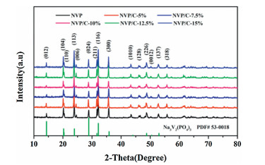
The step-by-step schematic of material synthesis has been shown in Fig. 1. For study the structural evolution of NVP, the XRD diffraction patterns of all NVP materials are displayed in Fig. 2. It is obvious that all diffraction peaks of these powder samples can be matched well with the NASICON structured NVP (JCPDS No. 053-0018) and an R-3c space group (rhombohedral structure). Intensities of the diffraction peaks are strong and sharp, indicating that the synthesized materials possess high degree of crystallinity. Without diffraction peaks of carbon were found in those samples.

|
Download:
|
| Fig. 1. The synthesis process of NVP electrode materials with different carbon content. | |

|
Download:
|
| Fig. 2. (a) XRD patterns of all NVP samples. | |
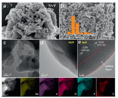
The SEM images reveal the pure NVP structure in Fig. 3a with several agglomerations in comparison to the NVP/C-10% sample in Fig. 3b. The morphology and microstructure of NVP/C-5%, NVP/C-7.5%, NVP/C-12.5% and NVP/C-15% samples are depicted by the SEM images in Fig. S1 (Supporting information). Accordingly, the morphology of NVP/C-10% materials is irregular and the particle size is approximately 617 nm (by surveying 30 NVP nanoparticles using Nano-Measure software, inset Fig. 3b). This method has also been reported [32, 33]. However, the NVP nanoparticles provide a larger specific surface area and contribute to a rapid transfer of sodium ions and electrons in the charge/discharge process. As revealed from the SEM images, only NVP-10% sample comprises of nanoparticles that are uniformly dispersed with no agglomeration of large particles. However, pure NVP and other NVP samples with different carbon content can be observed with some degree of particle agglomeration, which were caused by the inhomogeneous distribution of carbon on the NVP material surface. TEM was further exploited to discuss the morphology of NVP/C-10% sample (c.f. Fig. 3c). Figs. 3d and e present high-resolution TEM (HRTEM) images demonstrate that NVP/C-10% electrode material is well covered by the uniform amorphous carbon layer, which can also be clearly observed on the surface of NVP/C-10% material. And the thickness of the carbon layer is about 13.3 nm (using Nano-Measure software measure). It is noteworthy that carbon-coated layer provides a rapid transmission of electrons and ions throughout the NVP electrode material due to their higher electrical conductivity. The D-spacing of NVP/C-10% materials are about 0.43 nm and 0.37 nm, corresponding to (110) and (113) lattice planes of the NVP (Fig. 3e). EDX mappings demonstrate that all the elements (Na, V, P, O, C) are uniformly scattered in NVP/C-10% materials, which are shown in Fig. 3f.

|
Download:
|
| Fig. 3. Morphological characterizations of NVP and NVP/C-10%. (a, b) SEM images of pure NVP sample and NVP/C-10% sample. (c–e) TEM and HRTEM images of NVP/C-10%. (f) EDX mapping patterns of NVP/C-10%. | |
Raman scattering spectra confirm the presence of carbon in NVP and NVP/C-10% electrode materials (Fig. 4a). The spectrum is divided into three characteristic bands to emphasize the main spectral characteristics. The vibration mode of PO43- ion corresponds to the area of 1000 ~ 1100 cm-1 [34, 35]. Two characteristic bands located around at 1350 cm-1 and 1600 cm−1 can be attributed to D-band (disordered carbon) and G-band (graphitic carbon) of carbon. The ratio ID/IG is indicative of the degree of carbonization [36, 37]. Besides, the peak intensity ratio of D-band and G-band (ID/IG) values of NVP and NVP/C-10% are 0.998 and 0.96, respectively. It indicates that carbon coating layer on NVP/C-10% have high degree of graphitization and a better conductivity [38]. For accurately proving the purity of the coated carbon layer, XPS measurements was performed to reveal the valence states of elements in NVP/C-10% materials (Figs. 4b–f). The survey scan XPS spectrum shows that there are Na 1s, P 2s, P 2p, V 2s, V 2p, O 1s, C 1s and without binding energy peak of other elements (Fig. 4b). The P 2p peak is shown in Fig. 4c with a binding energy of 133.2 eV. The fitted C 1s spectrum (c.f. Fig. 4d) shows four types of carbon located at 284.6, 285.7, 286.6 and 287.8 eV. The peak belongs to the C-C bond used to correct the peaks, and the binding energy is 284.6 eV. The other peaks at higher energies of 285.7, 286.6 and 287.8 eV can be ascribed to the groups of C-O, C=O and O-C=O, respectively [39]. And the V 2p spectra for NVP/C-10% sample appears two peaks located at 516.9 eV and 524.2 eV ascribed to V3+ in NVP [40, 41] along with the Na 1s peak are displayed in Fig. 4f with a binding energy of 1071.2 eV.

|
Download:
|
| Fig. 4. (a) Raman spectroscopies of NVP/C-10%. (b) Survey XPS results of NVP/C-10% sample, (c) P 2p, (d) C 1s, (e) V 2p, (f) Na 1s. | |
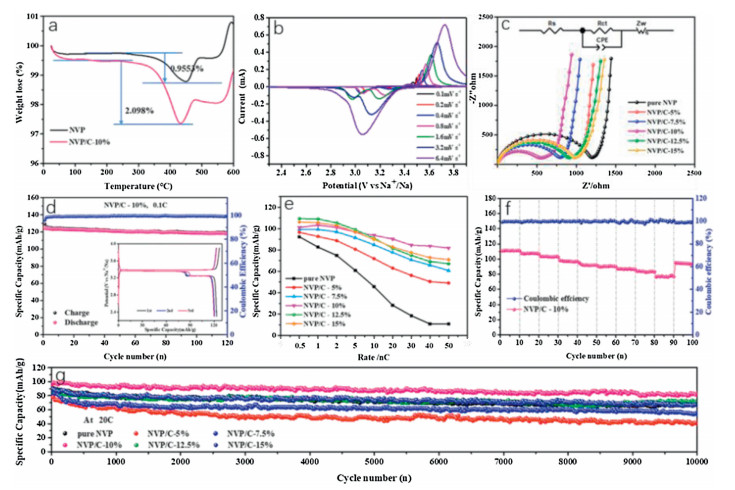
TGA analyses was carried out to investigate the weight fractions of carbon coating layer for pure NVP and NVP/C-10% materials. Fig. 5a displays the TGA results, indicating that the weight fractions of pure NVP and NVP/C-10% materials are 0.9553 wt% and 2.098 wt%, respectively. Na+ diffusion coefficients of NVP/C-10% sample is evaluated at different scanning rates. Fig. 5b displays CV curves of NVP/C-10% sample within 2.3–3.9 V and the redox peaks in curves are related to the redox couple of V3+/V4+. In all those curves, it can be clearly observed that all anodic peaks gradually move to a higher potential with the increases of scan rate, whereas all cathodic peaks move to a lower potential. This phenomenon occurs due to high polarization at high scan rates [42].

|
Download:
|
| Fig. 5. (a) Thermogravimetric curves of pure NVP electrode material and NVP/C-10% material. (b) CV curves under the working voltage of 2.3–3.9 V at different scan rates. (c) Electrochemical impedance spectroscopies of all NVP samples and the inset image show the equivalent circuit. (d) Cycle performance of NVP-10% material at 0.1 C for 120 cycles. (e) Comparison of the different rate capabilities of all NVP samples. (f) Rate performances of NVP/C-10% materials: from 2 C to 200 C. (g) Cycling performance of all NVP samples at 20 C for 10000 cycles. | |
To further investigate the kinetics of those NVP samples, EIS was employed. Fig. 5c shows the Nyquist plots of pure NVP and carbon-coated NVP samples, where each plot is composed of a depressed semicircle part and a straight-line part. And the arc represents charge transfer resistance (Rct). Among those NVP electrodes, the fitted Rct values of NVP/C-10% are apparently smaller indicating greater electrical conductivity. The Na+ diffusion coefficients of all NVP samples are measured by GITT, as displayed in Fig. S2 (Supporting information). The formula for calculation of Na+ diffusion coefficient (DG) is given by
| $ {D_{\rm{G}}} = \frac{4}{{\pi \tau }}{\left( {\frac{{{m_B}{V_m}}}{{{M_B}S}}} \right)^2}{\left( {\frac{{d{E_S}}}{{d{E_\tau }}}} \right)^2} $ | (1) |
Where MB is molecular weight, VM is molar volume, and mB is the mass of NVP samples. τ and S are the time of applying a galvanostatic current and active surface area of the electrode, ΔE and ΔE are the steady-state (equilibrium) potential and change of battery voltage E during the current pulse, respectively. In all samples, the prepared electrode material of NVP/C-10% has the best Na-migration kinetics, in which the DG values are about of 10−12 - 10−11 cm2/s. Notably, calculated DG values of NVP/C-10% are higher than other NVP samples, which further confirm that the carbon-coated layer on NASICON-type NVP effectively facilitates Na+ transport kinetics.
The electrochemical behavior of all NVP samples as cathodes in the half-cell system was studied for SIBs under the working voltage of 2.3–3.9 V. It should be noted that the initial charge/discharge curves of the sample, i.e., NVP/C-10%, was obtained at 0.1 C (Fig. 5d). As observed, two discharge voltage plateaus are located at 3.3 V and 3.4 V respectively. The 3.3 V plateau may be related to the sodium metal surface, which has also been observed before [29, 43]. NVP/C-10% sample shows an eminent discharge capacity of 124.1 mAh/g during the first cycle, which exceeds the theoretical capacity of NVP. After 120 cycles, the reversible capacity of NVP/C-10% is found to be 117.9 mAh/g with the capacity retention rate about 95%, demonstrating that NVP/C-10% has a highly reversible insertion/extraction of Na+. It is worth mentioning that the coulombic efficiency (CE) of NVP/C-10% material in SIBs can almost reach 99.6% during the whole cycling process. Such outstanding electrochemical performances of this composite cathode is because of the apt and uniform carbon layer on NVP surface which accelerates the electrochemical kinetics in SIBs.
The rate performance of all NVP samples were compared in Fig. 5e and Fig. S3 (Supporting information). Among all the samples, NVP/C-10% exhibits excellent rate performance at charge-discharge rates of 0.5, 1, 2, 5, 10, 20 and 50 C, respectively. The capacity retention of NVP/C-10% at different C-rates is higher than other NVP samples. To further investigate NVP/C-10% sample at a higher rate, the electrochemical performance of NVP/C-10% was tested from 2 C to 200 C as shown in Fig. 5f. The reversible capacities obtained for NVP/C-10% were 111.2, 107.8, 103.7, 97.2, 95, 93.3, 91.3, 85.8 and 78.5 mAh/g at 2 C, 5 C, 10 C, 20 C, 30 C, 40 C, 50 C, 100 C and 200 C, respectively. Noticeably, NVP/C-10% sample with the best rate performance was capable of delivering a promising reversible capacity of 78.5 mAh/g even at 200 C. So as to prove the excellent cycle stability of NVP/C-10%, a long cycle measurement was carried out at 20 C (Fig. 5g). Impressively, NVP/C-10% delivered an outstanding discharge capacity of 80.7 mAh/g even after 10000 cycles at 20 C, corresponding to a capacity retention about 83.9% with only 0.155% capacity loss per cycle. However, pure NVP, NVP/C-5%, NVP/C-7.5%, NVP/C-12.5% and NVP/C-15% samples deliver a lower discharge capacity of 68.3, 41, 56.3, 71.4 and 67.6 mAh/g after 10000 cycles, respectively. Moreover, the CE of the NVP/C-10% nearly reached 100%, demonstrating high electrical conductivity and super-reversible insertion/extraction of sodium-ion during electrochemical reaction process. The excellent cycling performance of NVP-10% can also be attributed to the uniform and suitable coating of carbon on NVP electrode material surface, leading to high diffusion kinetics in NVP material with faster electronic and ionic transport.
According to above results, the prepared NVP/C-10% sample showed considerably excellent sodium storage performance. Compared to the previously reported NVP/C composite materials, especially NVP/C composite materials using conventional sources, the NVP/C-10% in this paper has a competitive advantage in mass production (Table S1 in Supporting information). Thus, the facile synthesis strategy of NVP/C proved to be a feasible method for practical applications.
In conclusion, we have testified that sodium storage performance of NVP electrodes can be improved through apposite surface engineering (coated with the suitable carbon layer on NVP electrode material surface). Carbon layers of different thickness have different electrochemical effects on NVP electrode materials. The obtained NVP/C-10% showed a brilliant rate capability (78.5 mAh/g at a rate of 200 C as SIB electrode material) and long cycling life (80.7 mAh/g at 20 C after 10000 cycles). The remarkable cycle performance and rate performance of NVP/C-10% materials can be attributed to the appropriate carbon layer on NVP material surface, improved electronic conductivity and alleviated volume changes. Therefore, a carbon layer with a uniform and suitable thickness on NVP electrode materials makes it a potential candidate with an outstanding cycle lifespan and excellent rate performance.
Declaration of competing interestThe authors declare that they have no known competing financial interests or personal relationships that could have appeared to influence the work reported in this paper.
AcknowledgmentsWe thank the financial supports from the National Natural Science Foundation of China (No. 51774251), Shanghai Science and Technology Commission's "2020 Science and Technology Innovation Action Plan" (No. 20511104003), Hebei Natural Science Foundation for Distinguished Young Scholars (No. B2017203313), Hundred Excellent Innovative Talents Support Program in Hebei Province (No. SLRC2017057), Talent Engineering Training Funds of Hebei Province (No. A201802001), and the Opening Project of the State Key Laboratory of Advanced Chemical Power Sources (No. SKL-ACPS-C-11).
Appendix A. Supplementary dataSupplementary material related to this article can be found, in the online version, at doi:https://doi.org/10.1016/j.cclet.2021.03.005.
| [1] |
F. Li, J. He, J. Liu, et al., Angew. Int. Ed. 60 (2020) 6600-6608. DOI:10.1002/anie.202013993 |
| [2] |
X. Li, S.H. Qi, W.C. Zhang, et al., Rare Metal. 39 (2020) 1239-1255. DOI:10.1007/s12598-020-01492-4 |
| [3] |
J. Ma, Y. Li, N. Grundish, et al., J. Phys. D: Appl. Phys. 54 (2021) 183001. DOI:10.1088/1361-6463/abd353 |
| [4] |
B.H. Hou, Y.Y. Wang, J.Z. Guo, et al., ACS Appl. Mater. Inter. 10 (2018) 3581-3589. DOI:10.1021/acsami.7b16580 |
| [5] |
Y. Zhou, X. Zhang, Y. Liu, et al., Small 16 (2020) 1906669. DOI:10.1002/smll.201906669 |
| [6] |
Z. Zhou, Y. Li, T. Fang, et al., Nanomaterial 9 (2019) 1574. DOI:10.3390/nano9111574 |
| [7] |
G. Harper, R. Sommerville, E. Kendrick, et al., Nature 575 (2019) 75-86. DOI:10.1038/s41586-019-1682-5 |
| [8] |
A. Manthiram, Nat. Commun. 11 (2020) 1550. DOI:10.1038/s41467-020-15355-0 |
| [9] |
F. Wu, J. Maier, Y. Yu, Chem. Soc. Rev. 49 (2020) 1569-1614. DOI:10.1039/C7CS00863E |
| [10] |
P. Yu, W. Tang, F.F. Wu, et al., Rare Metal. 39 (2020) 1019-1033. DOI:10.1007/s12598-020-01443-z |
| [11] |
L. Shen, S. Shi, S. Roy, et al., Adv. Funct. Mater. 31 (2020) 2006066. |
| [12] |
Z. Jian, W. Han, X. Lu, et al., Adv. Energy Mater. 3 (2013) 156-160. DOI:10.1002/aenm.201200558 |
| [13] |
Q. Liu, Z. Hu, M. Chen, et al., Small 15 (2019) 1805381. DOI:10.1002/smll.201805381 |
| [14] |
S. Guo, Q. Li, P. Liu, et al., Nat. Commun. 8 (2017) 135. DOI:10.1038/s41467-017-00157-8 |
| [15] |
I. Hasa, D. Buchholz, S. Passerini, et al., ACS Appl. Mater. Inter. 7 (2015) 5206-5212. DOI:10.1021/am5080437 |
| [16] |
B. Silvan, E. Gonzalo, L. Djuandhi, et al., J. Mater. Chem. A 6 (2018) 15132-15146. DOI:10.1039/C8TA02473A |
| [17] |
Y. Yang, W.F. Wei, Rare Metal. 39 (2020) 332-334. DOI:10.1007/s12598-020-01403-7 |
| [18] |
J.Z. Guo, Y. Yang, D.S. Liu, et al., Adv. Energy Mater. 8 (2018) 1702504. DOI:10.1002/aenm.201702504 |
| [19] |
X.X. Zhao, Z.Y. Gu, W.H. Li, et al., Chem. Eur. J. 26 (2020) 7823-7830. DOI:10.1002/chem.202000943 |
| [20] |
M.Y. Wang, J.Z. Guo, Z.W. Wang, et al., Small 16 (2020) 1907645. DOI:10.1002/smll.201907645 |
| [21] |
J. Kang, S. Baek, V. Mathew, et al., J. Mater. Chem. 22 (2012) 20857-20860. DOI:10.1039/c2jm34451c |
| [22] |
W.X. Song, H.S. Hou, X.B. Ji, Acta Phys. Chim. Sin. 33 (2017) 103-129. DOI:10.3866/PKU.WHXB201608303 |
| [23] |
Y. Fang, L. Xiao, X. Ai, et al., Adv. Mater. 27 (2015) 5895-5900. DOI:10.1002/adma.201502018 |
| [24] |
Y. Jiang, Z. Yang, W. Li, et al., Adv. Energy Mater. 5 (2015) 1402104. DOI:10.1002/aenm.201402104 |
| [25] |
X. Rui, W. Sun, C. Wu, et al., Adv. Mater. 27 (2015) 6670-6676. DOI:10.1002/adma.201502864 |
| [26] |
Z. Jian, L. Zhao, H. Pan, et al., Electrochem. Commun. 14 (2012) 86-89. DOI:10.1016/j.elecom.2011.11.009 |
| [27] |
L.S. Plashnitsa, E. Kobayashi, Y. Noguchi, et al., J. Electrochem. Soc. 157 (2010) A536-A543. DOI:10.1149/1.3298903 |
| [28] |
M.K. Sadan, H. Kim, C. Kim, et al., J. Mater. Chem. A. 8 (2020) 9843-9849. DOI:10.1039/D0TA02721A |
| [29] |
H. Xiong, G. Sun, Z. Liu, et al., Angew. Chem. Int. Ed. 60 (2021) 10334-10341. DOI:10.1002/anie.202100954 |
| [30] |
W. Duan, Z. Zhu, H. Li, et al., J. Mater. Chem. A 2 (2014) 8668-8675. DOI:10.1039/C4TA00106K |
| [31] |
X. Cao, A. Pan, B. Yin, et al., Nano Energy 60 (2019) 312-323. DOI:10.1016/j.nanoen.2019.03.066 |
| [32] |
C.D. Zhao, J.Z. Guo, Z.Y. Gu, et al., J. Mater. Chem. A 8 (2020) 17454-17462. DOI:10.1039/D0TA06614A |
| [33] |
Z.Y. Gu, J.Z. Guo, Z.H. Sun, et al., Sci. Bull. 65 (2020) 702-710. DOI:10.1016/j.scib.2020.01.018 |
| [34] |
W. Li, Z. Yao, Y. Zhong, et al., J. Mater. Chem. A 7 (2019) 10231-10238. DOI:10.1039/C9TA02041A |
| [35] |
C.M. Burba, R. Frech, J. Electrochem. Soc. 151 (2004) A1032-A1038. DOI:10.1149/1.1756885 |
| [36] |
L. Si, Z. Yuan, L. Hu, et al., J. Power Sources 272 (2014) 880-885. DOI:10.1016/j.jpowsour.2014.09.046 |
| [37] |
J. Schwan, S. Ulrich, V. Batori, et al., J. Appl. Phys. 80 (1996) 440-447. DOI:10.1063/1.362745 |
| [38] |
J.D. Wilcox, M.M. Doeff, M. Marcinek, et al., J. Electrochem. Soc. 154 (2007) A389-A395. DOI:10.1149/1.2667591 |
| [39] |
W. Shen, C. Wang, Q. Xu, et al., Adv. Energy Mater. 5 (2015) 1400982. DOI:10.1002/aenm.201400982 |
| [40] |
D. Guo, J. Qin, Z. Yin, et al., Nano Energy. 45 (2018) 136-147. DOI:10.1016/j.nanoen.2017.12.038 |
| [41] |
Q. An, F. Xiong, Q. Wei, et al., Adv. Energy Mater. 5 (2015) 1401963. DOI:10.1002/aenm.201401963 |
| [42] |
Q. Zhu, M. Wang, B. Nan, et al., J. Power Sources 362 (2017) 147-159. DOI:10.1016/j.jpowsour.2017.07.004 |
| [43] |
X. Jiang, T. Zhang, J. Lee, et al., ACS Sustain. Chem. Eng. 5 (2017) 8447-8455. DOI:10.1021/acssuschemeng.7b02355 |