 2021, Vol. 32


b Laboratory of Clean Energy Chemistry and Materials, State Key Laboratory of Solid Lubrication, Lanzhou Institute of Chemical Physics, Chinese Academy of Sciences, Lanzhou 730000, China
With the increasing demand for electric devices, developing a safe and flexible energy storage and conversion system with high energy density has become the focus of attention [1–4]. In recent years, lithium-ion capacitors (LICs) have attracted great attention because they simultaneously inherit the advantage of Lithium-ion batteries (LIBs) with high energy density and the merit of supercapacitors with excellent power characteristic [5,6]. Most of the current research focuses on neutralizing the positive and negative reaction kine ics and improving the energy density of the device via developing dynamics-led battery-type anodes and high-performance capacitive cathodes [7–10]. Even so, the energy density of LICs is much lower than that of LIBs. Very recently, a lithium metal capacitor (LMC) was reported to solve these problems by combining a lithium metal anode and a three-dimensional scaffold activated carbon (3D-SAC) cathode with high surface area and wide pore size distribution in LiPF6/(EC/DEC) electrolyte. In this combination, Li metal anode exhibits extremely high theoretical specific capacitance (3860 mAh/g), low reduction potential (−3.040 V vs. SHE) and improved reaction kinetics between the electrodes [11–13], therefore greatly broadening the voltage window and increasing the capacitance of LMC. Meanwhile, the use of Li metal anode induces the multiple EDLC mechanism of 3D-SAC, which remarkably increases the capacitance and energy density of LMC. Besides, the rapid plating/stripping of Li+ occurring on the surface of the lithium metal anode eliminates the kinetic difference between the anode and cathode of LMC. The appearance of LMC further improves the energy density of LICs, showing great potential in powering electronic devices.
Although LMC exhibits excellent electrochemical performance, the use of liquid electrolytes causes potential safety hazards, hindering the practical application of LMC in electronic devices [14–18]. In LMCs and LIBs, volatile and flammable organic carbonate electrolytes are usually combined with porous polyolefin separators. There is a risk of leakage in abusive environments since the separators cannot fix electrolyte molecules in the matrix [19]. Gel polymer electrolytes (GPEs), owing to their high ionic conductivity and good security, have proven to be the best choice for flexible LIBs, such as a 3D cross-linked network GPE through in situ polymerization MMA and ETPTA monomers on PAN nanofibers [20] and an efficient GPE composed of PVDF-HFP, LiFSI: Pyr13FSI and a Li-MMT clay [21]. The polymer matrix in GPEs immobilizes electrolyte molecules, reducing their reactivity with Li metal and electrolyte consumption [22]. The flexibility of the GPEs exhibits good contact with the electrode and provides energy storage devices with great flexibility and adjustable shapes [23–25]. More importantly, the elasticity of GPE can withstand the volume change of Li anode and inhibit the growth of lithium dendrites [11]. Among numerous GPEs, in situ prepared GPEs have attracted more and more attention due to their high ionic conductivity and simple preparation process [26–30]. Lu et al. crafted a high-performance flexible polymer Li-S battery via an in situ prepared PETEA-based GPE [31]. The Li-S battery exhibited a low electrode/GPE resistance, high rate capacity and improved capacity retention, which are ascribed to the extremely high ionic conductivity, the immobilization of soluble polysulfides and the construction of a robust integrated GPE/electrode interface. The results show that PETEA-based GPE is a promising electrolyte to develop flexible LMC.
Herein, we reported a flexible LMC based on an in situ prepared PETEA-based GPE for the first time. The GPE is composed of pentaerythritol tetraacrylate (PETEA), azodiisobutryronitrile (AIBN) and liquid electrolyte (1 mol/L lithium hexafluorophosphate (LiPF6) salt in a non-aqueous mixture of ethylene carbonate (EC)/diethyl carbonate (DEC) (1:1, v/v)). PETEA-based GPE is formed by the free radical polymerization of PETEA induced by AIBN in the presence of liquid electrolytes. PETEA-based GPE had an extremely high ionic conductivity of 5.75 × 10⁻³ S/cm at room temperature and good contact with electrodes, which endowed the flexible LMC with a high capacitance of 210 F/g at 0.1 A/g within the voltage range from 1.5 V to 4.3 V vs. Li/Li+, a high energy density of 474.4 Wh/kg at 0.1 A/g and a high power density of 29 kW/kg at 10 A/g. The elasticity of GPE is beneficial to tolerate the volume change of Li metal anode and suppress the lithium dendrite growth, thus improving the cycling stability of the LMC. Our results show that the PETEA-based GPE enabled LMC to work normally under abuse tests, such as bending, nail penetration and cutting. The LMC with PETEA-based GPE is expected to be a promising flexible energy storage device for practical application.
A quasi-solid LMC composed of a Li metal anode and a three-dimensional scaffold activated carbon (3D-SAC) cathode was assembled to verify the feasibility of PETEA-based GPE in LMC. Here, the 3D-SAC was chosen due to its large specific surface and wide pore size distribution, which is considered as an excellent capacitive cathode in metal ions capacitor [32]. The as-prepared 3D-SAC showed a typical amorphous characteristic, which could be proved from the XRD pattern (Fig. S1 in Supporting information). The scanning electron microscope (SEM) and transmission electron microscope (TEM) images reflect the three-dimensional porous framework structure of 3D-SAC with a large number of mesopores (Fig. S2 in Supporting information). The nitrogen adsorption/desorption isotherm of 3D-SAC shows its porous structure dominated by micropores (Fig. S3a in Supporting information). The pore size distribution curve shows that the pore size of 3D-SAC is mainly distributed in 1−6 nm (Fig. S3b in Supporting information). A large number of micropores endow 3D-SAC with a high surface area of 2584 m3/g. The high specific surface area and micropore-dominated pore size distribution of 3D-SAC endow the LMC with excellent electrochemical performance.
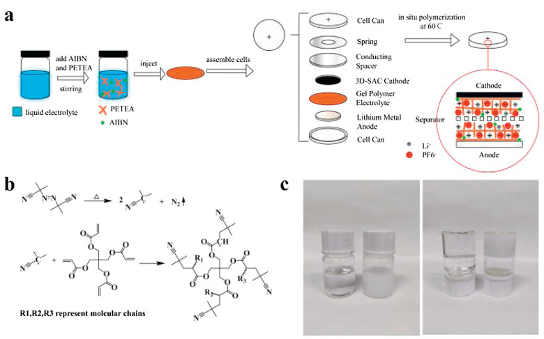
The in situ formation of PETEA-based GPE and the assembly of the quasi-solid LMC are schematically illustrated in Fig. 1a. The fine mixture of azodiisobutyronitrile (AIBN), pentaerythritol tetraacrylate (PETEA) and LiPF6/(EC/DEC) as a precursor solution was heated at 60 ℃. As shown in Fig. 1b, AIBN in the solution decomposed and opened the C = C bonds of PETEA, leading to the continuous growth of polymer chains and the formation of GPE [33]. We chose 3 wt% as the concentration of PETEA because the GPE with 3 wt% PETEA showed both high ionic conductivity and good gelling ability, as shown in Fig. S4 (Supporting information). A coin cell composed of Li metal anode, 3D-SAC cathode and separator injected with the precursor solution was heated to obtain the quasi solid LMC for evaluating the performance of LMC. The optical images of the obtained PETEA-based GPE are shown in Fig. 1c. Compared with the transparent and flowable precursor solution, the GPE became a white solid after heating, indicating the polymerization of PETEA monomers.

|
Download:
|
| Fig. 1. (a) Schematic illustration of the in situ formation of PETEA-based GPE and assembly of the quasi-solid LMC. (b) The formation mechanism of PETEA-based GPE. (c) Optical images of the precursor solution and GPE. | |
We further evaluated the ionic conductivity of PETEA-based GPE via the EIS impedance in a stainless symmetrical coin cell, as shown in Fig. 2a. The ionic conductivity was calculated according to the equation [34]:

|
(1) |

|
Download:
|
| Fig. 2. (a) Impedance plots of a stainless steel symmetrical cell with PETEA-based GPE at the temperature range from 0 ℃ to 80 ℃. (b) The temperature-dependent ionic conductivity curve of PETEA-based GPE. (c) Linear sweep voltammograms of PETEA-based GPE and liquid electrolyte at the scan rate of 1 mV/s. (d) Polarization voltage curves of Li-Li symmetrical cells with liquid electrolyte and PETEA-based GPE at the current density of 1 mA/cm2 with the capacity of 1 mAh/cm2. | |
and the results are shown in Fig. S5 (Supporting information). The temperature-dependent ionic conductivity curve of PETEA-based GPE is shown in Fig. 2b. The results indicated that with the increase of temperature, the internal impedance of PETEA-based GPE decreased, along with the improvement of its ionic conductivity. The PETEA-based GPE exhibited a high ionic conductivity of 3.11 mS/cm at 0 ℃ and 13.46 mS/cm at 80 ℃. It is worth noting that even at 80 ℃, the in situ prepared GPE remained solid without melting, indicating its good thermal stability. To investigate the electrochemical stability of the PETEA-based GPE, we tested the linear sweep voltammograms (LSV) of liquid electrolyte (LiPF6 in EC/DEC) and PETEA-based GPE as shown in Fig. 2c. It shows that the PETEA-based GPE could remain stable even at 4.4 V compared with the 4.25 V decomposition voltage of the liquid electrolyte, indicating that the GPE network inhibit the decomposition of liquid electrolyte. A Li-Li symmetrical cell was assembled to verify the stability of PETEA-based GPE with Li metal anode. It can be seen in Fig. 2d that the Li-Li symmetrical cell with PETEA-based GPE showed a more stable polarization voltage curve compared with liquid electrolyte, indicating its good stability with Li metal anode. With high ionic conductivity, great electrochemical and excellent stability with Li metal anode, the PETEA-based GPE proves to be a promising electrolyte candidate for LMC.
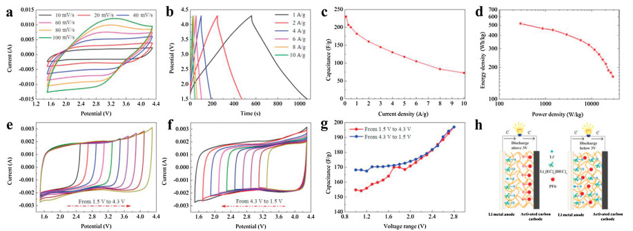
A coin cell was assembled to verify the feasibility of PETEA-based GPE in LMC. As shown in Figs. 3a and b, the assembled LMC exhibited nearly rectangular cyclic voltammetry (CV) curves at different scan rates from 5 mV/s to 100 mV/s and triangular galvanostatic charge-discharge (GCD) curves at different current densities from 1 A/g to 10 A/g, indicating its approximately capacitive energy storage mechanism. The specific capacitances at different current densities were calculated according to the GCD curves, and the results are shown in Fig. 3c. The assembled LMC exhibited a high capacitance of 230 F/g at 0.1 A/g and a capacitance of 72.5 F/g even at 10 A/g, showing its great rate performance. As shown in Fig. S6d (Supporting information), the LMC with GPE showed capacitance comparable with liquid electrolyte at low current densities. However, the capacitance difference of LMCs with two different electrolytes increased with the increase of current densities due to the limited ion transfer in the gel polymer network. The Ragone plots in Fig. 3d show that the assembled LMC exhibited a high energy density of 513 Wh/kg at 0.1 A/g and a high power density of 29 kW/kg at 10 A/g. More importantly, the LMC delivered a high energy density of 265 Wh/kg and a high power density at 14.5 kW/kg at 5 A/g, indicating a great combination of high energy density and high power density.

|
Download:
|
| Fig. 3. (a) CV curves of LMC with PETEA-based GPE at the scan rate from 5 mV/s to 100 mV/s. (b) GCD curves of LMC with PETEA-based GPE at the current density from 1 A/g to 10 A/g. (c) Rate performance of LMC with PETEA-based GPE at various current densities. (d) Ragone plots of LMC with PETEA-based GPE at different current densities. (e) CV curves of LMC with PETEA-based GPE at the voltage range from 1.5 V to 4.3 V with an interval of 0.2 V at the scan rate of 10 mV/s. (f) CV curves of LMC with PETEA-based GPE at the voltage range from 4.3 V to 1.5 V with an interval of 0.1 V at the scan rate of 10 mV/s. (g) Specific capacitances of LMC with PETEA-based GPE in different voltage ranges. (h) The working mechanism of the LMC with PETEA-based GPE during charging. | |
We verified whether the charge storage mechanism of LMC in PETEA-based GPE was the same as that in liquid electrolyte according to the ideal electrical double layer model proposed by Kim et al. [35]. In liquid electrolyte and PETEA-based GPE, there are two charge carriers involving solvated Li+ cation clusters and PF6− anions which may move in the solvents. But different from liquid electrolytes, the solvents in PETEA-based GPE are fixed by the polymer network, which will limit the ions transportation in GPE. As shown in Figs. 3e and f, the assembled LMC exhibited rectangular CV curves in different voltage ranges from 1.5 V to 4.3 V and from 4.3 V to 1.5 V. The specific capacitances calculated from the CV curves are shown in Fig. 3g. The capacitance in the higher voltage area is larger than that in the lower voltage area. As the voltage range increases, the capacitance gap between the opposite charging directions decreases and finally reaches the same value. The voltage dependence of specific capacitance reveals the complex charge storage mechanism of 3D-SAC. The size of Li+[EC]m[DEC]n cation clusters is much larger than PF6−, so it has a lower charge density than PF6− on per unit area, leading to the obvious capacitance hysteresis. This difference in size results in voltage-dependent charge storage behavior. As illustrated in Fig. 3h, in the voltage range of 1.5−3 V, the charge is stored mainly through the adsorption/desorption of Li+[EC]m[DEC]n; in the voltage range of 3–4.3 V, the charge is stored mainly through the adsorption/desorption of PF6−. The results indicate that PF6− can move freely in the GPE, which is necessary for the GPE in LMC.
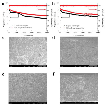
To investigate the electrochemical stability of PETEA-based GPE in the long-term cycle, we tested the cycling performance of the quasi-solid LMC within the voltage range from 1.5 V to 4.3 V at different current densities. Fig. 4a shows the cycling performance of LMC with GPE and liquid electrolyte at 1 A/g. The LMC with PETEA-based GPE delivered an initial capacitance of 160 mAh/g, close to the capacitance of that with liquid electrolyte. After 5000 cycles, the capacitance retention rate of LMC with PETEA-based GPE was 68%, which is far beyond that of liquid electrolyte (54%). The cycling performance of them at 2 A/g is shown in Fig. 4b. LMC with GPE showed a capacity retention of 73% after 5000 cycles, while that of LMC with liquid electrolyte was only 68%. With nearly 100% coulomb efficiency and higher capacitance retention, the in situ prepared PETEA-based GPE shows better cycling stability.

|
Download:
|
| Fig. 4. Cycling performance of LMC with liquid electrolyte and PETEA-based GPE electrolyte at (a) 1 A/g and (b) 2 A/g. (c) Surface SEM images and (d) cross-sectional SEM images of Li metal anode in liquid electrolyte after 3000 cycles at 1 A/g. (e) Surface SEM images and (f) cross-sectional SEM images of Li metal anode in PETEA-based GPE after 3000 cycles at 1 A/g. | |
To explore the reason for the better cycling stability of PETEA-based GPE, we analyzed the morphology of Li metal anode after 3000 cycles at 1 A/g from the surface and cross-section SEM images in Figs. 4c–f. During cycling, the uneven Li+ deposition will induce the continuous growth of Li dendrite, which may puncture the SEI layer and the separator, leading to the short circuit of batteries [36]. After 3000 cycles, the Li metal anode in liquid electrolyte exhibited large dendrites, which passivated Li metal anode and may cause safety hazards. By contrast, the surface of the Li metal anode in GPE was relatively flat and shows a complete structure. The results indicate that the PETEA-based GPE could inhibit the growth of Li dendrite and reduce the safety concerns. After 3000 cycles, the Li metal in liquid electrolyte showed a Li dendrite layer of more than 310 μm, while that of Li anode in PETEA-based GPE was 299 um. Since the Li dendrites near the substrate are easier to strip during cycling, part of the layer away from the substrate will lose its electrochemical activity and become "dead Li", leading to the decay of capacitance. The Li metal in PETEA-based GPE showed a smaller increased thickness, which is responsible for its higher capacitance retention. Besides, the gel polymer network reduces the contact between Li metal and liquid electrolyte and inhibits the growth of Li dendrite, thus reducing the consumption of lithium metal and electrolytes due to SEI rupture/regeneration, which also contributes to the higher capacitance retention rate. The EIS impendence plots of LMC with PETEA-based GPE and liquid electrolyte were shown in Fig. S9 (Supporting information). The contact resistance of LMC with GPE after 1000, 2000, 3000, 4000 cycles were 6.9, 8, 10.2, 12.3 Ω respectively, while that of LMC with liquid electrolyte after 1000, 2000, 3000, 4000 cycles were 7, 12, 18.7, 23.8 Ω respectively. The results show that compared with LMC with liquid electrolyte, the LMC with PETEA-based GPE exlibited a smaller contact resistence after the same number of cycles. It indicates that PETEA-based GPE has an effective inhibition on the "dead Li", which is consistent with the SEM results above.
To verify the application of the PETEA-based GPE in flexible devices, a flexible pouch LMC was assembled as shown in Fig. 5a. As shown in Figs. 5b–d, the flexible LMC showed rectangular CV curves at the scan rates from 5 mV/s to 100 mV/s and approximately triangular GCD curves at the current densities from 0.1 A/g to 10 A/g. It is shown in Fig. 5e that the pouch LMC exhibited a good rate performance with a high specific capacitance of 210 F/g at 0.1 A/g and 85.4 F/g at 10 A/g. As shown in Fig. 5f, the pouch LMC with PETEA-based GPE exhibited a high energy density of 474.4 Wh/kg at 0.1 A/g and a high power density of 29 kW/kg at 10 A/g calculated based on the mass of cathode active materials. After that, the flexibility of the pouch LMC with PETEA-based GPE was verified. As shown in Fig. 5g, under different bending angles of 0°, 45°, 90°, 135° and 180°, the LMC based on PETEA-based GPE showed nearly coincident CV curves, indicating that the LMC could normally work without being affected by shape changes. The safety of the pouch LMC was checked by nail penetration and cutting tests as shown in Fig. 5h. The device could light a LED bulb after nail penetration and cutting in half, indicating its great safety. Also, the pouch LMC could power a small fan after bending, nail penetration and cutting (Video S1 in Supporting information), proving its great safety in practical application.

|
Download:
|
| Fig. 5. (a) Schematic illustration of the soft pouch LMC composing of Li metal anode, gel polymer electrolyte and 3D-SAC cathode. (b) CV curves of the device at different scan rates from 5 mV/s to 100 mV/s. (c, d) GCD curves of the device at the current densities from 0.1 A/g to 10 A/g. (e) Rate performance of the device at different current densities. (f) Ragone plots of the device at different current densities. (g) CV curves of the device at different bending angles of 0°, 45°, 90°, 145° and 180° at 10 mV/s. (h) The device lighting up an LED bulb in abuse tests of nail penetration and cutting in half. | |
In summary, a flexible and safe LMC was reported for the first time. The in situ prepared PETEA-based GPE exhibited a high ionic conductivity of 5.75 × 10⁻³ S/cm at 20 ℃ and good contact with electrodes, endowing the LMC with a high specific capacitance 210 F/g at 0.1 A/g within the voltage range from 1.5 V to 4.3 V vs. Li/Li+, a high energy density of 474 Wh/kg at 0.1 A/g and a high power density of 29 kW/kg at 10 A/g. The elasticity of GPE helped tolerate the volume change of Li metal anode and suppress the lithium dendrite growth, thus improving the cycling stability of LMCs. The PETEA-based GPE enabled the LMC to work normally under abuse tests, such as bending, nail penetration and cutting. Besides, the in situ formation of GPE simplifies the preparation process and facilitates large-scale preparation. The LMC with PETEA-based GPE is expected to be a promising flexible energy storage device for practical application.
Declaration of competing interestThe authors declared that they have no conflicts of interest to this work. Authors declare that they do not have any commercial or associative interest that represents a conflict of interest in connection with the work submitted.
AcknowledgmentsThe authors greatly appreciate the financial support from the Natural Science Foundation of Gansu (No. 20JR10RA611) and the Fundamental Research Funds for the Central Universities (Nos. Lzujbky-2017-178 and lzujbky-2017-181).
Appendix A. Supplementary dataSupplementarymaterial related to this article canbefound, in the online version, at doi:https://doi.org/10.1016/j.cclet.2021.03.069.
| [1] |
S.M. Chen, L.T. Ma, S.L. Wu, et al., Adv. Funct. Mater. 30 (2020) 1908945. DOI:10.1002/adfm.201908945 |
| [2] |
J.J. Zhu, Y.T. Xu, Y.J. Fu, et al., Small 16 (2020) 1905838. DOI:10.1002/smll.201905838 |
| [3] |
J.J. Zhu, Y.L. Li, B.J. Yang, et al., Small 14 (2018) 1801836. DOI:10.1002/smll.201801836 |
| [4] |
X. Long, L. Tian, J. Wang, et al., J. Electroanal. Chem. 877 (2020) 114656. DOI:10.1016/j.jelechem.2020.114656 |
| [5] |
B. Anothumakkool, S. Wiemers-Meyer, D. Guyomard, et al., Adv. Energy Mater. 9 (2019) 1900078. DOI:10.1002/aenm.201900078 |
| [6] |
C.K. Sun, X. Zhang, C. Li, et al., Energy Storage Mater. 32 (2020) 497-516. DOI:10.1016/j.ensm.2020.07.009 |
| [7] |
R.T. Wang, J.W. Lang, P. Zhang, Z.Y. Lin, X.B. Yan, Adv. Funct. Mater. 25 (2015) 2270-2278. DOI:10.1002/adfm.201404472 |
| [8] |
G.C. Li, Z.W. Yang, Z.L. Yin, et al., J. Mater. Chem. A 7 (2019) 15541-15563. DOI:10.1039/C9TA01246J |
| [9] |
Y.G. Sun, J. Tang, F.X. Qin, et al., J. Mater. Chem. A 5 (2017) 13601-13609. DOI:10.1039/C7TA01113J |
| [10] |
B. Li, Z.J. Xiao, M. Chen, et al., J. Mater. Chem A 5 (2017) 24502-24507. DOI:10.1039/C7TA07088H |
| [11] |
Q. Ma, X.X. Zeng, J.P. Yue, et al., Adv. Energy Mater. 9 (2019) 1803854. DOI:10.1002/aenm.201803854 |
| [12] |
W. Xu, J.L. Wang, F. Ding, et al., Energy Environ. Sci. 7 (2014) 513-537. DOI:10.1039/C3EE40795K |
| [13] |
J. Janek, W.G. Zeier, Nat. Energy 1 (2016) 16141. DOI:10.1038/nenergy.2016.141 |
| [14] |
X.L. Cheng, J. Pan, Y. Zhao, M. Liao, H.S. Peng, Adv. Energy Mater. 8 (2018) 1702184. DOI:10.1002/aenm.201702184 |
| [15] |
I. Osada, H. de Vries, B. Scrosati, S. Passerini, Angew. Chem. Int. Ed. 55 (2016) 500-513. DOI:10.1002/anie.201504971 |
| [16] |
M.J. Park, I. Choi, J. Hong, O. Kim, J. Appl. Polym. Sci. 129 (2013) 2363-2376. DOI:10.1002/app.39064 |
| [17] |
J. Kalhoff, G.G. Eshetu, D. Bresser, S. Passerini, ChemSusChem 8 (2015) 2154-2175. DOI:10.1002/cssc.201500284 |
| [18] |
S. Tan, Y.J. Ji, Z.R. Zhang, Y. Yang, ChemPhysChem 15 (2014) 1956-1969. DOI:10.1002/cphc.201402175 |
| [19] |
H. Jia, H. Onishi, R. Wagner, M. Winter, I. Cekic-Laskovic, ACS Appl. Mater. Interfaces 10 (2018) 42348-42355. DOI:10.1021/acsami.8b15505 |
| [20] |
X.L. Zhang, S.Y. Zhao, W. Fan, J.N. Wang, C.J. Li, Electrochim. Acta 301 (2019) 304-311. DOI:10.1016/j.electacta.2019.01.156 |
| [21] |
H. Porthault, C. Calberg, J. Amiran, et al., J. Power Sources 482 (2021) 229055. DOI:10.1016/j.jpowsour.2020.229055 |
| [22] |
M. Armand, Adv. Mater. 2 (1990) 278-286. DOI:10.1002/adma.19900020603 |
| [23] |
W. Weng, Q. Sun, Y. Zhang, et al., Adv. Mater. 27 (2015) 1363-1369. DOI:10.1002/adma.201405127 |
| [24] |
Y.Y. Cui, J.C. Chai, H.P. Du, et al., ACS Appl. Mater. Interfaces 9 (2017) 8737-8741. DOI:10.1021/acsami.6b16218 |
| [25] |
Y. Zhang, Y. Zhao, X.L. Cheng, et al., Angew. Chem. Int. Ed. 54 (2015) 11177-11182. DOI:10.1002/anie.201506142 |
| [26] |
Q.W. Lu, Y.B. He, Q.P. Yu, et al., Adv. Mater. 29 (2017) 1604460. DOI:10.1002/adma.201604460 |
| [27] |
C.Y. Yang, X. Ji, X.L. Fan, et al., Adv. Mater. 29 (2017) 1701972. DOI:10.1002/adma.201701972 |
| [28] |
T. Bok, S.J. Cho, S. Choi, et al., RSC Adv. 6 (2016) 6960-6966. DOI:10.1039/C5RA24256H |
| [29] |
H.S. Kim, S.I. Moon, J. Power Sources 146 (2005) 584-588. DOI:10.1016/j.jpowsour.2005.03.148 |
| [30] |
Y.G. Cho, C. Hwang, D.S. Cheong, Y.S. Kim, H.K. Song, Adv. Mater. 31 (2019) 1804909. DOI:10.1002/adma.201804909 |
| [31] |
M. Liu, D. Zhou, Y.B. He, et al., Nano Energy 22 (2016) 278-289. DOI:10.1016/j.nanoen.2016.02.008 |
| [32] |
B.J. Yang, J.T. Chen, L.Y. Liu, et al., Energy Storage Mater. 23 (2019) 522-529. DOI:10.1016/j.ensm.2019.04.008 |
| [33] |
D. Zhou, L.Z. Fan, H.H. Fan, Q. Shi, Electrochim. Acta 89 (2013) 334-338. DOI:10.1016/j.electacta.2012.11.090 |
| [34] |
R.X. Hu, H.Y. Qiu, H.R. Zhang, et al., Small 16 (2020) 1907163. DOI:10.1002/smll.201907163 |
| [35] |
N.R. Kim, S.M. Lee, M.W. Kim, et al., Adv. Energy Mater. 7 (2017) 1700629. DOI:10.1002/aenm.201700629 |
| [36] |
Y.Y. Liu, D.C. Lin, Y.Z. Li, et al., Nat. Commun. 9 (2018) 3656. DOI:10.1038/s41467-018-06077-5 |