 2021, Vol. 32


Two-dimensional (2D) transition-metal dichalcogenides (TMDCs), an emerging class of materials with stoichiometry MX2 (M = Mo, W; X = S, Se, Te), have attracted considerable attention in recent years. 2D TMDCs possess layer-dependent bandgaps in visible light range [1], strong photoluminescence (PL) [2, 3] and strong excitonic effect [4]. These features endow them excellent optical and electronic properties, and employ them to be the promising building blocks in the next electronic and optoelectronic devices, such as field-effect transistors (FETs) [5, 6], photodetectors [7], solar cells [8] and light-emitting diodes (LEDs) [9]. TMDCs like MoS2 [5], WS2 [10] and WSe2 [6], have been used in FETs as channel materials, while the ability to precisely tune their electronic properties is the key to their successful applications. Doping of 2D TMDCs is one of the important strategies for optimizing and realizing precise control of their electronic performance [11]. Many doping schemes have been performed so far to obtain high charge carrier mobility for fast operation, high on/off ratio for effective switching, and high conductivity and low off-state conductance for low power consumption during operation, which are the most desirable and significant characteristics of high-performance FETs devices [12].
Substitutional doping [13, 14], electrostatic doping [15], and surface charge transfer doping [16, 17] are the most widely utilized approaches to achieve effective n-type or p-type doping in TMDCs. However, these techniques have inevitable shortcomings. Substitutional doping suffers from nonuniformity, a small variation of doping level may lead to large fluctuation of device performance [14, 16]. In addition, it causes damages to lattice structures which lead to severe lattice scattering for charge carriers and degraded carrier mobility [18]. The efficiency of electrostatic doping is not significant and it requires complicated device fabrication processes and complex device architectures [15, 19]. Surface charge transfer doping is of poor stability and controllability because the surface dopants can only be randomly adsorbed on the surface of materials [16]. Therefore, a controllable, nondestructive and reliable strategy is desired to rationally tune the electronic doping of TMDCs. Defects in TMDCs have been demonstrated to have significant influences on their electronic and optical properties [20]. The rational utilization of defects has been proved to be a viable way to facilitate carrier transport and induce effective doping in TMDCs [20]. In principle, anion vacancies as donor sites lead to n-doping, while cation vacancies as acceptor sites lead to p-doping in compound semiconductors [21, 22]. Effective and selective doping can be achieved by introducing a moderate number and specific kinds of defects. Such doping strategies have been developed for WSe2. Mild plasma treatment is employed to selectively create anion vacancies at the metal contact regions, reducing the contact resistance to WSe2 [23]. Ar+ ion-beam irradiation induces surface anion vacancy defects, resulting in ohmic contacts with highly enhanced field effect mobility [24]. However, the strategy of introducing specific and beneficial defects as well as realizing precise control of concentrations and area in 2D materials remains to be explored.
In this work, we realized controllable and effective n-doping in WSe2 monolayers by means of electron beam irradiation. WSe2 is chosen as the representative TMDCs in this study since it is simple to achieve both n-type and p-type transport in WSe2-based devices [6], making WSe2 an excellent candidate for complementary-metal-oxide-semiconductor (CMOS) applications [25]. The n-type doping is empowered by the formation of Se vacancies and it is precisely controlled by the electron-beam fluences. Upon treatments, the source-drain current and the electron mobility of back-gated monolayer WSe2 is enhanced by an order of magnitude and 8 times respectively, which can be attributed to the sharply reduced Schottky barrier width. The quenching of the PL intensity and increase of trion weight further verify the realization of efficient n-type doping. While no obvious changes are found in Raman spectra after irradiation treatment, which indicates the integrity of the lattice structures. The results render this feasible and controllable method great potential of achieving high-performance electronic and optoelectronic devices based on TMDCs.
The WSe2 monolayers were mechanically exfoliated onto silicon substrate with 300 nm SiO2 capping layer using Scotch tape method. The WSe2 devices were fabricated by conventional e-beam lithography technique and lift-off processes. Contacts with 5 nm Ni/50 nm Au were thermally evaporated. The as-made device was wire bonded onto a leaded chip carrier and loaded in the custom-designed vacuum system for electrical measurements. The irradiation process was completed using scanning electron microscope. The accelerating voltage was kept at 10kV, and the spot size was set as 3.5. After drawing the selected region on WSe2 monolayer devices, the dosage can be controlled precisely by changing irradiation dwell time. The Raman and PL mapping were imaged using WITEC (alpha 300R) with excitation of 532 nm laser light and 100 × objective lens with a numerical aperture of 0.9. The Raman and PL spectra were recorded using a LabRAM iHR800 Raman system with excitation of 532 nm laser light and a 50 × objective lens with a numerical aperture of 0.5. Low temperature measurements were performed on an INSTEC HCS421 VXY stage with a mk1000 high-precision temperature controller and LN2-P liquid nitrogen cooling system. Electrical measurements were performed using a Keithley 4200 analyzer at room temperature.
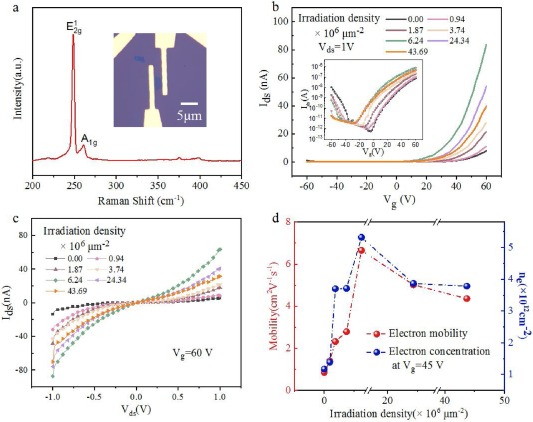
The peak position obtained from PL spectrum (Fig. S1 in Supporting information) and the absence of Raman mode (~310 cm−1) in Raman spectrum (Fig. 1a) identified the monolayer of the flake [26]. To explore the transport behavior of pristine and irradiated WSe2 monolayer, the sample was configured into a back-gated FET device for electrical characterizations. Optical image of FET fabricated from exfoliated WSe2 monolayer is shown in Fig. 1a. Subsequently, the device was subjected to electron beam irradiation with variations intensities of fluence. Fig. 1b displays the transfer characteristics of the as-fabricated WSe2 FET devices with various irradiation density. The measurements were carried out in vacuum (10–1 mbar) under a bias of 1 V at room temperature (300K) using Keithley 4200 semiconductor parameter analyzer. The logarithmic plot of transfer characteristics is presented in the inset. The electron mobility can be extracted from the linear regime of transfer plot via the formula μ = (L/WVdsCi)·(d Ids/d Vg), where L is the channel length, W is the channel width, C is the capacitance per unit area between WSe2 monolayer and back gate given by C = ε0εr/d ≈ 1.15 × 10⁻⁴F/m2 (ε0, εr and d are the vacuum permittivity, the dielectric constant (~3.9) and thickness of SiO2 (300 nm), respectively), Vds = 1 V, and d Ids/d Vg represents the slope of the linear region in transfer characteristic. L and W of this device are 2.20 and 1.67 μm, respectively. The pristine sample shows typical ambipolar transport behavior because the Fermi level in midgap of pristine WSe2 facilitates both electron and hole injections [6]. For pristine WSe2 monolayer, the on-current of pristine device is 0.079 μA (at Vds = 1 V, Vg = 60 V) and the Ids-Vds curves show non-linearity and asymmetry (Fig. 1c and Fig. S2 in Supporting Information), and the electron mobility is calculated to be 0.86 cm2 V−1 s−1. Such poor performances are ascribed to the existence of large Schottky barrier between WSe2 and Ni electrodes. After irradiation treatment with increasing fluences, the on-current is gradually enhanced, and threshold voltage shifts towards left, as shown in the inset of Fig. 1b, indicating n-type doping effect on the irradiated WSe2 FET. The maximal current of 0.83 μA was obtained when the irradiation density was kept at 6.24 × 106μm-2, which is enhanced by an order of magnitude compared to 0.079 μA of the pristine device. However, under higher dosage of irradiation, the current and mobility of the device are reduced due to the introduction of excessive defects. The Ids−Vds output characteristic curves at Vg = 60 V is shown in Fig. 1c. Similarly, the maximum current also exhibits an increase of an order of magnitude. The Ids–Vds curves of pristine and irradiated WSe2 with increasing gate voltages from -60 V to 60 V are shown in Fig. S2 (Supporting Information). Using the equation [27]n = −C(Vg – Vth)/e, the concentration of electron can be extracted from the transfer plot, where e is the electronic charge, and Vth is the threshold voltage that can be obtained by linearly extrapolating transfer curves in the linear regions (Fig. 1b). The calculated electron mobility and concentration (Vg = 45 V) as functions of the irradiation density are plotted in Fig. 1d. The electron mobility significantly improves from 0.86 to 6.66 cm2 V−1 s−1 with irradiation density of 6.24 × 106μm−2. The electron concentration in WSe2 monolayer calculated at Vg = 45 V also increases from 1.17 × 1011cm−2 to 5.32 × 1011cm−2, indicating a considerable injection of electrons. These results confirm the enhancement of n-doping in WSe2 monolayer. However, the mobility and concentration of electron slightly decrease when the dosage continues to increase, due to the introduction of excessive defects. Remarkably, there is no sharp reduction in electrical performance even though the irradiation dosage increases significantly.

|
Download:
|
| Fig. 1. Optical and electrical characterizations of back-gated WSe2 monolayer FET. (a) Raman spectrum and optical microscope image, (b) drain–source current (Ids) versus gate voltage (Vg) transfer characteristics at drain–source voltage Vds = 1 V and (c)Ids–Vds output characteristics at Vg = 60 V of the WSe2 monolayer FET exposed to an increasing dosage of electron beam irradiation. (d) The mobility and concentration of electrons for as-fabricated devices as a function of irradiation density. The accelerating voltage was 10kV. All the measurements were performed under vacuum (~10−1 mbar). | |
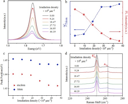
In addition to electrical characterizations, Raman and PL spectra were also performed on the samples at room temperature to demonstrate the n-doping induced by electron beam irradiation. The overall PL intensity gradually decreases when increasing the irradiation dosage (Figs. 2a and b). The fitting results of PL spectra of WSe2 monolayer irradiated with various fluences are shown in Fig. S3 (Supporting information). The PL spectrum was further deconstructed into two peaks, and they are assigned to be trion and neutral exciton peak. As reported previously, the trion in pristine WSe2 is a negatively charged exciton [28]. The trion weight (γ−) is calculated via the formula γ− = Itrion/(Itrion + Iexciton). The PL emission is dimmed, while the trion weight monotonically improves with the increase of irradiation density (Fig. 2b). The irradiation treatment causes electrons injection into the WSe2 monolayer and forms more negative trions, inhibits the formation of neutral excitons and suppresses radiative recombination. For the pristine sample, the positions of exciton and trion peak are located at 1.65 and 1.64 eV, respectively. Both of the peaks displayed ~10 meV redshift after irradiation treatment, and ultimately the overall peak position moved to 1.64 eV and 1.63 eV under high electron beam fluence (Fig. 2c). In contrast to the significant change in PL spectra, no obvious changes are found in Raman spectra after electron beam irradiation (Fig. 2d). It is suggested that the crystal structure of WSe2 monolayer remain comparatively intact after the treatment, implying that the doping technique is relatively mild. To further confirm the homogeneous and mild doping effect of this strategy, PL and Raman mapping were performed on a three-channel WSe2 FET with e-beam irradiation fluence of 0, 9.24, 18.47 × 106μm−2 (Fig. S4 in Supporting information). The PL and Raman intensities of exfoliated WSe2 monolayer exhibit a homogeneous distribution before the devices manufacturing process as shown in mapping results. The PL intensities of the three channels changed after irradiation, among which the high-dose channel decreased most obviously, while the Raman spectrum remained highly homogeneous. Uniform quenching occurred in the irradiated area of the channels as proved by the PL mapping. Atomic force microscope images acquired on pristine WSe2 monolayer and irradiated WSe2 monolayer are shown in Fig. S5 (Supporting information). The thickness and surface roughness of samples exhibit no obvious difference after irradiation. These results further verify this homogeneous and mild doping technique via e-beam irradiation.

|
Download:
|
| Fig. 2. Spectroscopic characterizations of WSe2 monolayer. (a) PL spectra, (b) variations of the trion weight and PL intensity, (c) variations of peak positions of trion and exciton emission and (d) Raman spectra of WSe2 monolayer with increasing irradiation density. | |
Transformations of the atomic structure and surface morphology can be introduced via e-beam irradiation in a controllable manner, as proved by a large number of experimental studies [29-31]. E-beam irradiation with accelerating voltage much lower than the knock-on damage threshold can generate anion vacancy in monolayer TMDCs via ionization damage [29]. To probe the structural defects in TMDCs, PL spectra at 84K were performed on the pristine and irradiated samples. For pristine sample, two prominent peaks are observed at 1.70 eV and 1.74 eV (Fig. 3a), corresponding to the radiative recombination of negatively charged excitons (X−) and neutral excitons (X0) [32, 33]. After electron beam irradiation, a new peak with asymmetric line shape emerges at 1.62 eV (Xb), which is assigned to be defect-bound exciton. The defects induced by e-beam irradiation are mainly Se vacancies, because the ionization energy of Se atoms in WSe2 monolayer is relatively small [28] and the emission of excitons bound to Se vacancies exactly locates at 130 meV lower than the X0 emission [34]. Furthermore, the intensity of Xb monotonously increases with increasing irradiation dosage while intensity of X0 and X− quench, suggesting the possibility of defects-modulated photoluminescence. Further confirmation of the defect origin of the Xb peak is supported by the temperature- and power-dependence of PL spectra collected from irradiated samples (Figs. 3b and c). PL characteristics of irradiated samples (18.47 × 106μm-2) at low temperature are given in Fig. S6 (Supporting information). Xb peak is disappeared at higher temperature as excitons are not tightly bound to defects and the weak interaction is susceptible to thermal perturbations [35, 36]. Furthermore, the intensity of Xb peak tends to saturate at high excitation powers because defect states are fully populated with excitons under relative high laser power at 84K (Fig. 3d) [35-37]. The power dependence of Xb can be described by the formula I [35, 36, 38]. The value of parameter k is calculated to be approximately equal to 0.7, corresponding to recombination of excitons bound to Se vacancy defects [34, 36]. By comparing the values of the saturated PL intensity of Xb, it is determined that the defect density increase as electron beam irradiation dose increases, which renders this technique prospective to accomplish rational design of defect density and doping level in WSe2 monolayer.

|
Download:
|
| Fig. 3. PL characteristics of WSe2 monolayer at low temperature. (a) PL spectra of WSe2 monolayer treated with different irradiation dosage collected at 84K with a laser power of 1.0 μW. (b) PL spectra of WSe2 monolayer treated with specific irradiation dosage (9.24 × 106μm−2) measured at different temperatures. The inset is the intensity of Xb emission as a function of temperature. (c) PL spectra (normalized by the intensity of X0 peak) of WSe2 monolayer treated with specific irradiation dosage (9.24 × 106μm−2) under the excitation with different laser power. (d) The excitation dependence of the integrated intensities of the Xb emission with electron beam densities of 9.24 × 10⁶ and 18.47 × 106μm−2. The solid curves are the fitting results according to the power law I ∝ Pk. | |
The improvement in drain current of WSe2 FET via e-beam irradiation can be interpreted as follows. Before irradiation treatment, the pristine sample shows typical ambipolar transfer behavior resulting from the Fermi level in midgap of pristine WSe2 which facilitates both electron and hole injections [6]. Se vacancies are generated in WSe2 monolayer after irradiation, as shown in Fig. 4a, which causes unsaturated electrons in the surrounding W atoms leading to enhanced electron concentration in channel and higher channel conductance [39, 40] and acts as charge hopping transport sites. Furthermore, the increasing Se vacancies density promotes the probability of charge hopping transport [39, 41]. As a result, more free electrons are involved in charge transport. On the other hand, the n-doping moves the Fermi level from near midgap to closer to the conduction band [42], and results in enhanced "downward" band bending of the conduction band as shown in Fig. 4b. The width of Schottky barrier formed at the interface between source/drain metal and material in the lateral access region is decreased significantly. Compared to the pristine WSe2 FET, it is relatively easier for electrons to be injected into the conduction band due to the enhanced electron tunneling of the thinned Schottky barrier width. The contact resistance is significantly reduced when tunnel current dominates over thermionic current, resulting in enhancement in source-drain current and mobility of electrons. This is in accordance with previous experimental studies on TMDCs-based FETs where doping in the channel/access regions contributes to the reduction of the contact resistance induced by Schottky barrier and thus enhance the electrical performance of FETs [40, 43, 44]. However, with further increase of irradiation dose, more Se vacancies defects are created in WSe2 flake, enhancing the probability of carrier scattering and defects capturing carriers [39]. Therefore, the mobility and concentration of electrons gradually decrease under high electron-beam dosage. This technique possesses potential in rational regulation of the electrical performance of TMDCs-based FETs since the electron beam irradiation treatment is of high resolution compared to other doping methods and the irradiation dosage and pattern of irradiated area could be controlled precisely during EBL process. With precise and appropriate design of the irradiated area in the access region between channel and electrodes, better performance FETs devices are expected to fabricate.

|
Download:
|
| Fig. 4. (a) Schematic of the WSe2 flake after the irradiation treatment, illustrating the creation of Se vacancies. (b) Schematic band alignment diagrams at the Ni/WSe2 junctions for pristine and doped samples. | |
In summary, we have demonstrated that controllable and effective n-type doping can be accomplished in monolayer WSe2 via electron-beam irradiation. This strategy is capable of precise manipulation of defects density and location, and immune from contamination in high vacuum during the treated process in comparison with plasma and chemical treatment. The integrity of lattice structure is kept even under high-dose irradiation as proved by Raman spectrum. The n-type doping arises from the generation of Se vacancies, and the doping area and degree can be precisely controlled with sub-microscale resolution via irradiation treatment. Electrical measurements were performed to confirm the significant improvement in electron mobility and density. Upon irradiation, the current of back-gated monolayer WSe2 FET is enhanced by an order of magnitude, and the field mobility is enhanced by 8 times, which is attributed to the sharply reduced Schottky barrier width. This work provides a promising approach for utilizing defects in TMDCs and achieving high-performance electronic and optoelectronic devices.
Declaration of competing interestThe authors report no declarations of interest.
AcknowledgmentsThis work was supported by the KRDPC (No. 2019YFA0308000) and National Natural Science Foundation of China (Nos. 61927808 and 91963130).
Appendix A. Supplementary dataSupplementary material related to this article can be found, in the online version, at doi:https://doi.org/10.1016/j.cclet.2021.03.048.
| [1] |
W.S. Yun, S.W. Han, S.C. Hong, I.G. Kim, J.D. Lee, Phys. Rev. B 85 (2012) 033305. DOI:10.1103/PhysRevB.85.033305 |
| [2] |
D. Voiry, A. Goswami, R. Kappera, et al., Nat. Chem. 7 (2015) 45-49. DOI:10.1038/nchem.2108 |
| [3] |
X. Hong, J. Kim, S.F. Shi, et al., Nat. Nanotechnol. 9 (2014) 682-686. DOI:10.1038/nnano.2014.167 |
| [4] |
K.F. Mak, J. Shan, Nat. Photonics 10 (2016) 216-226. DOI:10.1038/nphoton.2015.282 |
| [5] |
Y. Zhang, J. Ye, Y. Matsuhashi, Y. Iwasa, Nano Lett. 12 (2012) 1136-1140. DOI:10.1021/nl2021575 |
| [6] |
S. Das, J. Appenzeller, Appl. Phys. Lett. 103 (2013) 103501. DOI:10.1063/1.4820408 |
| [7] |
C. Xie, C. Mak, X. Tao, F. Yan, Adv. Funct. Mater. 27 (2017) 1603886. DOI:10.1002/adfm.201603886 |
| [8] |
M.L. Tsai, S.H. Su, J.K. Chang, et al., ACS Nano 8 (2014) 8317-8322. DOI:10.1021/nn502776h |
| [9] |
J.S. Ross, P. Klement, A.M. Jones, et al., Nat. Nanotechnol. 9 (2014) 268-272. DOI:10.1038/nnano.2014.26 |
| [10] |
D. Ovchinnikov, A. Allain, Y.S. Huang, D. Dumcenco, A. Kis, ACS Nano 8 (2014) 8174-8181. DOI:10.1021/nn502362b |
| [11] |
P. Luo, F. Zhuge, Q. Zhang, et al., Nanoscale Horiz. 4 (2019) 26-51. DOI:10.1039/c8nh00150b |
| [12] |
Q.H. Wang, K. Kalantar-Zadeh, A. Kis, J.N. Coleman, M.S. Strano, Nat. Nanotechnol. 7 (2012) 699-712. DOI:10.1038/nnano.2012.193 |
| [13] |
F. Zhang, Y. Lu, D.S. Schulman, et al., Sci. Adv. 5 (2019) eaav5003. DOI:10.1126/sciadv.aav5003 |
| [14] |
S.K. Pandey, H. Alsalman, J.G. Azadani, et al., Nanoscale 10 (2018) 21374-21385. DOI:10.1039/c8nr07070a |
| [15] |
Y. Wang, J. Xiao, H. Zhu, et al., Nature 550 (2017) 487-491. DOI:10.1038/nature24043 |
| [16] |
X. Zhang, Z. Shao, X. Zhang, Y. He, J. Jie, Adv. Mater. 28 (2016) 10409-10442. DOI:10.1002/adma.201601966 |
| [17] |
C. Zhang, C. Wang, F. Yang, et al., ACS Nano 13 (2019) 1595-1602. DOI:10.1080/21691401.2019.1605371 |
| [18] |
Z. Jin, Y. Yao, C. Kittrell, J.M. Tour, ACS Nano 5 (2011) 4112-4117. DOI:10.1021/nn200766e |
| [19] |
D.H. Lien, S.Z. Uddin, M. Yeh, et al., Science 364 (2019) 468-471. DOI:10.1126/science.aaw8053 |
| [20] |
Z. Hu, Z. Wu, C. Han, et al., Chem. Soc. Rev. 47 (2018) 3100-3128. DOI:10.1039/c8cs00024g |
| [21] |
P. Ebert, Surf. Sci. Rep. 33 (1999) 121-303. DOI:10.1016/S0167-5729(98)00011-9 |
| [22] |
R. Addou, L. Colombo, R.M. Wallace, ACS Appl. Mater. Interfaces 7 (2015) 11921-11929. DOI:10.1021/acsami.5b01778 |
| [23] |
M. Tosun, L. Chan, M. Amani, et al., ACS Nano 10 (2016) 6853-6860. DOI:10.1021/acsnano.6b02521 |
| [24] |
D. Kim, H. Du, T. Kim, et al., AIP Adv. 6 (2016) 105307. DOI:10.1063/1.4966049 |
| [25] |
L. Yu, A. Zubair, E.J. Santos, et al., Nano Lett. 15 (2015) 4928-4934. DOI:10.1021/acs.nanolett.5b00668 |
| [26] |
P. Tonndorf, R. Schmidt, P. Böttger, et al., Opt. Express 21 (2013) 4908-4916. DOI:10.1364/OE.21.004908 |
| [27] |
B. Lei, Z. Hu, D. Xiang, et al., Nano Res. 10 (2017) 1282-1291. DOI:10.1007/s12274-016-1386-1 |
| [28] |
Z. Li, T. Wang, Z. Lu, et al., Nat. Commun. 9 (2018) 3719. DOI:10.1038/s41467-018-05863-5 |
| [29] |
J. Jiang, T. Xu, J. Lu, L. Sun, Z. Ni, Research 2019 (2019) 4641739. |
| [30] |
H.P. Komsa, J. Kotakoski, S. Kurasch, et al., Phys. Rev. Lett. 109 (2012) 035503. DOI:10.1103/PhysRevLett.109.035503 |
| [31] |
H.P. Komsa, S. Kurasch, O. Lehtinen, U. Kaiser, A.V. Krasheninnikov, Phys. Rev. B 88 (2013) 035301. DOI:10.1103/PhysRevB.88.035301 |
| [32] |
J. Huang, T.B. Hoang, M.H. Mikkelsen, Sci. Rep. 6 (2016) 22414. DOI:10.1038/srep22414 |
| [33] |
E. Courtade, M. Semina, M. Manca, et al., Phys. Rev. B 96 (2017) 085302. DOI:10.1103/PhysRevB.96.085302 |
| [34] |
G. Moody, K. Tran, X. Lu, et al., Phys. Rev. Lett. 121 (2018) 057403. DOI:10.1103/PhysRevLett.121.057403 |
| [35] |
S. Tongay, J. Suh, C. Ataca, et al., Sci. Rep. 3 (2013) 2657. DOI:10.1038/srep02657 |
| [36] |
Z. Wu, W. Zhao, J. Jiang, et al., J. Phys. Chem. C 121 (2017) 12294-12299. DOI:10.1021/acs.jpcc.7b03585 |
| [37] |
P.K. Chow, R.B. Jacobs-Gedrim, J. Gao, et al., ACS Nano 9 (2015) 1520-1527. DOI:10.1021/nn5073495 |
| [38] |
T. Schmidt, K. Lischka, W. Zulehner, Phys. Rev., B Condens. Matter 45 (1992) 8989-8994. DOI:10.1103/PhysRevB.45.8989 |
| [39] |
H. Qiu, T. Xu, Z. Wang, et al., Nat. Commun. 4 (2013) 2642. DOI:10.1038/ncomms3642 |
| [40] |
H.M. Khalil, M.F. Khan, J. Eom, H. Noh, ACS Appl. Mater. Interfaces 7 (2015) 23589-23596. DOI:10.1021/acsami.5b06825 |
| [41] |
X. Zhang, Q. Liao, Z. Kang, et al., Adv. Mater. 33 (2021) e2007051. DOI:10.1002/adma.202007051 |
| [42] |
Z. Cui, X. Ke, E. Li, et al., Opt. Quantum Electronics 50 (2017) 1. DOI:10.1145/3072959.3073612 |
| [43] |
J.H. Park, A. Rai, J. Hwang, et al., ACS Nano 13 (2019) 7545-7555. DOI:10.1021/acsnano.8b09351 |
| [44] |
X. Zheng, X. Zhang, Y. Wei, et al., Nano Res. 13 (2020) 952-958. DOI:10.1007/s12274-020-2724-x |